

vanilla allpass / nested allpass filter
@Ice-Ice Well, I was hoping that if I followed that same tutorial I might be able to remedy some of my ignorance of low-level filter construction.
Nope! ")
But maybe what I made is still useful to you. This is untested because I honestly don't understand what I should be testing for. The examples on that tutorial sound more like feedback delays than all pass filters to me, but that just may be more of my ignorance. That said, my gut tells me that you can't just mashup H14 and this filter diagram--they're slightly different instances of the same thing.
allpass~.pd
Edit: Oooh, I think I see what's going on!
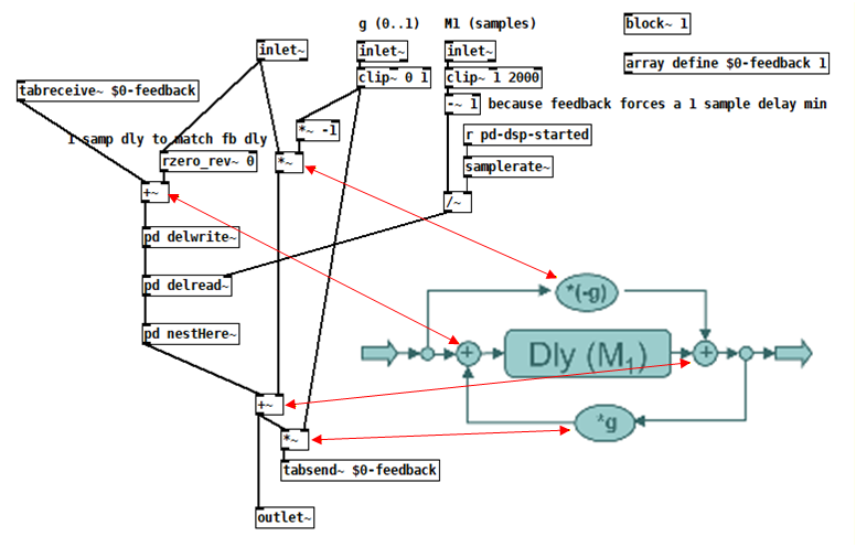
H14 implements the APF using [rzero-rev~] fed into [rpole~]. From help:
    [rzero-rev~] implements y[n] = -a * x[n] + x[n-1]
    [rpole~] implements y[n] = x[n] + a * y[n-1]
Since the first equation provides input to the second, substitute x[n] in the second with the output equation of the first:
y[n] = -a * x[n] + x[n-1] + a * y[n-1]
Now make an equation for that tutorial's diagram:
y[n] = -g * x[n] + x[n-M1] + g * y[n-M1]
The first term represents the upper path, the second term is the middle path through the delay, and the last term is the feedback going through the same delay!
So H14 is the same only if a = g and M1 = 1.
 posted in technical issues
snapshotting and restoring the state of a [phasor~] exactly
@FFW @jameslo @FFW @jameslo @FFW @jameslo
a quick attempt,
updated 100 times
now with one repeating sequence, 2 seconds , 50 phasors in parallel, I am done now, good night
 posted in technical issues
[vline~] may not start at block boundaries
@whale-av said:
@jameslo Pretty sure it is documented here...
Messages are received and run out during an audio block?...... but the resulting instructions are not passed to an object until the next boundary?..... at which time they will be scheduled to be acted upon within the next block if the object can do so?.
Yep, I think that's it, so let me list some of the ways I don't understand things
[1] Not reading the documentation
[2] Not understanding the documentation I've read
[3] Forgetting what I used to understand
In the middle of a message cascade you may schedule another one at a delay of zero. This delayed cascade happens after the present cascade has finished, but at the same logical time".
Man, this got me excited because the only reason my bang quantizer outputs where it does and not one block earlier is because [bang~] for the end of the first block has already executed by the time my spigot opens and so we have to wait for the next audio block to complete. I was hoping [delay 0] would cause the bang from [bang~] to be rescheduled after my spigot opens, but it doesn't appear to.
posted in technical issues
Pd compiled for double-precision floats and Windows
@ddw_music I love that story but am scratching my head over the 1/10 example you gave. Here's a test I made in Arduino c++:
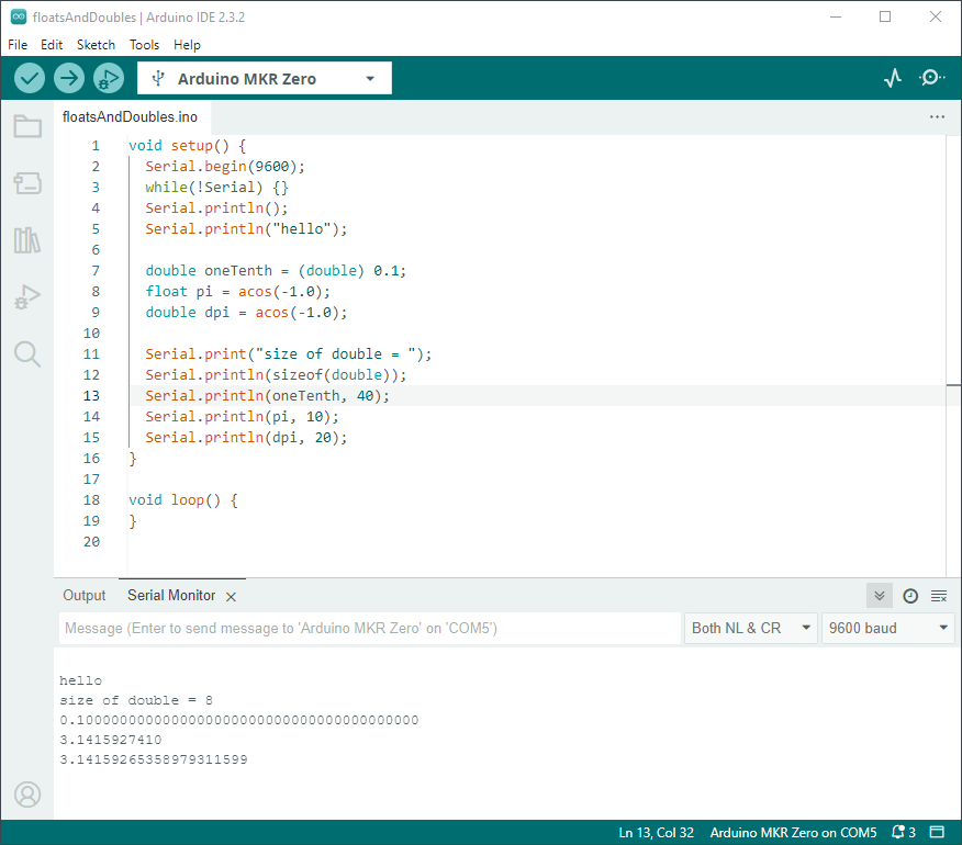
I went out 40 digits and didn't see anything unexpected. Was that example you gave just a metaphor for the issue, or is my test naive?
Getting back to how Pd seems to differ from other programming languages, I'm going to hazard a guess and say that Pd hasn't separated the value of a float from its display/storage format. In my Arduino code I declare values, but it's not until the print statements that I specify their display formats. It's similar in Java and c#. I wonder if Pd could do something similar without upsetting users or making it too unfriendly? Maybe number boxes and arrays have an extra property that is a numeric format string? Or set messages for messages end in a numeric format string? Format strings shouldn't be too unfamiliar to those who've used makefilename. And if the format string is missing, then Pd defaults to it's current single-precision truncation strategy?
PS I hope my attempt at humor didn't discourage @porres from responding to @oid's question. I'm sure he would have something more meaningful to contribute.
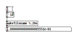
Edit: hmm, but here's Pd64.
Yet another edit: I found this in Microsoft Excel help, but it suggests the value should be slightly less, not more that 0.1. Plus, Excel shows 0.1 exactly.
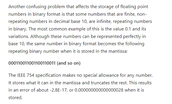
Yet another edit edit: disregard my comment about expecting it to be less, I didn't account for normalization of the mantissa. Carry on.
posted in technical issues
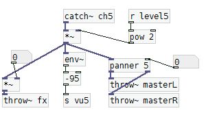
I have a problem with a mixer.
@Carambolooo You have forgotten to connect the right inlets of the [*~] volume controls for the effects channels.
Here is an abstraction that will give you the [panner] objects........ panner.pd
Put it in the same folder as your patch, then re-open your patch and for each instance give it an argument.
...... so in your patch change each [panner] to [panner 1] [panner 2] etc.....
That will keep them separate..... each one will receive control messages from only the fader that you wish.
Look inside [panner]. You will see at the top [r pan$1]. The $1 will take the argument you have just added to each [panner] as it is created.
Before you continue you should get to grips with abstractions...... that will save you a lot of time as you develop your patches......... https://forum.pdpatchrepo.info/topic/9774/pure-data-noob
You need to change all the hsliders controlling the pan to have a range of 0 to 1
In fact all your sliders need to have a range of 0 to 1 (because audio values in Pd must be in that range) and you will have to change them all in their properties pop up window..
You might well need to reduce the volume after your [catch~] objects as well because adding lots of [throw~] sends together will give you a final output greater than 1.
As @benalb says...... we have no "multiply defined" problems in Pd.
My best guess is that you have opened your patch twice..... effectively having each [catch~] then created twice in the plugdata program.
David.
Ps.... other parts of your patch could also be abstractions...... e.g.
You would create an abstraction...... say [mymix] and give that the argument for the channel number..... [mymix 5] etc.
Inside it would look like this......
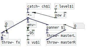
..... and [panner $1] would then get the same argument (5 in this case) from its parent abstraction.... its a sort of magic...... 
And adding a $0 to all the send and receive names would mean that you can open your [mixer] twice without cross communication and without any "multiply defined" errors.
You could even include the control faders and VU's and show them through the GOP window of the abstraction...... another subject, but see the link above.......
Expanding your patch would then be child's play rather than a lengthy process prone to errors.
It's a lot to learn in one hit..... but well worth the effort...
 posted in technical issues
help with polyphonic synth
I realized, after posting that, that there are two ways of thinking about the "extra parameters" going into the synth clone, which for lack of a better term I could call "global" vs "local" parameters.
Local parameters are "per-note" -- they are set at the time the note begins, and they hold their value for the duration of the note. The next note (which might overlap) could have completely different values.
Global parameters affect all notes simultaneously. This is the usual way that, for instance, filter frequency works. You twist the filter cutoff knob and all notes' cutoff changes simultaneously (even though each note could have its own filter cutoff envelope).
At minimum, pitch (note number or frequency) and velocity (on/off trigger) should be per-note. Other parameters could be global or local (and you can mix those styles).
As far as I can see, the best way is:
- All local parameters get packed into a list, along with the clone instance number (which is supplied by [poly]). The "local" list goes into the leftmost input, and only the leftmost.
- "Global" parameters add one or more inlets to the right. Note carefully in the [clone] help file that control inlets need to tag their values for specific instances. If we're using these as global parameters, then the tag should be
all. Signal inlets are always global.
IMO it's best to be consistent about the handling of these input types, to avoid introducing bugs into your patch.
Example with filter cutoff and envelope parameters treated globally:
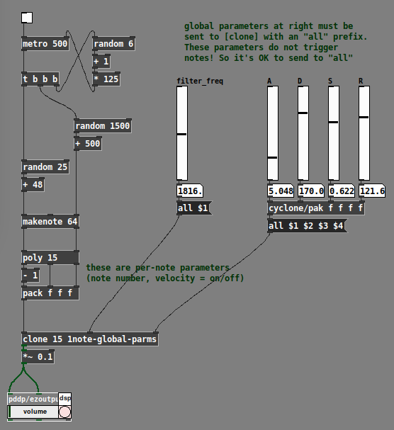
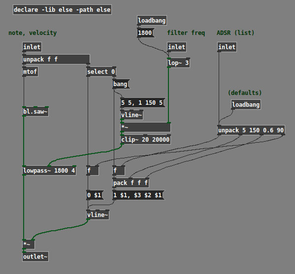
Example with filter cutoff and envelope parameters treated locally:
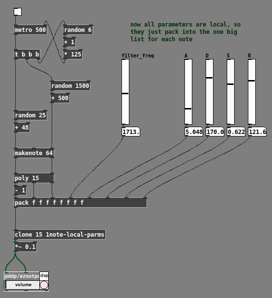
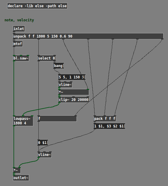
(Note: The example patches use the ELSE external library, and the global one uses cyclone.)
Hope this helps. IMO polysynth is a basic use case for any audio programming environment; if what I've posted here can't be easily figured out from the documentation, then it suggests a gap in the help. (One reason why I worked it out is that I teach a class in Pd; if the students ask "how do I make a poly synth?" then I'd better have an answer at the ready. So I tried a few ways and came up with this as a basic template that Just Works... then, just do it that way.)
hjh
 posted in technical issues
Trying to understand how to compile PD Externals (static library and Windows)
@lo94 one issue is the multiple coexisting uses of the term 'library'.. in pd terms 'library' is usually a set of distributed classes, whether those are abstractions or compiled objects.
however, compiled objects can come either in a single binary (usually with the name of the library) or multiple binaries.
If they come in a single binary (like zexy these days), then you can load the classes in that binary with the 'library' startup option or [declare] it.
But if the classes come as separate binaries or abstractions you can just use the class's name to load the class & create an object if it is in the path. (and if not you can add the path with the path startup option or [declare] it as well)
If you try to create an object with a certain name pd will look for it to see if it's already loaded, then it will look for binaries with that name and call a corresponding setup function in the binary if it finds one. So if the setup function has _tilde then the binary it's in must also have a tilde and the object must be created with one too (if the classes are distributed in separate binaries).
However in single-binary libraries you can register alternate ways to create objects of a certain class when the library loads. (zexy uses this for instance, you can use either [demux] or [demultiplex] to create an object of the demultiplex class)
 posted in technical issues
Convert analog reading of a microphone back into sound
hey @whale-av @manuels @jameslo thanks once again for the feedback! I think we are getting there, very exciting. I just quickly plugged your suggestion into my patches and they both work well. Interestingly enough now the sig~ and the resampling method result in two sounds that are timbrically quite different, but still coherent with what I would expect. This is super interesting, even as a creative toolset, as long as the difference in timbre are not artefacts. I will investigate this further and try to post some audio examples.
Gonna work more on the project this week and keep you posted. Just bear with me as I cannot work on this full-on every day like the past weekend, cause of other commitments.
@jameslo sorry to hear, it is quite jumping around these days, I hope your symptoms are bearable, and I'm glad that an interesting problem can help a little
@whale-av the vline~ there is very elegant! I had previously tried with a line3 in the control domain but your suggestions makes more sense. I've used a bucket object to get the interval, that should be the same as what you are doing in your patch.
@manuels yes, indeed. Different filters are the next thing I'm gonna look into, especially as I gonna need a more systematic spectral analysis of the resulting sound to make sure it is still coherent with the expected signal.
 posted in technical issues
Convert analog reading of a microphone back into sound
@MarcoDonnarumma The jitter seems unpredictable in your data.... so...
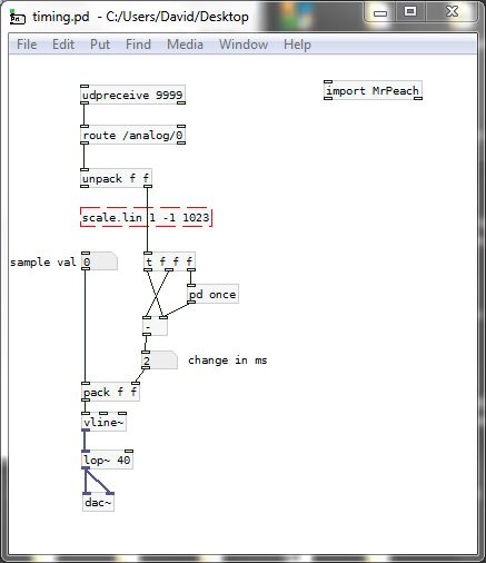
Trying to put the samples at the correct time...... and keep the patch simple with as little delay as possible..... (If only because I don't have the expertise of @jameslo and @manuels).
I am much more comfortable at control rate....... 
The timings from the arduino are not really accurate enough but they will help to massively decrease the jitter.
The [lop~] value can probably be increased as [vline~] will create ramps between samples rather than steps.
If you can send more accurate timings it will improve without changes to the patch...... i.e 231.445.
But beware that as the ms timing values get bigger all the time they will become less accurate in the osc and probably hit the Pd limit for representation........ sorry I didn't think of that before.
So it would be better to send the time difference between samples so that the values stay within range...... with the added bonus that my patch would then only contain 8 objects including [udpreceive] and the [dac~]...... 
I cannot connect it properly as I don't have [scale.lin] but here it is......
timing.pd
Please don't laugh.
David.
P.S. If the results are worse than your previous test with [lop~] it is because the arrival of the osc messages is better timed than the sample time stamps that the arduino is sending.
posted in technical issues