how to limit DS array value range
@ingox @Jona @whale-av @Balwyn People, you are really amazing! ") All these hints are very useful! in this particular case, @ingox / @whale-av 's tip regarding [receive pd] is a solution, which works pretty well and makes [mousestate] unnecessary! however, a big thanks to each of you!
All these hints are very useful! in this particular case, @ingox / @whale-av 's tip regarding [receive pd] is a solution, which works pretty well and makes [mousestate] unnecessary! however, a big thanks to each of you!
 posted in technical issues
data structures - xy-pad in value range 0-1
oh, great - thanks for all the replies!
@ingox
Is it possible that you are using @Balwyn's xy-patch
no, not this patch, but yeah, i was inspired by another patch i found here somewhere in the forum... don't remembr exactly which one, but this got me started - i'm still trying to get into data structures, which is quite hard sometimes, so it's really good to have some patches to get started with...
It is that data structures get an invisible dragging area of 10 or 12 pixels squared. This is not documented and i don't remember the exact circumstances how the area is created. But the dragging area is unfortunately independent from the displayed form in size, so a bigger form can not be dragged at any point. Hope that helps a little bit.
yeah, i was afraid, this could be the answer! ")
@Balwyn said:
@toxonic just multiplying the outputs by 0.01 gives the same result
yes, correct - it's not a big deal to convert the output into any range, but i just hoped to keep things simple....
@Balwyn said:
@toxonic You may get some insight into using the hotspot without a pointer with this offering I uploaded a few years ago,
https://forum.pdpatchrepo.info/uploads/files/1498974324729-xydrag.zip
The template is a little confronting but shows that by using just one xy pair (px and py) multiple nodes can be created using scaling and constraining (eg px(-100:100)(20:20) py(-100:100)(-20:-20)).
the x and y output from the grid is interpreted as greater or smaller than the previous which activates a plus or minus counter for the output values
oh, sweet jesus, this is a huge template within the [pd template] patch.... i have to go to work now, but i'll try to figure it out, when i'm at home again!
thank you all for your answers, great forum!
posted in technical issues
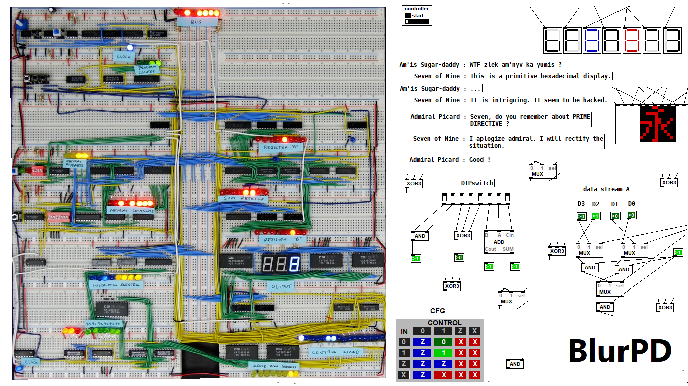
BlurPD - digital logic framework system for Pure Data [v3]
BlurPD is a framework system to extend Pure Data with the ability to make
digital logic circuits while taking advantage of the DSP capabilities of Pure Data. In order to design and simulate interesting circuits, ASIC chips, DSP processors or entire CPU's, all in Pure Data. It is made from jucy fundamental modules (Lego blocks) that when put together turn Pure Data into a madness of bits ...
Bug Fixes & Notes [v3]
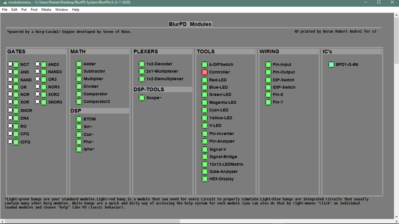
Modules [v3]
- GATES : not,and,nand,or,nor,xor,xnor,cfg,icfg,dna,ro,and3,or3,nand3,nor3,xor3,xnor3
- PLEXERS : 2x1multiplexer,1x2demultiplexer,1x2decoder
- MATH : adder,subtractor,multiplier,divider,comparator,comparator2
- IC : bpd1g8n (integrated 8xNAND gates)
- TOOLS : redled,blueled,greenled,yellowled,magentaled,cyanled,sigv,pininv,gateanalyer
ledmatrix,controller,adipswitch,vled,hexdisplay,sigbridge,pinanalyzer - WIRING : pininput,pinoutput,pin0,pin1,dipswitch,idipswitch
- MODULES : the core library for BlurPD built-in modules
- ICMODULES : the core library for "IC" modules
- DSP : btom,sin~,pha~,ipha~,cos~
- DSPTOOLS : scope~
New Stuff [v3]
- Changes to the Help system. Better GUI and integration [v3]
 patch download
BlurPDv3-[3-7-2020].zip
 BlurPD archive (older versions)
BlurPDv2.9-[3-3-2020].zip
BlurPDv2.8-[3-3-2020].zip
BlurPDv2.7-[3-3-2020].zip
BlurPDv2.6-[3-1-2020].zip
BlurPDv2.5-[2-29-2020].zip
BlurPDv2.4-[2-27-2020].zip
BlurPDv2.3-[2-26-2020].zip
BlurPDv2.2-[2-25-2020].zip
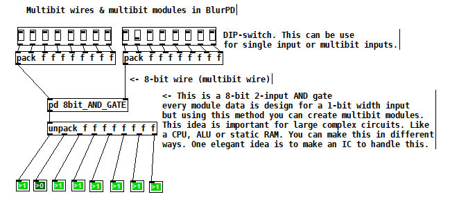
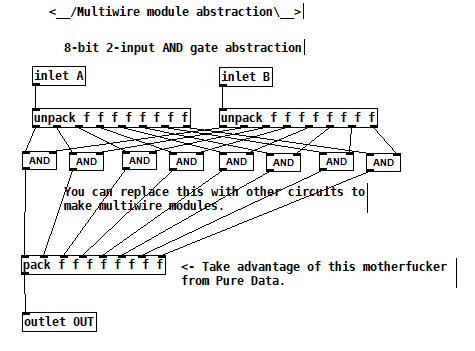
Multibit modules for more complex circuits [v3]
4-bit Boran-Tsung function using a 4-bit ALU (arithmetic logic unit) circuit made with BlurPD [v3]
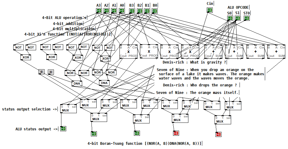
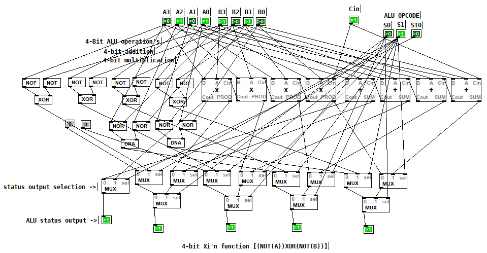
4-bit Xi'n function using a 4-bit ALU circuit made with BlurPD [v3]
Snapshot of the modules system and help system [v3]
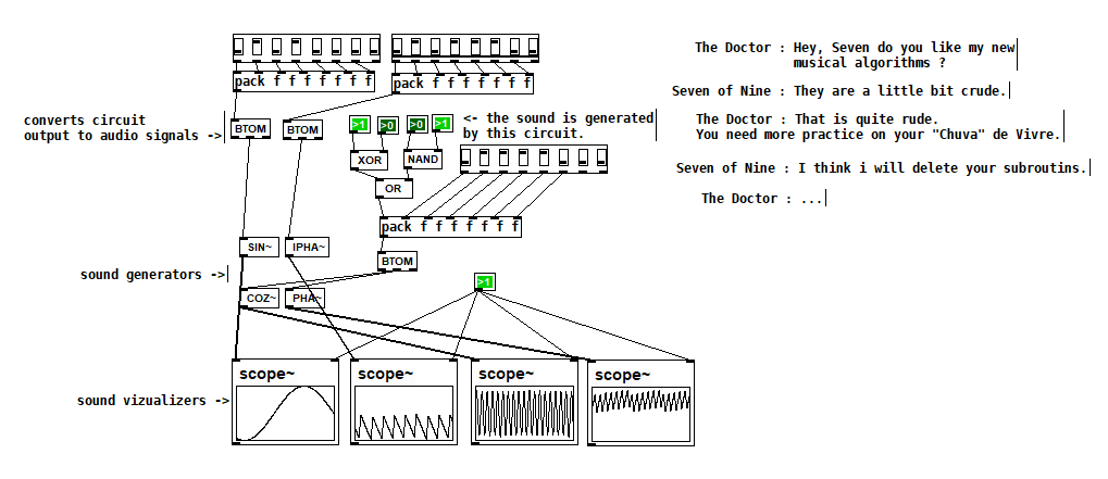
Making generative sounds using new DSP modules [v2.9]
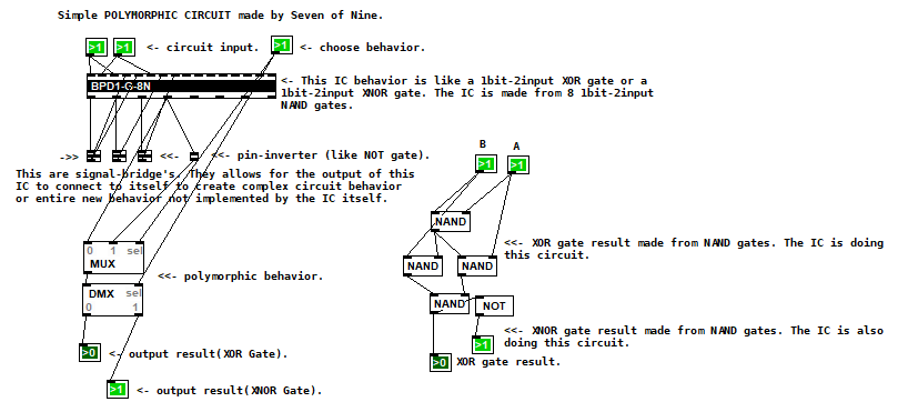
Polymorphic circuit [v2.7]
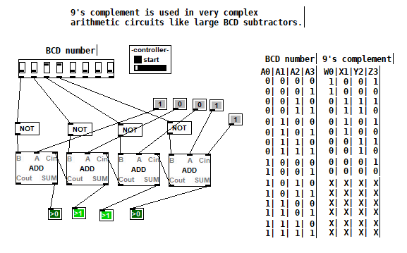
Application 1 of BlurPD system from [v2.3]
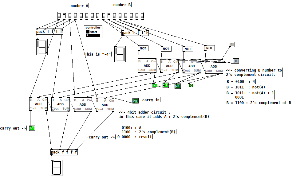
Application 2 of BlurPD system from [v2.3]
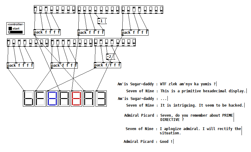
Hexadecimal display [v2.3]
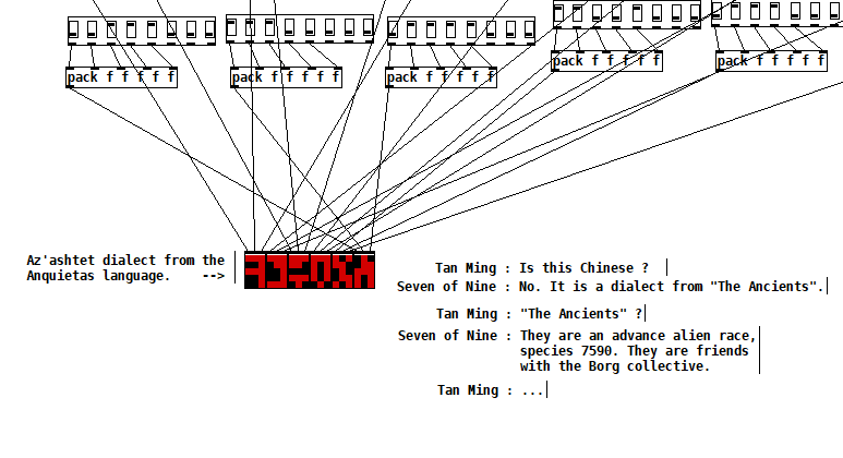
The Ancients [v2.2]
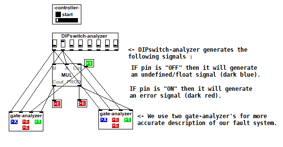
Complex analysis using a DIP-switch analyzer [v2.1]
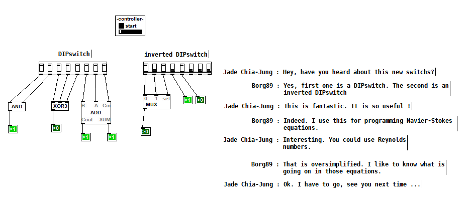
DIPSwitch from [v2.0]
 posted in patch~
Assistance with select function needed...
@Ikeobob I don't know why an "is it equal" test fails with fast changing floats even when the value is printed numerous times.
Someone clever will tell us...... @jancsika
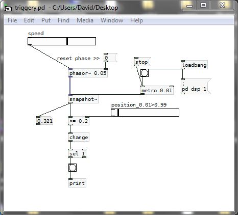
A "greater than" or "less than" test will work, and the [change] object will force the test to trigger only once....... but only on the rising part of the [osc~] curve with a "greater or equal" test.
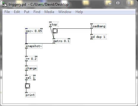
SO....  .... that gets complicated as for a trigger on other parts of the curve a different test would be needed.
The other problem you will have with [osc~] for this application is that a sine wave is not giving you a linear output.... so for timing purposes you are lost.....
You should use a sawtooth wave instead........ so [phasor~] is a better friend than [osc~]...... and as there are only positive values the test can stay the same. You are simply choosing a point on the ramp, and it is linear......
triggery.pd
And then you could be better off using [line] to trigger as the cpu use should be less.
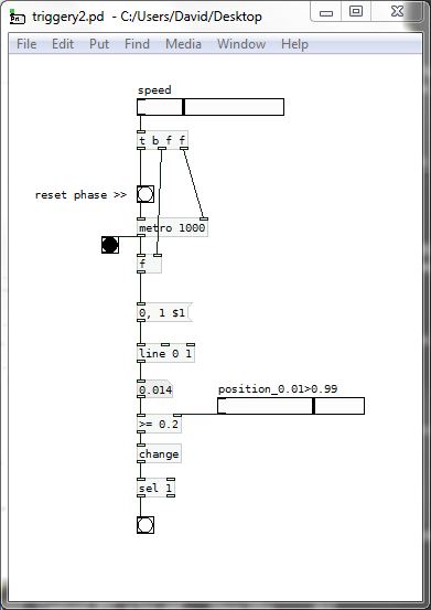
AND...... much better.......
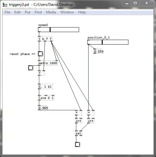
If we scale up the "equals" test to integers then we can test from zero to one and [select] works.......
It should also work with the [phasor~] example above...... BUT..... with [phasor~] you would have to scale in a way that makes sure that a match occurs and that you do not get more than one trigger per cycle.
triggery3.pd
David.
 posted in technical issues
ofelia lua table and a few questions
second try. i commented out the lines where i am not sure if they are a methods (i am quite new to programming except for pure data and a little bit of python). there are only "public:" methods in the list.
class Canvas
  // Canvas(t_symbol *s)
  // Canvas(t_symbol *s, t_floatarg f)
  t_symbol *realizeDollar(t_symbol *s)
  t_symbol *getName()
  int getIndex()
  void getArgs(int *argcp, t_atom **argvp, t_canvas **canvasp)
  void setArgs(int argc, t_atom *argv)
  void getPosition(int **posp)
  void setPosition(int xpos, int ypos)
  t_symbol *getDir()
  void remove()

class Send
  // Send(t_symbol *s)
  void sendBang()sendFloat(t_floatarg f)
  void sendSymbol(t_symbol *s)
  void sendPointer(t_gpointer *p)
  void sendList(int argc, t_atom *argv)
  void sendAnything(int argc, t_atom *argv)

class Inlet
  // Inlet(t_symbol *s)
  void setFloatInlet(t_floatarg f)
  void setFloatInlets(int n, t_floatarg *f)
  void setSignalInlet(t_floatarg f)

class Outlet
  // Outlet(t_symbol *s)
  void outletBang(int index)
  void outletFloat(int index, t_floatarg f)
  void outletSymbol(int index, t_symbol *s)
  void outletPointer(int index, t_gpointer *p)
  void outletList(int index, int argc, t_atom *argv)
  void outletAnything(int index, int argc, t_atom *argv)

class Value
  // Value(t_symbol *s)
  virtual ~Value()
  t_float get()
  void set(t_floatarg f)

class Array
  // Array(t_symbol *s)
  bool exists(t_garray **a)
  float getAt(int n)
  float getAt(int n)
  void getTable(t_word **vecp, int *sizep)
  void setTable(int n, t_floatarg *f)
  int getSize()
  void setSize(long n)

class Clock
  // Clock(t_symbol *s)
  // Clock(t_symbol *s, t_symbol *s2)
  virtual ~Clock()
  void delay(double delayTime)
  void unset()

class Sys
  double getRealTime()
  void lock()
  void unlock()
  int tryLock()
  void gui(t_symbol *s)

class Signal
  int getBlockSize()
  t_float getSampleRate()
  int getInChannels()
  int getOutChannels()
  bool getDspState()

class PD
  int getMaxString()
  int getFloatSize()
  t_float getMinFloat()
  t_float getMaxFloat()
  bool isBadFloat(t_floatarg f)
  bool isBigOrSmall(t_floatarg f)
  tuple<int, int, int> getVersion()
  // int maxString;
  // int floatSize;
  // t_float minFloat;
  // t_float maxFloat;
  // tuple<int, int, int> version;

class Log
  void post(const char *s)
  void post(const char *s, int level)
  void startPost(const char *s)
  void postString(const char *s)
  void postFloat(t_floatarg f)
  void postAtom(int argc, t_atom *argv)
  void endPost()
  void error(const char *s)
 posted in technical issues
ofelia lua table and a few questions
@cuinjune i took a look into ofeliaBindings.h and i tried to make a list of the classes and methods that call internal pd methods.
i am not sure if it is correct / complete but at least it is an orientation for me.
class Canvas
int getIndex()
void getArgs(int *argcp, t_atom **argvp, t_canvas **canvasp)
void setArgs(int argc, t_atom *argv)
void getPosition(int **posp)
void setPosition(int xpos, int ypos)
void remove()

class Send
void sendBang()sendFloat(t_floatarg f)
void sendSymbol(t_symbol *s)
void sendPointer(t_gpointer *p)
void sendList(int argc, t_atom *argv)
void sendAnything(int argc, t_atom *argv)

class Inlet
void setFloatInlet(t_floatarg f)
void setFloatInlets(int n, t_floatarg *f)
void setSignalInlet(t_floatarg f)

class Outlet
void outletBang(int index)
void outletFloat(int index, t_floatarg f)
void outletSymbol(int index, t_symbol *s)
void outletPointer(int index, t_gpointer *p)
void outletList(int index, int argc, t_atom *argv)
void outletAnything(int index, int argc, t_atom *argv)

class Value
void set(t_floatarg f)

class Array
float getAt(int n)
float getAt(int n)
void getTable(t_word **vecp, int *sizep)
void setTable(int n, t_floatarg *f)
int getSize()
void setSize(long n)

class Clock
void delay(double delayTime)
void unset()

class Sys
double getRealTime()
void lock()
void unlock()
int tryLock()
void gui(t_symbol *s)

class PD
int getMaxString()
int getFloatSize()
t_float getMinFloat()
t_float getMaxFloat()
bool isBadFloat(t_floatarg f)
bool isBigOrSmall(t_floatarg f)
tuple<int, int, int> getVersion()
Closing patches without Pd crashing, hopefully in an elegant way...
@nicnut It doesn't seem to be as easy as i previously thought.
Closing other patches isn't a problem, so i consider this solved. But closing the patch that triggers the process seems to be difficult.
There is a very hacky way that works, but is a little bit crazy: close-patches.zip
This works by modifying a secret patch that exists in Pd and close the main.pd patch from within that. A mechanism that checks whether the objects in the hidden patch are already created should be added, if you really want to go down this road.
But i would recommend using the [x]-button that comes with your OS to close the patch.
Edit: The secret patch should never be closed, only hidden. If you close it, graphical arrays will stop working and you will have to restart Pd.
 posted in technical issues
Closing patches without Pd crashing, hopefully in an elegant way...
Hi,
I have a headless Rpi setup using Pd .49.
I am trying to have everything automated, and one thing I'm trying to work out is that I want to close the patch I'm using before I open the next patch. I am doing this by sending internal Pd messages.
I used to quit Pd and re-open it, but due to problems I couldn't resolve after much time connecting my midi controller, I am going to try to just close my patch rather than quit and reopen Pd.
What I've worked out is that every patch will have a [r closepatch] object, and when I want to change patches I will open a patch that will send a bang from [s closepatch] , then it will close itself. I added several seconds of delay time to both patches, but this method always causes Pd to crash.
I am using this message to close a patch: [; pd-mypatch.pd menuclose 1(
My question: How can I close a patch from another patch, and then close the patch that closed the first one? Or is there a better way.
Even better, is there a way that I don't have to enter in the name of the main patch I want to close, like can I use some sort of variable, or send another internal message that will load the patch name into the patch closing message?
I am attatching what I have. First open "closetest1.pd" then "close_patch5.pd" If you connect the messages you can test them properly, but they always make Pd crash on my Rpi.
Thank You.
 posted in technical issues
Audio Settings for multichannel with MOTU 828 mk3
@matthieu1978 Hello......... too late!
@moscardo...........
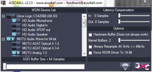
I use the same device. You will need ASIO. I do not remember why, but I ended up using Asio4All as the driver. I think I had some problems with the Motu drivers but.........?
Asio4All lets you make the Windows equivalent of an "Aggregate Device"...... so as many sound cards as you can connect....... !...
Asio4All ..... http://tippach.business.t-online.de/asio4all/
Before you start open the Motu Audio settings and set the samplerate, 64 samples per buffer, Internal master clock, tick "Use stereo pairs for windows audio".
In the second window make sure everything is ticked that you might want to use.
Select ASIO in Pd.
Select Asio4All in the Audio settings window.
Tick to use the ins and the outs......
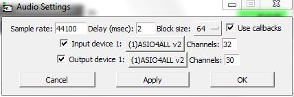
When you have selected Asio4All in Pd then set......
the samplerate you want (must match the setting in the MOTU Audio Console settings
Delay (msec) 2 or 3 should work.
Blocksize 64
Tick the "callback" box
Set 32 in channels (set more if you want to use the built in computer soundcard at the same time)
Set 30 out channels (if more channels... as above)
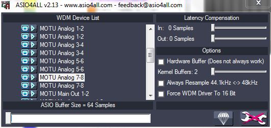
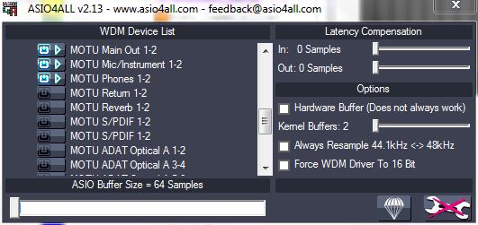
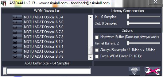
You can now look at the Asio4All setup. A little green arrow icon should have appeared in the bottom right of windows.
Open it, click the "Spanner" and set like this for all the analog channels.
Highlight (click) the boxes at the left side for digital ins and outs and the inserts and reverb returns if you want to use them them.
Even if the inputs (or outputs) are not in the correct order, they will stay the same, even after re-plugging the soundcard, rebooting the computer, and re-starting Pd.
posted in technical issues
Build a MIDI controller with the Arduino, Firmata and Pure Data
Time to start contributing some knowledge back to the wonderful world that is the internet; today, a step by step nice and easy tutorial on getting started to building your own MIDI controllers with the arduino.
When researching for my ableton controller project, I didn’t find much out there about using firmata on an arduino to send data to software. The standard approach just seemed to be create the code in the arduino language, upload it to your board and hack one of those MIDI to USB cables as a bodge job way of getting the MIDI out of the arduino.
So why firmata and pure data? Well the whole idea of firmata is that you flash it to your arduino, and it throws out serial about whats going on with the arduino inputs and outputs, then you decide how the software treats the readings coming in and going out.
Theory out the way, lets build some controllers. You’ll need a few things…
HARDWARE:
An arduino and something to wire into it (for this i’ll be using a pot)
A USB cable for your arduino
SOFTWARE:
Arduino – http://arduino.cc/en/Main/Software
Pure Data – http://puredata.info/downloads
Firmata – http://at.or.at/hans/pd/objects.html#pduino
Something to patch your new controller into; like Reason or Ableton Live
- SETTING UP FIRMATA AND PURE DATA
Install Pure Data and create a folder to store all your patches somewhere. Unzip Firmata and add the files ‘arduino.pd’, ‘arduino-test.pd’ and ‘arduino-help.pd’ to your new Pure Data folder. The ‘arduino.pd’ file is the object that we use in PD for opening up communication with your arduino and routing it to PD. Done? Awesome, your software is almost set up.
- FLASHING FIRMATA TO YOUR ARDUINO
Install the latest version of arduino and open it up. Connect your arduino with the USB cable to your laptop (i’m using a macbook for this by the way). In the example patches, open up “Standard Firmata”, select your board (im using an arduino mega), and your serial port (look for tty.usbserial for use with a USB cable). Then compile and hit the upload button and your arduino is now ready to use firmata and communicate with Pure Data!
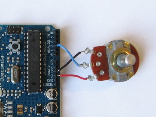
- WIRING UP A POT
Potentiometers are cool, and theres a great arduino tutorial of how to wire one up here: http://www.arduino.cc/en/Tutorial/Potentiometer
Basically, all you need to know is that there are three pins; your two outer pins govern voltage flow across the pot, meaning one has to be 5V and the other has to be ground. It doesn’t matter which, but your 5v pin is going to be where your pot reads maximum, so convention dictates this should be the right hand pin. The center pin needs to be connected to an analog in on the arduino and will read the value of the pot as it sweeps from ground (0v) to 5v.
All wired up? Plug it into your laptop and open Pure Data, we’re ready to get things talking.
- SETTING UP OUR PATCH
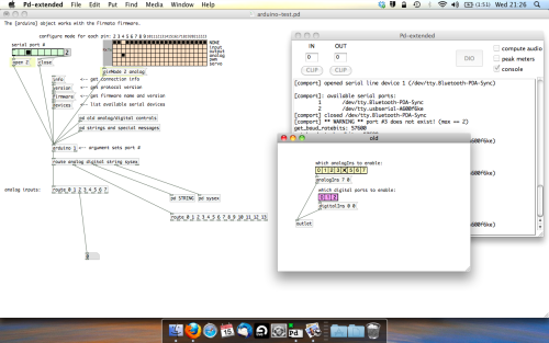
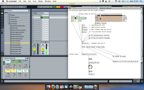
Open the example “arduino-test.pd” Pure Data patch you copied over earlier. It should look like this one…
The test patch has everything we need to open a connection and enable pins. Firstly, lets delete a bunch of stuff and make our window a bit bigger. Hit Command + E to enter edit mode in Pure Data.
Ok a quick explaination; the key component here is the ‘arduino’ object. This is being drawn from the file you copied in earlier, and is what communicated with your arduino. Here we can do everything to control the arduino from opening a connection, to receiving data.
The large grid allows us to set the mode of each pin on the arduino. Remember pins 0 and 1 are reserved for Rx and Tx. I’m using analog pin 4 for this demo, so I’ve set my pin mode for pin 4 to ‘analog’.
Now we can plug our arduino in and get a reading from the potentiometer.
- ARDUINO INTO PURE DATA
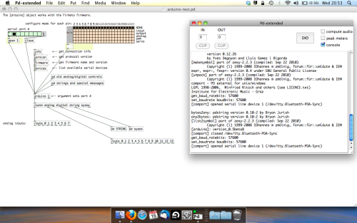
With your arduino plugged in, hit command and E to bring us out of edit mode. In our patch, click on ‘Devices’ above the arduino object and open up the pure data terminal. (That other thing that loads with PD that has all the scary code in)
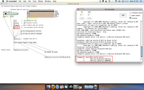
The “Devices” message connected to the arduino object pings your computer to find what devices are connected and on what serial ports. Since we’re using a USB cable to connect our arduino, we’re looking for something with ‘usbserial’ in it, in this case; port 2.
Select the relevent port in the green box at the top (remember the first box is ‘0’, second is ‘1’ and so forth) and hit ‘Open’ to establish a connection. Check the terminal to see if the connection was sucessful.

Now lets check we’re getting something in. Create a number box (Command + 3) and connect it to the relevent pin on the ‘Route analog’ box at the bottom. In this case, pin 4.
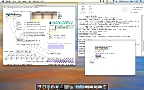
One more thing; if you’re not getting any readings in, you’ll need to click on ‘pd old analog/digital controls’ and enable your pins here too. What I tend to do in my patches is just not include the large grid but make my own ‘old pd’ controls custom to what i’m enabling/disabling to save space.
Here’s what the ‘old analog/digital controls’ subpatch looks like (pin 4 enabled)…
Come out of edit mode and check that you’ve got readings. If so congratulations! If not, troubleshoot, start with making sure your usb connection is opened, make sure all the correct pins are enabled (remember you’re counting from 0 not 1 on most of these buttons in PD, it’s just the way computers work).
- SCALING READINGS TO MIDI
So we’ve got a reading and chances are it’s to 3 decimal places between 0 to 1. No problem, create a new object (Command + 1) and type “autoscale 0 127”. This allows us to scale the input to a min and max value, in this case 0 to 127 of MIDI. Next, lets get things looking nice, create a new object and type “knob”. Connect this AFTER the autoscale object. (the knob is default set to read inputs from 0 to 127. Then create another number to display the scaled MIDI data coming out, and finally a new object and type “ctlout 1”.
It should look something like this…
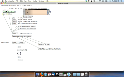
The second box should be outputing values from 0 – 127 now, and the knob giving a visual representation of your potentiometer.
Now lets patch it into ableton…
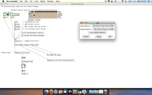
- PURE DATA TO ABLETON LIVE
Firstly, you’ll need to set up your macs IAC driver if you’ve not done this. Basically you’ll need to go into Audio/MIDI preferences and enable your IAC driver. Then create a new input and output. One for input to DAW and one for output from DAW. Google around for a tutorial on this, its really simple, a 30 second job.
After you’ve set up your IAC driver, go back to PD and go to preferences > MIDI Settings, and connect your IAC driver.
Open ableton and go to its MIDI preferences. Create a device listing for your IAC driver and enable its ins and outs into ableton like so…
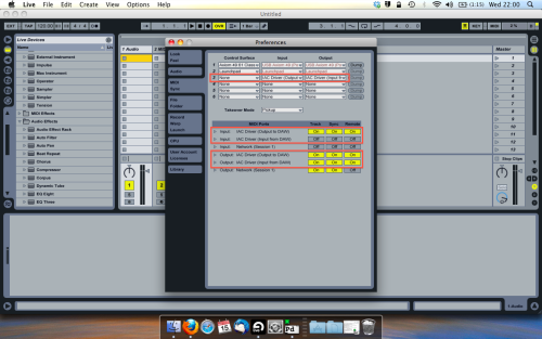
And thats it! Create an instrument and try to assign something! I’ve got it controlling the brightness of a bass sound here.
Shout out for Facu who requested this tutorial. Hopefully it’ll help some of you looking to get into this stuff and start building things but with no idea where to start.
 posted in tutorials