-
 MarcoDonnarumma
posted in news • read more
MarcoDonnarumma
posted in news • read more@timothyschoen I see, thanks for the explanation of the process, it makes sense.
Look forward to dive more into PlugData.
-
 MarcoDonnarumma
posted in news • read more
MarcoDonnarumma
posted in news • read moreTruly awesome project @timothyschoen !
I installed the previous version last week and had an overall good experience with basic patches, with some minor issues that hopefully I find time to post to the tracker in github.In any case, thanks so much for doing this! Among the previous attempts to make alternative GUIs for Pd, yours stands out.
I was almost moved when I run it on my laptop after using Pd for 20 years, this is something to behold eheheh
While for long-time users like me it may be tricky to completely switch from Pd-Vanilla to a new GUI, I think the kind of work you are doing will be very helpful to Pd in the long run, especially in helping beginners not to feel intimidated by the trademark, stern GUI of Pd
 and instead enjoy its community, potentials and quirks
And I can think of several use cases where a user who normally works in Pd-Vanilla would find useful to have the possibility to transfer patches to PlugData: like, creating easily readable patches and plugins for third party use, or artwork packages ready for exhibitions, etc... exciting.I am curious about the strong resemblance to Max; is it something planned for a particular reason or it was merely used as a quick reference?
It would be even nicer to have a GUI that is unique to Pd, but that's just an aesthetic point lol Nothing to take away from your work!
 -
 MarcoDonnarumma
posted in technical issues • read more
MarcoDonnarumma
posted in technical issues • read morehey @whale-av @manuels @jameslo thanks once again for the feedback! I think we are getting there, very exciting. I just quickly plugged your suggestion into my patches and they both work well. Interestingly enough now the sig~ and the resampling method result in two sounds that are timbrically quite different, but still coherent with what I would expect. This is super interesting, even as a creative toolset, as long as the difference in timbre are not artefacts. I will investigate this further and try to post some audio examples.
Gonna work more on the project this week and keep you posted. Just bear with me as I cannot work on this full-on every day like the past weekend, cause of other commitments.
@jameslo sorry to hear, it is quite jumping around these days, I hope your symptoms are bearable, and I'm glad that an interesting problem can help a little

@whale-av the vline~ there is very elegant! I had previously tried with a line3 in the control domain but your suggestions makes more sense. I've used a bucket object to get the interval, that should be the same as what you are doing in your patch.
@manuels yes, indeed. Different filters are the next thing I'm gonna look into, especially as I gonna need a more systematic spectral analysis of the resulting sound to make sure it is still coherent with the expected signal.
-
 MarcoDonnarumma
posted in technical issues • read more
MarcoDonnarumma
posted in technical issues • read more@jameslo I think you understood everything correctly! I think David and I were just trying to clarify the problem in that early post.
-
 MarcoDonnarumma
posted in technical issues • read more
MarcoDonnarumma
posted in technical issues • read moreHello, here's an update, this is where I am at:

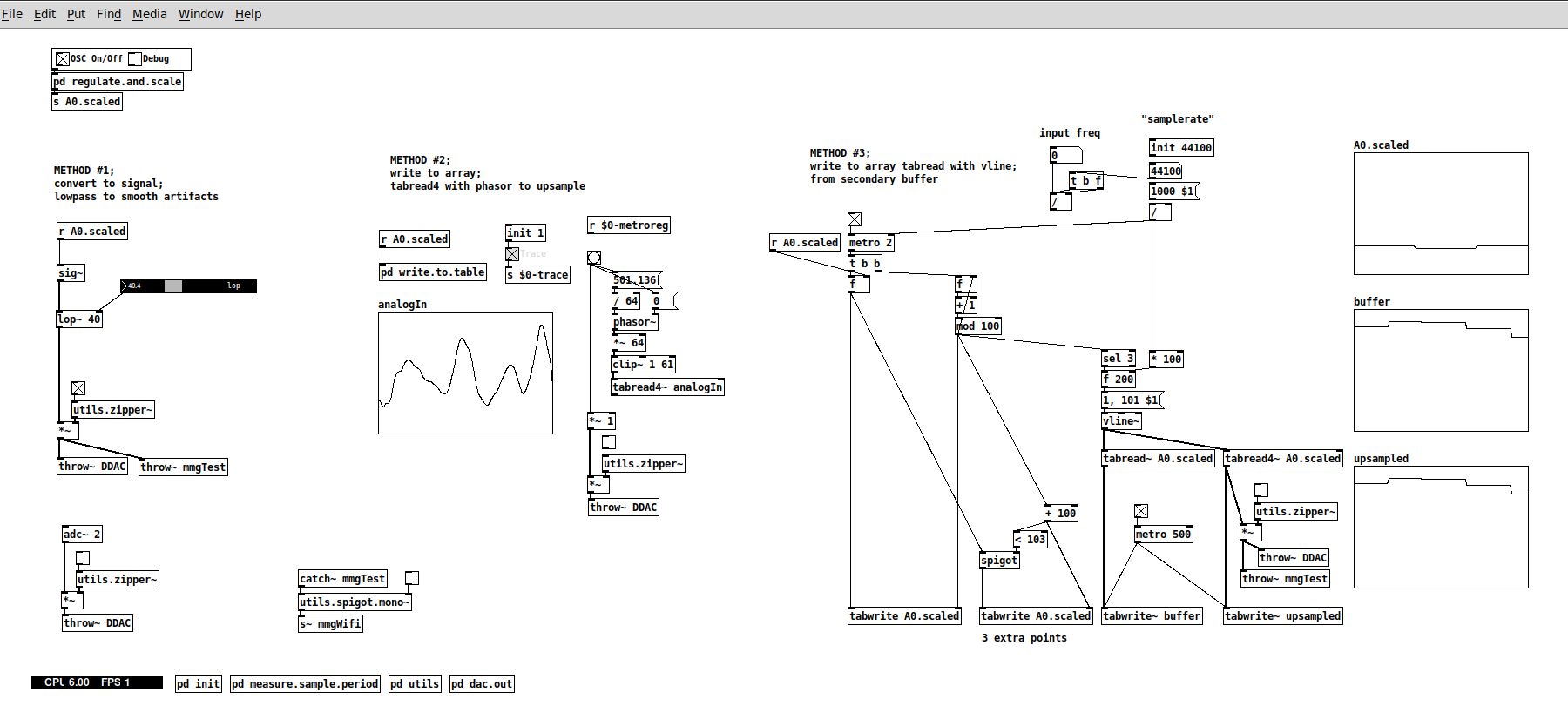
Method #1 with sig~ and lop~ @whale-av
- this works now quite well now. A lop~ at 40 actually hits a sweet spot for the kind of sounds I need to pick up with the mic. Not sure why though. The resulting output is still a bit "noisy", but works well with my patches for the standard XTH Sense, where I use the same mic, but wired. So, this is very good.
Method #2 with tabread4~ @jameslo
- I didn't manage to make it work merely because I didn't understood it fully, not because of the method per se, which looks sound. I didn't put too much work on this, since method #3 seems to be an extension of this, so I focused on the latter.
Method #3 with tabread4~ and vline~ @manuels
- This works well in my patch above, but strangely enough the upsampled signal still presents the steep steps. The output signal sounds as the output from sig~ from method #1. So here I may have missed something in the implementation? or perhaps is the lack of timestamp...
Updates on other solutions we discussed:
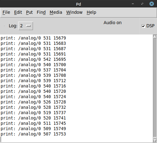
- timestamp: I did manage to get a timestamp using the millis() function, which I think should be enough for this use case. This simply counts ms passed from the moment the board has been switched on and attaches it to each reading

- Increasing the sampling rate on the arduino rp2040 with the microcontroller of the same name seems pretty unexplored (at least after one day of investigation on forums etc..). I need to look more into it. But considering what David pointed out about the brickwall at 689Hz, maybe this is not even an option here.
- FYI, on ARM microcontrollers it is possible to use prescalers, bypass analogRead and read analog data directly from the hardware using register calls at quite fast rates (some people managed to almost 40.000). But I chose the rp2040 for its dimensions, its wifi connectivity (and, partially, for the onboard machine learning features). So if anyone knows of another off-the-shelf board that uses ARM and has similar dimensions and connectivity, please point it to me
 I'll check too of course.
Next steps:
- as it stands, method #1 works well with my patches too and I could just lay back and test this further with my performance software. Especially since by applying the audio signal conditioning and processing I have in my software, the difference with the wired signal is not seriously noticeable and the wireless is even more responsive and less prone to artifacts
- BUT! I would really like to get the upsampling work since it is potentially the most technically sound solution. So I would like now to work more on this using vline~ with the timestamp. A pointer in that direction would be great, since admittedly arrays and tabreads are one of my weak spot in Pd.
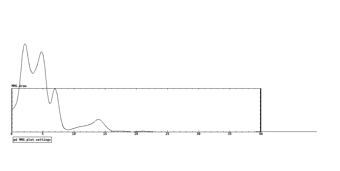
P.S. A clarification, before I stated 40Hz as the max. frequency I need to capture, but, to be precise, the range of muscle sounds (including heartbeat and blood flow) is between 1-25/30Hz, as you can see from this pic (a magnitude spectra of the output signal from lop~ capturing a forearm contraction)

-
 MarcoDonnarumma
posted in technical issues • read more
MarcoDonnarumma
posted in technical issues • read moreHey @whale-av @jameslo @manuels just dropping a note that all your suggestions are very interesting and I'm gonna work today on implementing and comparing them (got some mileage yesterday refining the patch with sig~ and lop~ with some decent results, next will try the tabread~ options).
I would like to do then a round up and post some results here, then see where to go from there.and David, yes, I love and am grateful to see other people thinking with me in real time, that's the beauty of these kind of things

Thanks!
M -
-
 MarcoDonnarumma
posted in technical issues • read more
MarcoDonnarumma
posted in technical issues • read moreThanks @whale-av David, several good pointers in your reply.
The sampling period is continuously updated. It's a basic method using fifo and timer. Do you perhaps have suggestions for a more precise measurement technique?
Yes, you are right, the clocking issue may be where to look into first. Incoming values are not regulated yet, I'll get down to do that now (was hoping to get a more or less stable sampling period from the arduino, probably naive.) And thanks for the link!
and now that I read you about tabwrite~ I see that I always understood it wrong
 Thanks.
to your P.S.: Yess, that sounds like one of the things I was missing. It could be. If this is the case, the patch is fine and the problem is the low sampling rate, then I can see two options:
- increase the sampling rate in the arduino. I found this tutorial that gets you, allegedly, at 38.5kHz sampling rate on analogIn
or - would it make sense to prepare the signal in a subpatch with a low sampling rate matching the arduino's and then in a parent do upsampling and interpolation before sending out to processing?
Ok, gonna work on it and come back with updates.
Marco - increase the sampling rate in the arduino. I found this tutorial that gets you, allegedly, at 38.5kHz sampling rate on analogIn
-
 MarcoDonnarumma
posted in technical issues • read more
MarcoDonnarumma
posted in technical issues • read morethanks @alexandros, yes, that's the first thing I tried, but I gets only noise, seeing the shape of the wave in an array it seems there's something wrong about either the sampling rate or the bit resolution...?

-
 MarcoDonnarumma
posted in technical issues • read more
MarcoDonnarumma
posted in technical issues • read moreHi all,
this feels like a trivial problem, but I can't get my head around it.
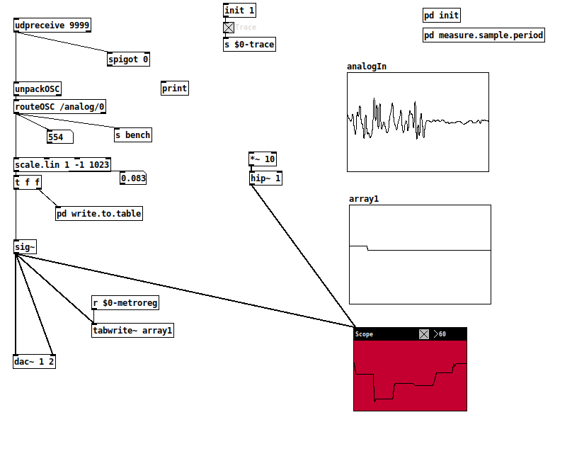
I've got an electret mic connected to the analogIn of an arduino rp2040 connect. I'm sending the analogIn values via WiFi over UDP as OSC. I get the data in Pd and I would like to "reconstitute" the mic sound from the analog reading.I'm familiar with how ADC works, but either I'm stupid or there's something I'm missing and I can't figure out how to go about this in Pd.
Some details:
- the mic output goes through a breakoutboard amp, so the signal arriving into the arduino is already DC Offset and centered nicely between 0 and 1023
- the signal is handled in Pd with a sampling rate of 500hz (according to my measurement), which should be fine for the low frequency sound I'm producing into the mic (sounds won't be higher than 40Hz)
- why I don't simply use a wireless audio transmitter? it's a long story, but this relates to making my long-running XTH Sense biosensor wireless. In the past years I tried many different options to no avail (including making a startup and producing a custom wireless audio hardware), and I came to the conclusion that the project needs the simplest and more reliable ever implementations, if others are really to continue use it.
Any hint is greatly appreciated!
thank you,M

 see it now