Objects for formant synthesis?
So, how about we discuss all these options and how they relate to each other? Anyone with me?
Let me talk about FOF here... Basically, it's a hard-synced oscillator! And I always thought hard synced oscillators sounded really nice for forcing harmonics into a fundamental pitch, and that's it... Ok, there's more to that of course, and it also passes through a decay envelope, which can be implemented with [rpole~], here's a minimal Pd patch of this main core.... it uses objects from ELSE of course... specially for making hard sync easier. Below, 150 is 'f0' (fundamental), 390 is center/formant frequency, and 100 is bandwidth, all in Hertz...
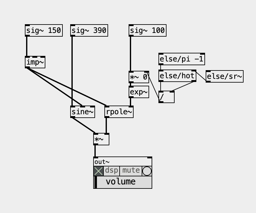
But then, the envelope grain might and can overlap. The Csound implementation is pretty much "Csoundy", ridiculously complicated with way too many parameters and options, not to mention a seemingly inexplicable low output that forces you to multiply it by a ridiculously large and arbitrary number. Besides the decay envelope, it also applies another envelope on top of it, which might be pretty useless when the first envelope simply dies before it, but it can be useful to apply an attack phase. What a mess! The FAUST implementation is simpler and makes more sense!
The Formlet UGen from supercollider implements a filter with attack and decay, and it rings, so you don't need the hard synced oscillator. Plus, it can "overlap" grains quite seeminglessly. It's pretty clever and it made its way back into Csound, where it's called fofilter.
What makes no sense for me is the "BandWidth" parameter in FOF (or using Formlet). In Pd's examples we have the paf like patches and the bandwidth makes actual sense because it represents a bandwidth of partials over the center frequency. In FOF we don't have that ") and the larger the bandwidth, the thinner the sound actually is because the decay is faster.
and the larger the bandwidth, the thinner the sound actually is because the decay is faster.
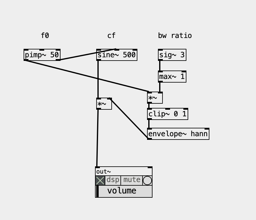
Now, i also ported the Formant UGen and this is what it is, basically, as a patch, guess what? Yup, another hard synced oscillator, basically, being enveloped, so... I guess it relates to the Fof approach... but not quite... one way or another, there's no reference in the docs or code of where it comes from and maybe I should ask the SC Forum (again) Below, BW ratio means the ratio of bandwidth according to the fundamental, so '3' is '150' hz. This parameter to me feels like controlling the "brightness" anyhow.
And there are also the FM approach, the paf, the VOSIM, not to mention the filterbank approach... Gosh, what a mess... I guess I know why I procrastinated so much to finally deal with this... but it's time and now I'll map them all and see how they relate to each other. And I'll sort it all out in my Live Electronics Tutorial...
I'm still thinking what are the objects that make sense actually including in ELSE...
 posted in technical issues
line (or timed ramp generator) trouble
@willblackhurst It's all numbers in a computer... digital.
As simply as possible.........
Tilde objects set processing of the digital audio thread in Pd. The digital audio is a stream of numbers representing the height of the equivalent analogue signal wave..
These numbers only become a voltage..... an analogue waveform when they are passed to the DAC... the digital to analogue converter.... your soundcard output.
The ADC is where the analogue signal is converted to numbers for input to the digital audio thread.
Audio files are stored on the computer disk as numbers.....
The numbers are read, streamed, processed and output at the sample rate.
The not simple answer can be found searching for FFT.
David.
 posted in technical issues
Simple Vanilla Tube Waveguide
I wanted to share this simple vanilla tube waveguide I wired up based on an example from Dodge & Jerse's Computer music: synthesis, composition, and performance: https://github.com/brianlindgren/dodge-jerse-tube
I was teaching Pd synthesis class & was surprised how hard it was to find vanilla waveguide models for Pd. I stumbled upon the ACRE Waveguide Library, but lots of externals needed. Anyone know of vanilla waveguide models ppl have shared online?
 posted in abstract~
"Return to caller" (followup from "symbols explicit")
grep " goto " pd-0.55-1/src/* | wc -l
283
There might be one or two comments in there but those are predominately literal gotos. Goto being discouraged is a holdover from BASIC which originally only had goto for moving about in code, it had no functions and literally executed code line by line, as BASIC developed and got other ways to control execution they discouraged the use of goto. In any language with functions or objects etc there is no need to discourage the use of goto since no one is going to try and control program execution through goto for any reason other than an academic exercise. A goto is just telling the IP to goto a remote place in the program code instead of the next instruction, happens everytime you run a function. The most basic implementation of a function:
function f (a b) {  -- push current address to return stack, pop a and b from data stack, set a and b, goto f
    c = $a+$b -- execute f
    return $c -- push c to data stack, pop address off return stack and goto it
}
Generally stacks only hold one data type so we would also have to set the return type in the function header function int f (a b) so return knows which stack to push to. Higher level languages just do all this stuff for you. In pd it would be the outlets which are the gotos, outlets are structs which hold pointers to tell pd where to goto next. Possibly the pointers in the outlet struct might just be used for telling the GUI how to draw the wires, depends on how it is implemented and I can think of at least a half a dozen different ways it could be implemented to the same ends. If the stack only holds pointers to objects it is easy for pd to function without a return stack, when it hits a branch it pushes the pointer for the branch, goes down the branch pushing the pointer for each object, pops each to execute (possibly each being another goto) finally popping the return and does the goto to the branch point to do the next branch. The object way I outlined above accomplishes the same thing but I believe it would be a bit more efficient, in that case the stack could be a data stack or a pointer stack which also holds pointers to data.
Back when I was last trying to sort this out I ended up digging into [trace], it actually has its own stack (possibly two, did not deeply analyze it since it was not what I was looking for). When you turn tracing on it enables tracing in EVERY object on the canvas and they all send their messages back to [trace] which puts them on its stack. This is why enabling trace slows down message passing, also why it took so long for [trace] to get implemented, not so simple as just printing what is on the stack. I think the second stack in [trace] might be a pointer to the pd stack and it uses pd's stack to determine which messages to print and maybe gets part of its data from the stack but as I said, I did not dig into it too deeply and that was awhile back. I suspect pd's stack is a pointer stack but I am not sure if it only holds pointers to objects or also pointers to data, if the latter single stack returns could be more troublesome.
there are a few legit ways to use them, but otherwise, don't; same for gotos.
In my experience they are generally used for blocks of code which you need to reuse often but do not work well within the context of a function or the like, would need to be broken up into dozens of small functions which would make the code difficult to read and inefficient to run because functions have good deal of overhead and generally have scope and limited in what they can return. Gotos also have the advantage of being able to return to somewhere other than from where they were called from, which can also help makes things more efficient, depends on the language and how things are implemented. In some languages goto is slightly different in different contexts, in a loop it is the same as break and goto and in a function it is return and goto, etc.
 posted in technical issues
Pd compiled for double-precision floats and Windows
@jameslo said:
@ddw_music So in the case of c#, Pd64 and SC, are the non-zero numbers past the precision limit real?
lacuna beat me to the punch, but I already wrote some stuff up from a slightly different perspective. Maybe this will fill in some gaps.
In short: Yes, those "extra digits" accurately reflect the number that's being stored.
Sticking with single precision... you get 1 sign bit, 8 exponent bits, and 23 mantissa bits (for 24 bits of precision in the mantissa, because in scientific notation, there's one nonzero digit to the left of the point, and in binary, there's only one nonzero digit, so it doesn't have to be encoded).
Binary long division: 1 over 1010 (1010 = decimal 8+2 = decimal 10).
       0.00011001100....
      __________
1010 ) 1.0000 - 16/10
         1010
         ----
          1100 - remainder 6, then add a digit = 12/10
          1010
          ----
          00100 - remainder 2, then add a digit = 4/10
            1000 - 8/10
            10000 - 16/10 repeating from here
= 1.10011001100110011001100 * 2^(-4)
The float encoding has a finite number of digits -- therefore it must be a rational number. Moving the binary point 23 places to the right, and compensating in the exponent:
110011001100110011001100 * 2^(-27)
= 0xCCCCCC / 2^27
= 13421772 / 134217728
Just to be really pedantic, I went ahead and coded step-by-step decimal long division in SC, and I get:
~longDiv.(13421772, 134217728, maxIter: 50);
-> 0.0999999940395355224609375
... which is below the IEEE result. That's because I just naively truncated the mantissa -- I think IEEE's algorithm (when populating the float in the first place, or when dividing) recognizes that the next bit would be 1, and so, rounds up:
~longDiv.(13421773, 134217728, maxIter: 50);
-> 0.100000001490116119384765625
... matching lacuna's post exactly.
Division by large powers of two, in decimal, produces a lot of decimal digits below the point -- but it will always terminate.
hjh
 posted in technical issues
Pd compiled for double-precision floats and Windows
@jameslo said:
@ddw_music I love that story but am scratching my head over the 1/10 example you gave. Here's a test I made in Arduino c++: ... I went out 40 digits and didn't see anything unexpected. Was that example you gave just a metaphor for the issue, or is my test naive?
Not a metaphor at all:
[16, 17, 40].do { |prec|
    "% digits: %\n".postf(
        prec,
        0.1.asStringPrec(prec)
    )
};

16 digits: 0.1
17 digits: 0.10000000000000001
40 digits: 0.1000000000000000055511151231257827021182
As for Arduino, the float datatype reference says "Unlike other platforms, where you can get more precision by using a double (e.g. up to 15 digits), on the Arduino, double is the same size as float" -- so my guess here is that Serial places a limit on the number of digits it will try to render, and then fills the rest with zeros.
I went out 40 digits and didn't see anything unexpected.
Seeing zeros all the way out to 40 digits is unexpected! Arduino's output here is more comforting to end-users (which might be why they did that), but it isn't accurate.
Considering that Arduino calculates "double" using single precision, the output should deviate from the mathematically true value even earlier:
// 0.1.as32Bits = single precision but as an integer
// Float.from32Bits = double precision but based on the 32 bit float
Float.from32Bits(0.1.as32Bits).asStringPrec(40)

-> 0.100000001490116119384765625
The most reasonable conclusion I can draw is that Arduino is gussying up the output to reduce the number of "what the xxx is it printing" questions on their forum. That should not be taken as a standard against which other software libraries may be judged.
Edit: hmm, but here's Pd64.
Pd64 is doing it right, and Arduino is not.
Getting back to how Pd seems to differ from other programming languages, I'm going to hazard a guess and say that Pd hasn't separated the value of a float from its display/storage format.
The value must be stored in standard single/double precision format. You need the CPU to be able to take advantage of floating point instructions.
It's rather that Pd has to render the arguments as text, and this part isn't syncing up with the "double" compiler switch.
PS I hope my attempt at humor didn't discourage @porres from responding to @oid's question. I'm sure he would have something more meaningful to contribute.
Of patchers as programming languages... well, I got a lot of opinions about that. Another time. For now, just to say, classical algorithms are much harder to express in patchers because patchers are missing a few key features of programming languages.
hjh
posted in technical issues
Ultrasonic distance sensors with Pd in Bela
The ultrasonic distance sensors are usually digital, not analog. If this is the case, you're trying to read a digital signal as analog, which doesn't make much sense. This sensor has two pins, a trigger and an echo. You have to send a high voltage to the trigger pin, then pull it low, and read the echo pin which will help you compute the distance based on the time it took for this trigger pulse to arrive back at the echo pin.
The code below (copied from Arduino'g Project Hub), uses Arduino's pulseIn() function, to compute the distance:
// Define Trig and Echo pin:
#define trigPin 2
#define echoPin 3
//  Define variables:
long duration;
int distance;
void setup() {
  // Define  inputs and outputs:
  pinMode(trigPin, OUTPUT);
  pinMode(echoPin, INPUT);
  //Begin Serial communication at a baudrate of 9600:
  Serial.begin(9600);
}
void  loop() {
  digitalWrite(trigPin, LOW);
  delayMicroseconds(5);
  digitalWrite(trigPin,  HIGH);
  delayMicroseconds(10);
  digitalWrite(trigPin, LOW);
  // Read  the echoPin, pulseIn() returns the duration (length of the pulse) in microseconds:
  duration = pulseIn(echoPin, HIGH);
  // Calculate the distance:
  distance=  duration*0.034/2;
  // Print the distance on the Serial Monitor
  Serial.print("Distance  = ");
  Serial.print(distance);
  Serial.println(" cm");
  delay(1000);
}
I searched online and found the source of this pulseIn() function in Arduino's forum, which is this:
/*
  wiring_pulse.c - pulseIn() function
  Part of Arduino - http://www.arduino.cc/

  Copyright (c) 2005-2006 David A. Mellis

  This library is free software; you can redistribute it and/or
  modify it under the terms of the GNU Lesser General Public
  License as published by the Free Software Foundation; either
  version 2.1 of the License, or (at your option) any later version.

  This library is distributed in the hope that it will be useful,
  but WITHOUT ANY WARRANTY; without even the implied warranty of
  MERCHANTABILITY or FITNESS FOR A PARTICULAR PURPOSE.  See the GNU
  Lesser General Public License for more details.

  You should have received a copy of the GNU Lesser General
  Public License along with this library; if not, write to the
  Free Software Foundation, Inc., 59 Temple Place, Suite 330,
  Boston, MA  02111-1307  USA

  $Id: wiring.c 248 2007-02-03 15:36:30Z mellis $
*/

#include "wiring_private.h"
#include "pins_arduino.h"

/* Measures the length (in microseconds) of a pulse on the pin; state is HIGH
 * or LOW, the type of pulse to measure.  Works on pulses from 2-3 microseconds
 * to 3 minutes in length, but must be called at least a few dozen microseconds
 * before the start of the pulse. */
unsigned long pulseIn(uint8_t pin, uint8_t state, unsigned long timeout)
{
    // cache the port and bit of the pin in order to speed up the
    // pulse width measuring loop and achieve finer resolution.  calling
    // digitalRead() instead yields much coarser resolution.
    uint8_t bit = digitalPinToBitMask(pin);
    uint8_t port = digitalPinToPort(pin);
    uint8_t stateMask = (state ? bit : 0);
    unsigned long width = 0; // keep initialization out of time critical area

    // convert the timeout from microseconds to a number of times through
    // the initial loop; it takes 16 clock cycles per iteration.
    unsigned long numloops = 0;
    unsigned long maxloops = microsecondsToClockCycles(timeout) / 16;

    // wait for any previous pulse to end
    while ((*portInputRegister(port) & bit) == stateMask)
        if (numloops++ == maxloops)
            return 0;

    // wait for the pulse to start
    while ((*portInputRegister(port) & bit) != stateMask)
        if (numloops++ == maxloops)
            return 0;

    // wait for the pulse to stop
    while ((*portInputRegister(port) & bit) == stateMask) {
        if (numloops++ == maxloops)
            return 0;
        width++;
    }

    // convert the reading to microseconds. The loop has been determined
    // to be 20 clock cycles long and have about 16 clocks between the edge
    // and the start of the loop. There will be some error introduced by
    // the interrupt handlers.
    return clockCyclesToMicroseconds(width * 21 + 16);
}
This is already getting complicated, as pulseIn() uses other functions which should be found and translated to Pd. I guess the best thing you can do is try to translate the first code chuck in this reply to Pd, and when you read a high voltage in the echo pin, do some math to calculate the distance.
In essence, set a digital input and a digital output pin on the Bela, trigger the output pin with a high and low signal, and keep reading the input pin (you should probably use a pull-down resistor there), until you get a high. Calculate the time it took with the [timer] object and do some simple math to get the distance. Do that with distances you know first, and then use the rule of three based on the known distance and the time you get. At least, that's how I would try to get this to work.
Another solution is to use an infrared proximity sensor, which is analog, and it's probably much easier to use. But this gets the proximity of obstacles right in front of it only, while the ultrasonic range finder has a wider field where it can detect obstacles.
 posted in technical issues
trying to build a waveguide and am lost how to solve the DSP Loop error
Perhaps you can give me some insight on how pure data calculates, i am kinda lost in debugging this issue.
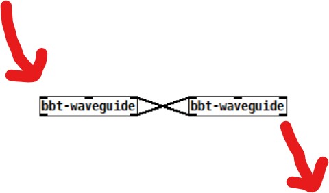
I want to do a waveguide simulation,In short the signal goes in, gets delayed, reflected on the and with some dampening and gets delayed again with some dampening. In the end you got 2 inlets and 2 outlets (front and back of the pipe). When you connect two waveguides together the reflection feed into each other.
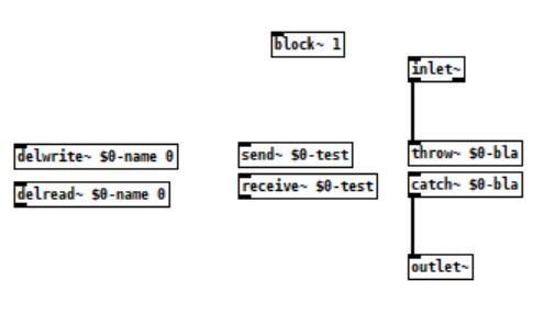
I searched the forum about DSP Loop error and other people trying to implement a Waveguide, but I still can't solve it. I read about how pd does 64 sample blocks and you need to set them to one, which i did. And that i need to add a throw/catch or similar (i tried multiple) to force instant calculatins, but i dont really understand why or how (beside adding block~ 1) the implemetation works. Especially where do i need to do the 1-sample delays to force the calculation.
Prior using pd I implemented my idea using python (but its to slow) and luckily i found pure data which is a godsend so far! Strange that iam doing music for over a decade and never heard of it... Because of the Python implemetation I understand it in a technical standpoint, but not how i can do it in pd and why I allways get a DSP Loop error.
Thats my current setup. The red Arrows show the incoming and outgoing signal in the end.
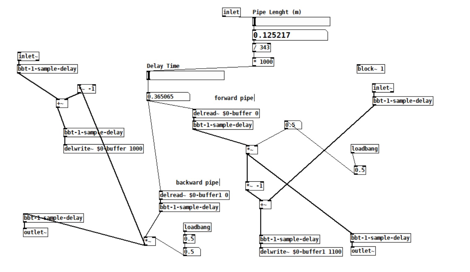
I tried all three.
Can you help me?
Cheers and Thanks
Polle
 posted in technical issues
Math detail problem of numbers larger than six or so decimals
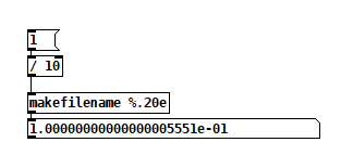
@raynovich I agree with your larger point. I don't understand why there isn't more interest in double precision floats. Single precision floating point only gives you so many digits--I think just one or two digits past where Pd is truncating. You can get control of those digits using ugly tricks like this:
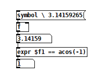
The backslash-escaped space before the pi digits stops Pd from truncating it.
 posted in technical issues
Large number representation in pd
@60hz double precision would solve the bit-depth issue, but the textual representation of numbers (floats) would also have to be changed to add precision. (I haven't checked if pd-double does this or not.. katja's page makes it seem like it does though)
here is her description from https://www.katjaas.nl/doubleprecision/doubleprecision.html :
You have probably noticed that single precision floats are represented in Pd with a maximum of 6 significant digits. This is done to hide inconsistencies like 33 * 0.3 = 9.900001, which happens when 7 decimal digits are shown. The limitation to 6 significant digits is however very annoying when we want to type or see large integers, like indexes of long audio buffers.
In calculations, Pd can use all integers from 0 to 2^24 = 16,777,216, over 16 million. Numbers with up to 8 decimal digits. But in the GUI, 1 million is shown in scientific notation as 1e+06. This scientific notation also uses a maximum of 6 significant digits. Therefore, the next representable number is 1.00001e+06, that is 1 million and 10. See below how the result of 2^20 is rounded in the GUI, as an example. The fact that numbers are also stored with patches this way, makes things worse. At 44100 Hz samplerate, one million samples is about 23 seconds - not at all that much. Longer audio buffers are allowed, but handling them in the GUI becomes tricky.
 posted in technical issues