20 mode pole mixing and morphing filter. Updated
@oid said:
I am referring to it being made up from multiple objects instead of just one, analogy between transistors and integrated circuits.
Ok well, I was refering to the inherent phase shift that any digital filter has because of the discrete time and delay. No biggie.
Probably not control vs signal domain since they both have [mtof] on the cutoff so should be set to the exact same frequency. I am not talking about cancellation during the morph, as I said some transitions don't work, a resonance morph from 24db hp to 12db lp works but 24db hp to 18db lp results in the resonance results in the wrong phase after the morph, but a morph from 12db lp to 18db lp works just fine (don't recall if those actual transitions are the troublesome ones, just a random example). I suspect an error that can only be seen on the text level, order of operations (don't see anywhere this could be the issue) or an actual error which can not be seen in the patcher like the duplicate patch cable bug. I am fairly certain this just recently cropped up and the non-[lop~] filters did work but that might have just been an illusion caused by the mysterious 10 sample delay which had cropped up some how, I have no idea, hence starting over from scratch come weekend.
For resonance to work, there has to be a full 360 degree shift of the cut-off frequency while the other frequencies get cancelled/phased out. This works when you have 4 1 pole filters doing 45 degrees shift on the cutoff frequency each and then do negative (180 degree shift) feedback. But when you start mixing the different poles for the feedback you get all sorts of different phase distortions that wont create the magic self oscillation we love so much. Maybe try using the [filter-graph] abstractions from H10.measurement.pd to measure phase distortion on your resonance pole-mix and see what is going on.
As an aside, know of any suitable externals which is essentially [lop~] with signal rate? I looked some but only found more complex filters, would be nice to have that CPU savings which [lop~] provides but keep signal rate inputs. Or is the CPU difference primarily the signal rate cutoff? Seems too great to be just that.
I just ran a test on [rpole~] vs [lop~] (seppareately!)
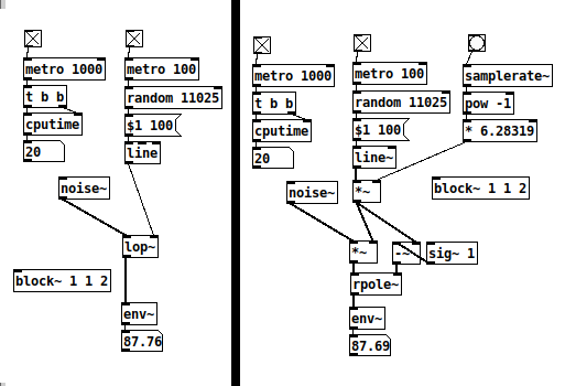
Setting [rpole~] up like here, it works 'exactly* like [lop~]. They both spike at 30 CPU but stay at 20 most of the time. I think [rpole~] is as cheap as it gets with signal rate cut-off control. Of course, small differences add up when you have several instances.
 posted in abstract~
"Couldn't create" when opening Help for all Cyclone objects
@plusch The usual folder structure in windows is a top folder called Pd.
If installed it will be in the Program Files or Program Files (x86) folder.
The contents look like this........
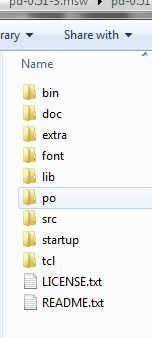
The bin folder contains the Pd executables Pd.exe and Pd.com
Usually Pd.exe is the program started when a patch is opened.
Anything in the bin folder will be found by Pd when it starts.
The wish program is in there...... it does the heavy lifting..... the console window and calls all the GUI stuff that is in the tcl folder.
Pd also knows to look in the doc folder as all the help files for vanilla objects are in its sub-folder "5.reference".
Pd also looks in the "extra" folder for externals.
But only as they are created.
Once it has found an object it remembers (until it is shut down) and doesn't need to search again.
So most libraries in the extra folder (and their help files) will work straight away.
But not single binaries...... some libraries just have a single binary that contains all its objects.
The problem is that an object in a single binary cannot be found by its name........ for example pix_video does not exist as a binary.......... it is wrapped up in the Gem binary.
A command........ -lib Gem...... must be added to the Pd startup preferences "Startup Flags" box.
The Gem single binary is then loaded as Pd starts and it has then already found all the objects.
If you install libraries elsewhere Pd cannot find them unless the whole path to the library is added to Pd Path Preferences.
And if it is a single binary that is also true....... and it will also need the -lib flag and to be added to the flags.
Although this behaviour causes a lot of "cannot create" problems when libraries are not installed to the extra folder it is useful as mentioned above when you don't want Pd to find an external....... or more especially you want to limit where Pd looks for objects so that it does not find other abstractions with the same name.
It also allows you to run many different releases of Pd without them interfering with each other if you don't actually "install" them....... but just put them in a folder somewhere.
BUT....... the Pd path and startup preferences are stored in the registry........ separately for 32 and 64 bit flavours. So all 64-bit versions will share their preferences settings (and 32-bit theirs).
The way around that is to start Pd from a batch file that specifies paths and flags...... then each release can be completely separated.
Batch files can also specify the other Pd command line flags....... so you can also set up different soundcards for example specifically for each Pd.exe.
David.
 posted in technical issues
Logarithmic glissando
One of the very early lessons that I teach in my interactive multimedia class is range mapping, where I derive the formulas and then leave them with ready-to-use patch structures for them.
-
If it's based on incoming data, first normalize (0 to 1, or -1 to +1, range). If you're generating a control signal, generate a normal range (e.g. [phasor~] is already 0 to 1).
-
For both linear and exponential mapping, there's a low value
loand a high valuehi. (Or, if the normalized range is bipolar -1 to +1, a center value instead oflo.) -
The "width" of the range is: linear
hi - lo, exponentialhi / lo. -
Apply the width to the control signal by: linear, multiplying (
(hi - lo) * signal); exponential, raising to the power of the control signal =(hi / lo) ** signal. -
Then (linear) add the lo or center; (exponential) multiply by the lo or center.
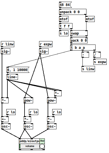
One way to remember this is that the exponential formula "promotes" operators to the "next level up": + --> *, - --> /, * --> power-of (and / --> log, but that would only be needed for normalizing arbitrary exponential data from an external source). So if you know the linear formula and the operator-promotion rule, then you have everything.
- linear: (width * signal) + lo
- exponential: (width ** signal) * lo
(Then the "super-exponential" that bocanegra was hypothesizing would exponentiate twice: ((width ** signal) ** signal) * lo = (width ** (signal * signal)) * lo.)
[mtof~] is a great shortcut, of course, but -- I drill this pretty hard with my students because if you understand this, then you can map any values onto any range, not only MIDI note numbers. IMO this is basic vocabulary -- you'll get much further with, say, western music theory if you know what is a major triad, and you can go much further with electronic music programming if you learn how to map numeric ranges.
hjh
 posted in technical issues
How much is a signal aliasing?
thank you, will study this, could you please add the missing
clone oddHarmonic~ 25
... couldn't create
@jameslo said:
what does it mean to low pass filter a signal at Nyquist, since the filter itself is subject to the Nyquist limit? Or maybe you have other reasons to do so?
Yes, that was wrong, I made many mistakes in that patch.
I'm still not convinced that comparing a signal with its upsampled version is meaningful. How do we know that the upper harmonics in the upsampled version are present and aliasing at the normal sample rate?
I see your point and I am not sure.
If this is the case, that whole concept would plop.
for measurement I wonder whether we should be instead passing the normal signal to an upsampled subpatch and then measuring how much energy is above 22050. Then again, that signal would look like a stepped signal in the upsampled environment, and that seems like it would have a lot of additional high frequency energy
No, I don't think so, as niquist reflects before upsampling. Even when using some upsampling filter, as in [inlet~]'s help, you can't un-alias an aliasing signal by upsampling !?
maybe you should try fft-split~
Yes, I was thinking about some steep FFT-filter,
https://forum.pdpatchrepo.info/topic/12245/perfect-filter-square-shape-filter
but don't know how to tweak it for different sample rates and with fairly precise cuttoff frequency, yet.
Bessel was not a good idea, high order Butterwoth is stronger, and everything needs to get calibrated, because the filter-slopes are messing with the result.
 posted in technical issues
How much is a signal aliasing?
@lacuna Thanks, that's really interesting. I don't think I solved this using FFTs because I didn't understand how to add the bins to get a meaningful measure of signal strength (among many other things). Looking over the code I wrote I can see it's gonna take a while before I understand what I was trying to do, but in the meantime maybe we can discuss your test and possibly poke holes in my original assumptions.
In my limited experience the filters in Pd do strange things when set to frequencies outside of the musical pitch range, so I would wonder if lp10_bess~ works properly at Nyquist. But I really don't know either way. And what does it mean to low pass filter a signal at Nyquist, since the filter itself is subject to the Nyquist limit? Or maybe you have other reasons to do so?
I'm still not convinced that comparing a signal with its upsampled version is meaningful. How do we know that the upper harmonics in the upsampled version are present and aliasing at the normal sample rate? My understanding is that upsampling just gives us more frequency headroom in which to filter out frequencies above Nyquist. But for measurement I wonder whether we should be instead passing the normal signal to an upsampled subpatch and then measuring how much energy is above 22050. Then again, that signal would look like a stepped signal in the upsampled environment, and that seems like it would have a lot of additional high frequency energy, so maybe that's a terrible idea.
I'm obviously more confused now than when I originally asked the question.
That said, I can't believe that there is an audible aliasing problem with plain sine waves. If you want I'd be happy to write you a double-blind listening test based on the Lady Tasting Tea experiment. Let me know and we'll work out what it should contain.
But assuming your method is valid, maybe you should try fft-split~ from Audiolab instead of the IEM filters. If I can understand my old code then maybe I'll have something more constructive to contribute later.
 posted in technical issues
Mono / stereo detection
aha, so they take messages when you name them? ")
[quote]What would not work is to patch a control and a signal in simultaneously: the signal will overwrite the control.[/quote]
haha, in max it is like that:
most externals take signals and messages at the signal inlets.
if you connect a signal and a number to math objects like +~, the number would multiply the signal value.
if you want to connect signals and messages to an abstraction, you have to use something like [route start stop int float] inside the abstraction - the signal will come out of the "does not match" output of [route].
to complete the magic, you can pack signals into named connections using [prepend stereoL] [prepend stereoR] [prepend modulation1] [prepend modulation2] and then you can send all 4 signals through one connection into the subpatch.
you can also mix different types of connections that way.
...
regarding the problem of the OP:
in max i made myself abstractions to enhance the function of inlets and outlets, where you can send a [metro 3000] into using s/r in order to find out which inlets are connected and which not.
in theory one could do that with audio, too, and add a pulsetrain of + 1000. to a stream, later decode the stuff by modulo 1000.
 posted in technical issues
Paths and organizing .pd files for use.
@raynovich I use the [declare] object instead of paths, keeps the paths list shorter and more manageable and also gives you a nice list of dependencies right in the patch so you never have to wade through the patch trying to figure out what it needs if you want to share the patch or copy it to a different machine. If you need a sub-folder you just declare the sub-folder. Use absolute paths when you declare, this way you can move the patch and it will still find what it needs. I generally have a sub-patch in each patch for declares and I avoid declaring folders, just declare the abstraction directly so I never have to try and figure out which abstractions a given patch uses, just open the declare sub-patch and it is all there. In my pd folder I have all my current patches, an abstractions folder, a folder for patches I am not currently working on and a folder for reference patches. I do my best to avoid making abstractions which only have use in a single patch, I will figure out how to generalize it to make it more useful for other patches so it can live in my abstraction folder without cluttering it up and helps avoid needing folders for patches. When a patch must have a folder it goes in the pd directory with the patch and I declare it instead of keeping the patch in it's own directory, this is mainly to minimize having to navigate folders as much.
Using [declare] to explicitly declare individual abstractions also makes it easier to clean your abstraction folder, a simple shell script can check for abstractions which are not used by any patch or ones that just get used by a single patch so you can check them out to see if they are worth keeping or should be moved too the folder of that one patch which uses them.
 posted in technical issues
Per-sample processing? (for Karplus-Strong)
@jameslo a lop in the feedback path is something I tried but I only found it useful to shape the spectrum rather than smooth out the signal to the dac. I ended up with some crazy sets of filters and it's great fun. When I do key-tracked lops I like to put the cutoff either right on the fundamental or maybe at 2x, 3x, depending on how steep the rolloff is. Thanks for the pointer, I'll have a look!
@Booberg Yes, that occurred to me and in effect I'm doing more or less that. Filtering the feedback chain like @jameslo says is also useful in containing unstable signals. However, in this case I'm not dealing with an unstable signal per se. I think the problem really is that the excitation signal has too harsh of an attack and the delay being too long makes the repeats noticeable as almost-separate events. A partial solution at this point is to either smooth the attack of the exciter or low-pass the output signal.
In general, though, I was wondering how using [gen~ ] manages to smooth things out without requiring filtering, and it seems the sample-level processing (as opposed to block-level) has something to do with it.
 posted in technical issues
looking for velvet noise generator
@porres oh yeah I always forget about [expr~] for some reason.. maybe bc of the license it used to have.
There's no real reason to have the phase reset inlet, just more control.
From what I can tell, velvet noise is outputting a 1-sample impulse of value that's either 1 or -1, chosen randomly, at a random point in a regular period.
So I have a [phasor~] to keep track of the period, and the [samphold~] samples a random value from 0-1 when the [phasor~] resets. This will be the point in the phase of that period that the impulse will occur. When the [phasor~] gets to above or equal to this value, the [<~ ] will go from 1 to 0. That goes into [rzero~ 1], which will put out a -1 on the sample that occurs. That goes into the [==~ -1], which acts (together with [*~ ]) as a gate for the noise value that has been manipulated to either be 1 or -1, depending on if the output of [noise~] is positive or not.
The issue with this original implementation was that when the [phasor~] wraps around to start a new phase, it can wrap to a value greater than the new [samphold~] value from the noise. That means that if the noise value is very small, there will be no impulse for that period since the [phasor~] value will never be less than the sampled noise value for that period (and therefore the [<~ ] won't go from 1 to 0, which means the [rzero~ 1] below it won't output a -1, and so on). So, the [rzero~] and [<~ 0] put out a 1-sample value of 1 when the [phasor~] wraps around, which is combined with the other signal in [min~ 1] to take care of this. That way the [rzero~ 1] below the [min~ 1] will get a 1 even if the wrapped-around [phasor~] value is less than the new sampled noise value, and there will be an impulse for that period.
(that is what "make sure there is at least 1 1 on wraparound" means)
edit: after writing all of this it occurred to me that the sampled noise value could also be greater than the value that the [phasor~] will get to before it wraps around.. perhaps the solution is to constrain the sampled noise value depending on the frequency and phase of the [phasor~]...
 posted in technical issues
"Nested instances" for distributing CPU load
Hello! First time poster here.
I'm looking in to the possibilities with sending signals between instances of PD.
My 'dream' scenario would be to have a setup something like this:
One "control" branch which handles most interaction with the real world, presets, signal routing and conditioning, etc. this would optimally be running at 96k (0.5x192k) sample rate.
One "sound generation" branch. Basically oscillators and some sound shaping, running 192k.
One "filtering and output" branch, running at 192k but with upsampling to 2x for the filter section. The "baseline" level of this branch would be hosting some envelope generators and the audio output.
So what I'm hoping for is to:
Send signals from both "real world" and the "control" branch, directly into "sound generation" and "filtering and output" in parallel. Having them arrive simultaneously at each destination.
This, while the audio would be running in a straight series manor:
Generation->Filtering->Output. (Hopefully not landing in the 192k level of the filtering branch before being upsampled and filtered..)
So...
Would this be possible? Maybe its just as simple as using sends and throws? Or are we forced to build in levels, so to say? Having control signals go through "Sound Generation" before heading on to "Filtering and output".
The documentation in how this feature works seems like a well kept secret I'm trying to find examples how others handle these things but I've been coming up short.
A bonus question, simple yes or no
Is communicating either control or audio, through the PD~ object, faster than the other?
I hope I spark some inspiration in someone who might put my spinning head to rest! I'm looking forwards to sharing this project when it's done, I think i've managed to get a very pleasing sound. The main reason for the layout I'm pondering is basically to have "note" and "velocity" sent directly to both "sound generation" and "filtering and outout", to minimize latency between keydown and envelope trigger. Maybe I'm just being stupid 
Cheers!
 posted in technical issues