[small job offer] porting max external to pd
Edit 1: Took a shot porting it in this little textarea. Probably doesn't compile yet...
Edit 2: Ok, this should compile now. I haven't actually tried to instantiate it yet, though. It's possible I set it up with the wrong number of xlets.
Edit 3: Seems to instantiate ok. It appears it doesn't take signal input so the CLASS_MAINSIGNALIN macro is neccessary. Just comment that part out to make it a control signal.
Note-- in my port it's called [vb_fourses~] for the reason noted below.
I have no idea if the algorithm behaves correctly, but it does output sound.
Btw-- AFAICT you should be able to compile this external for the 64-bit version of Purr Data and it should work properly. It doesn't require a special 64-bit codepath in Pd so I commented that part out.
Btw 2-- there should probably be a "best practices" rule that states you can only name your class something that is a legal C function name. Because this class doesn't follow that practice I made a mistake in the port. Further, the user will make a mistake because I had to change the class name. If I had instead made the setup function a different name than the creator I would create an additional problem that would force users to declare the lib before using it. Bad all around, and not worth whatever benefit there is to naming a class "foo.bar" instead of "foo_bar"
/*
#include "ext.h"
#include "ext_obex.h"
#include "z_dsp.h"
#include "ext_common.h"
*/

#include "m_pd.h"
#include "math.h"

/*
    a chaotic oscillator network
    based on descriptions of the 'fourses system' by ciat-lonbarde
    www.ciat-lonbarde.net

    07.april 2013, volker b?hm
*/

#define NUMFOURSES 4

static void *myObj_class;

typedef struct {
    // this is a horse... basically a ramp generator
    double      val;
    double      inc;
    double      dec;
    double      adder;
    double      incy, incym1;       // used for smoothing
    double      decy, decym1;       // used for smoothing
} t_horse;

typedef struct {
    t_object    x_obj;
    double      r_sr;
    t_horse     fourses[NUMFOURSES+2];  // four horses make a fourse...
    double      smoother;
    t_sample x_f;
} t_myObj;


// absolute limits
static void myObj_hilim(t_myObj *x, t_floatarg input);
static void myObj_lolim(t_myObj *x, t_floatarg input);

// up and down freqs for all oscillators
static void myObj_upfreq(t_myObj *x, t_floatarg freq1, t_floatarg freq2, t_floatarg freq3, t_floatarg freq4);
static void myObj_downfreq(t_myObj *x, t_floatarg freq1, t_floatarg freq2, t_floatarg freq3, t_floatarg freq4);

static void myObj_smooth(t_myObj *x, t_floatarg input);
static void myObj_info(t_myObj *x);

// DSP methods
static void myObj_dsp(t_myObj *x, t_signal **sp);
static t_int *myObj_perform(t_int *w);
//void myObj_dsp64(t_myObj *x, t_object *dsp64, short *count, double samplerate,
//               long maxvectorsize, long flags);
//void myObj_perform64(t_myObj *x, t_object *dsp64, double **ins, long numins,
//                     double **outs, long numouts, long sampleframes, long flags, void *userparam);
//

static void *myObj_new( t_symbol *s, int argc, t_atom *argv);
//void myObj_assist(t_myObj *x, void *b, long m, long a, char *s);


void vb_fourses_tilde_setup(void) {
    t_class *c;
    myObj_class = class_new(gensym("vb_fourses~"), (t_newmethod)myObj_new, 0, sizeof(t_myObj),
                  0, A_GIMME, NULL);
    c = myObj_class;
    class_addmethod(c, (t_method)myObj_dsp, gensym("dsp"), A_CANT, 0);
//  class_addmethod(c, (t_method)myObj_dsp64, gensym("dsp64"), A_CANT, 0);
    class_addmethod(c, (t_method)myObj_smooth, gensym("smooth"), A_FLOAT, 0);
    class_addmethod(c, (t_method)myObj_hilim, gensym("hilim"), A_FLOAT, 0);
    class_addmethod(c, (t_method)myObj_lolim, gensym("lolim"), A_FLOAT, 0);
    class_addmethod(c, (t_method)myObj_upfreq, gensym("upfreq"), A_FLOAT, A_FLOAT, A_FLOAT, A_FLOAT, 0);
    class_addmethod(c, (t_method)myObj_downfreq, gensym("downfreq"), A_FLOAT, A_FLOAT, A_FLOAT, A_FLOAT, 0);

    class_addmethod(c, (t_method)myObj_info, gensym("info"), 0);
    //class_addmethod(c, (t_method)myObj_assist, "assist", A_CANT,0);
    CLASS_MAINSIGNALIN(myObj_class, t_myObj, x_f);
//  class_dspinit(c);
//  class_register(CLASS_BOX, c);

    post("vb_fourses~ by volker b?hm\n");

//  return 0;
}


static void myObj_smooth(t_myObj *x, t_floatarg input) {
//  input = CLAMP(input, 0., 1.);
   if (input < 0.) input = 0;
     if (input > 1.) input = 1;
    x->smoother = 0.01 - pow(input,0.2)*0.01;
}

static void myObj_hilim(t_myObj *x, t_floatarg input) {
    x->fourses[0].val = input;      // store global high limit in fourses[0]
}
static void myObj_lolim(t_myObj *x, t_floatarg input) {
    x->fourses[5].val = input;      // store global low limit in fourses[5]
}

static void myObj_upfreq(t_myObj *x, t_floatarg freq1, t_floatarg freq2, t_floatarg freq3, t_floatarg freq4) {
    x->fourses[1].inc = fabs(freq1)*4*x->r_sr;
    x->fourses[2].inc = fabs(freq2)*4*x->r_sr;
    x->fourses[3].inc = fabs(freq3)*4*x->r_sr;
    x->fourses[4].inc = fabs(freq4)*4*x->r_sr;
}

static void myObj_downfreq(t_myObj *x, t_floatarg freq1, t_floatarg freq2, t_floatarg freq3, t_floatarg freq4) {
    x->fourses[1].dec = fabs(freq1)*-4*x->r_sr;
    x->fourses[2].dec = fabs(freq2)*-4*x->r_sr;
    x->fourses[3].dec = fabs(freq3)*-4*x->r_sr;
    x->fourses[4].dec = fabs(freq4)*-4*x->r_sr;
}


//#pragma mark 64bit dsp-loop ------------------

//void myObj_dsp64(t_myObj *x, t_object *dsp64, short *count, double samplerate,
//               long maxvectorsize, long flags) {
//  object_method(dsp64, gensym("dsp_add64"), x, myObj_perform64, 0, NULL);
//
//  if(samplerate<=0) x->r_sr = 1.0/44100.0;
//  else x->r_sr = 1.0/samplerate;
//
//
//}

//static void myObj_perform64(t_myObj *x, t_object *dsp64, double **ins, long numins,
//                     double **outs, long numouts, long sampleframes, long flags, void *userparam){
//
//  t_double **output = outs;
//  int vs = sampleframes;
//  t_horse *fourses = x->fourses;
//  double val, c, hilim, lolim;
//  int i, n;
//
//  if (x->x_obj.z_disabled)
//      return;
//
//  c = x->smoother;
//  hilim = fourses[0].val;
//  lolim = fourses[5].val;
//
//  for(i=0; i<vs; i++)
//   {
//      for(n=1; n<=NUMFOURSES; n++) {
//          // smoother
//          fourses[n].incy = fourses[n].inc*c + fourses[n].incym1*(1-c);
//          fourses[n].incym1 = fourses[n].incy;
//
//          fourses[n].decy = fourses[n].dec*c + fourses[n].decym1*(1-c);
//          fourses[n].decym1 = fourses[n].decy;
//
//          val = fourses[n].val;
//          val += fourses[n].adder;
//
//          if(val <= fourses[n+1].val || val <= lolim ) {
//              fourses[n].adder = fourses[n].incy;
//          }
//          else if( val >= fourses[n-1].val || val >= hilim ) {
//              fourses[n].adder = fourses[n].decy;
//          }
//
//          output[n-1][i] = val;
//
//          fourses[n].val = val;
//      }
//   }
//
//  return;
//
//}

//#pragma mark 32bit dsp-loop ------------------

static void myObj_dsp(t_myObj *x, t_signal **sp)
{
    dsp_add(myObj_perform, 6, x, sp[0]->s_vec, sp[1]->s_vec, sp[2]->s_vec, sp[3]->s_vec, sp[0]->s_n);

    if(sp[0]->s_sr<=0)
        x->r_sr = 1.0/44100.0;
    else x->r_sr = 1.0/sp[0]->s_sr;
}


static t_int *myObj_perform(t_int *w)
{
    t_myObj *x = (t_myObj*)(w[1]);
    t_float *out1 = (float *)(w[2]);
    t_float *out2 = (float *)(w[3]);
    t_float *out3 = (float *)(w[4]);
    t_float *out4 = (float *)(w[5]);
    int vs = (int)(w[6]);

// Hm... not sure about this member. I don't think we can disable individual
// objects in Pd...
//    if (x->x_obj.z_disabled)
//        goto out;

    t_horse *fourses = x->fourses;
    double val, c, hilim, lolim;
    int i, n;

    c = x->smoother;
    hilim = fourses[0].val;
    lolim = fourses[5].val;

    for(i=0; i<vs; i++)
     {
        for(n=1; n<=NUMFOURSES; n++) {
            // smoother
            fourses[n].incy = fourses[n].inc*c + fourses[n].incym1*(1-c);
            fourses[n].incym1 = fourses[n].incy;

            fourses[n].decy = fourses[n].dec*c + fourses[n].decym1*(1-c);
            fourses[n].decym1 = fourses[n].decy;

            val = fourses[n].val;
            val += fourses[n].adder;

            if(val <= fourses[n+1].val || val <= lolim ) {
                fourses[n].adder = fourses[n].incy;
            }
            else if( val >= fourses[n-1].val || val >= hilim ) {
                fourses[n].adder = fourses[n].decy;
            }

            fourses[n].val = val;
        }

        out1[i] = fourses[1].val;
        out2[i] = fourses[2].val;
        out3[i] = fourses[3].val;
        out4[i] = fourses[4].val;

     }
//out:
    return w+7;
}

static void myObj_info(t_myObj *x) {
    int i;
    // only fourses 1 to 4 are used
    post("----- fourses.info -------");
    for(i=1; i<=NUMFOURSES; i++) {
        post("fourses[%ld].val = %f", i, x->fourses[i].val);
        post("fourses[%ld].inc = %f", i, x->fourses[i].inc);
        post("fourses[%ld].dec = %f", i, x->fourses[i].dec);
        post("fourses[%ld].adder = %f", i, x->fourses[i].adder);
    }
    post("------ end -------");
}

void *myObj_new(t_symbol *s, int argc, t_atom *argv)
{
    t_myObj *x = (t_myObj *)pd_new(myObj_class);
//  dsp_setup((t_pxobject*)x, 0);
    outlet_new((t_object *)x, &s_signal);
    outlet_new((t_object *)x, &s_signal);
    outlet_new((t_object *)x, &s_signal);
    outlet_new((t_object *)x, &s_signal);

    x->r_sr = 1.0/sys_getsr();
    if(sys_getsr() <= 0)
        x->r_sr = 1.0/44100.f;

    int i;
    for(i=1; i<=NUMFOURSES; i++) {
        x->fourses[i].val = 0.;
        x->fourses[i].inc = 0.01;
        x->fourses[i].dec = -0.01;
        x->fourses[i].adder = x->fourses[i].inc;

    }
    x->fourses[0].val = 1.; // dummy 'horse' only used as high limit for fourses[1]
    x->fourses[5].val = -1.;    // dummy 'horse' only used as low limit for fourses[4]

    x->smoother = 0.01;

    return x;
}


//void myObj_assist(t_myObj *x, void *b, long m, long a, char *s) {
//  if (m==1) {
//      switch(a) {
//          case 0: sprintf (s,"message inlet"); break;
//      }
//  }
//  else {
//      switch(a) {
//          case 0: sprintf (s,"(signal) signal out osc1"); break;
//          case 1: sprintf(s, "(signal) signal out osc2"); break;
//          case 2: sprintf(s, "(signal) signal out osc3"); break;
//          case 3: sprintf(s, "(signal) signal out osc4"); break;
//      }
//
//  }
//}
 posted in technical issues
How do you guys organize your files?
@kullboys The only solution is to add paths to the "preferences... paths" of Pd.
And / or use [declare -path].
Obviously it can be useful to have a folder of projects, and each project within it can find itself easily......and its sub-folders with a [declare -path sub-folder] object in any patches that need it.
EG
projects (folder)
.... project_1 (folder)
......... main_patch.pd (contains [declare -path tracks -path data]
..........other.pd
..........tracks (folder)
..........data (folder)
If you then call that main_patch (adding it's folder to "prefs..paths"...... or using a [declare -path c:/...../project_1] in your new patch) then those sub-folders will be found as well.
When starting out, with few patches, this can be a bit annoying. But later, with thousands of patches and abstractions it will be an advantage. Your problem becomes excluding patches and audio that unfortunately have the same name, or plugins you don't want, or even versions of externals.... 32bit?....64bit?...... from other Pd versions that you have on your desktop.
Personally, I also have a folder on my desktop, with its path set in all my Vanilla Pd versions, into which I have put all the "extended" object "vanilla" replacements. That's another example of avoiding conflicts..
And then another desktop folder ( again, set in all prefs) into which I can temporarily dump copies for testing. I know that everything in that folder is a copy.
David.
 posted in Off topic
Pd-extended to Vanilla migrations issues. Gui freeze, console errors, etc.
Hello Dxk,
Yours are the exact instructions I tried to follow a few days ago.
As of now, I'm still a whole lot wiser. As far as I've understood, libraries that are contained in a single file are to be added to the "startup" for load at start-up. Libraries consisting of a folder with multiple, separate files should be added to "path".
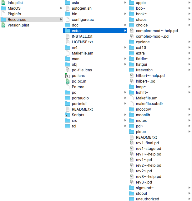
First off, the Deken manager downloads the libraries to a folder called "extra", not "pd-externals" or something similar. I've got no folder called that. I couldn't access the folder through the "choose folder"-prompt, since I have to access the contents of the Pure Data application, so I had to create a desktop shortcut to which I could easily choose the "extra"-folder when adding paths to "path".
This is what I am greeted with on start-up.
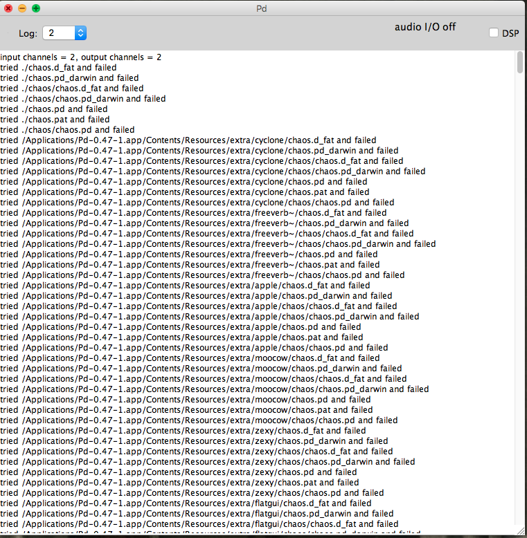
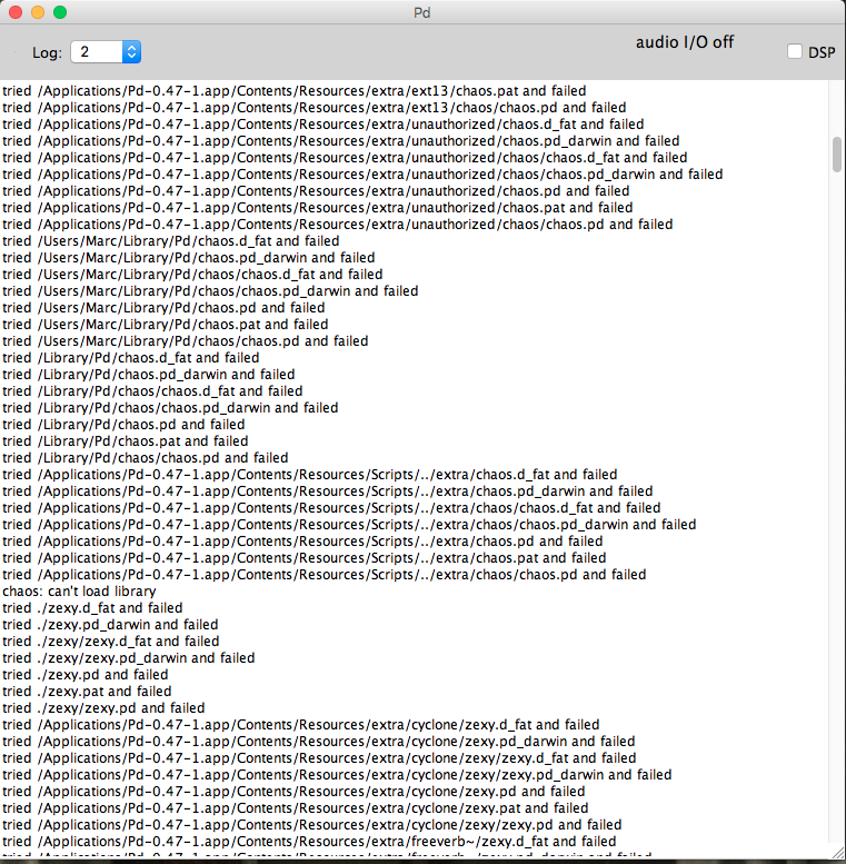
And it just keeps going all the way down. It seems to go through the contents of the libraries, but gives me a failed message. I now see that it looks for the contents of the zexy library in the folder of cyclone and tries to look for the files in neighbouring folders. Why would it do that?
But, say I call up an object I know only exists in an external library, say, cyclone's [cycle~] object, I will get this:
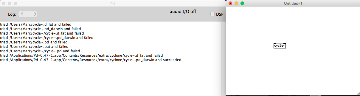
The first few lines show that it's trying to look for the library contents in my main folder (users/marc). I can't see why it would try that. It then tries the paths, fails, but then succeeds.
This is what my "startup" and "path" folders look like, respectively:
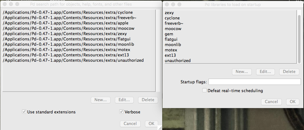
And the contents of the "extra" folder:
Thank you, in advance.
 posted in technical issues
What's your favorite noisegate?
@svanya Wow. Looks nice.
The values I had used for the various bands were chosen to approximate a flat frequency response. So, you adjusted one value, and the noise was suppresed (more or less) evenly accross all bands.
You've made it so that you can suppress the noise by band - sort of a graphic noise equalizer. ")
The value you've labeled hip_frq is what differentiates static noise from actual content. The lower this value, the longer a sound must be present for it to be removed as noise. Say, you sing a really long note that goes on for 10 seconds. If the hip_frq is set to 1Hz, then that note will be recognized as noise after a second or so and will be filtered out. So, you would set the hip_frq to a lower value (say, 0.1Hz) which will make the filter allow the long note. It also means that the filter will respond slowly to all noise. With hip_frq set to 0.1Hz, it will take around 10 seconds before a sound with a constant volume is filtered out.
The lop_frq is sort of the opposite. Anything whose volume changes to quickly is assumed to be noise. If lop_frq is set too low, then you will lose things like snaps or pops (say, the click of beating drumsticks together or the onset of a cymbal crash.)
The values for hip_frq and lop_frq I used were what I found useful for speech.
hip_frq probably needs to be lower for music, and lop_frq probably needs to be higher for music.
 posted in technical issues
Using sigmund to generate a noise sample then subtract it...
@svanya Hello Svanya...... first, I apologise for the "Spaghetti Omelette". Your patch was not at all messy. My damaged brain could not concentrate enough to comprehend any of it.
Noise is pretty random. There are elements of it that can be predictable depending on the source, but only by frequency. So a "hum" in Europe will be exactly 50Hz, and in the US 60Hz. High frequency noise (from poorer quality op amps) though is absolutely random. Often nowadays there can be some predictable noise from a computer bus, and again that can be filtered by a notch filter.
But apart from filtering those known frequencies you cannot "predict" the waveform of the noise. You can kill it dead with a reverse phase in real time, but once you have the desired signal, music or whatever, added to the noise then the battle is lost. You certainly cannot loop an "anti-phase" signal for future subtraction. The noise is not a repetitive waveform except for those determined frequencies.
Noise cancelling headphones have a microphone capturing the external noise and adding that out of phase to the headphone amplifier signal...... but the noise is "known" in real-time, which makes that possible.
As you have mentioned before, extreme filtering has some nasty side effects. In post production, where the "noise" is analysed, and an anti-phase signal added to what is deemed to be noise, the desired signal can be heavily distorted, to the point where some frequencies are so overly amplified that there is high frequency "ringing", and high frequencies "muted".... so the music ends up sounding like an old wax gramophone recording! It can only be used in very small doses. Clicks and pops are much easier to deal with.....
David.
posted in technical issues
What's your favorite noisegate?
@svanya Use the MultibandNoiseFilter. The left inlet is audio, the right sets how much noise to remove. The outlet is the filtered audio,
Attach a slider to the right inlet with a range from 0 to 2. That ought to be a wide enough range that you can adjust it to clean things up without also destroying the voice signal.
How it works is pretty simple, but difficult for me to put into words. If you are interested in how it works, take a look inside NoiseFilter and NoiseDetector.
NoiseFilter pretty much just attenuates the audio based on the noise level that it finds. How it finds the noise level is the trick.
It uses the subpatch dBr to find the level of the signal, then passes that through a highpass filter and a low pass filter. Those two determine what is seen as "static" noise. Anything that changes slower than the high pass is static noise. Anything that changes slower than the lowpass is signal. Anything that changes faster than the lowpass is noise.
Changing the value of the highpass determines how fast things get filtered out - if it "eats" your long notes, then you need to make the cutoff of the high pass lower.
Once it has the filtered level, it takes the absolute value of the variations in the level and compares them to the selected noise reduction level. Anything below the desired level closes the gate. Since this causes a pulsing signal, theres's a lowpass to smooth it out.
Now, you have a signal proportional to how much noise is in your signal. The more the noise, the lower this proportional signal is.
Multiply that with your original audio, and it attenuates the audio according to how much noise there is.
The rest is splitting it into bands so that you don't attenuate everything at once, but just the frequencies where there's noise.
posted in technical issues
Noise filter for microphone (Live Audio)
Well, the forum crash seems to have eaten my last post.
I have made a noise filter to clean up audio signals live.
Other noise removal filters need to have a noise sample selected and try to remove that noise from the complete track - they only work offline.
This patch works online. It removes any stationary noise from the signal and doesn't need any user adjustment except that it does need to be told how much to reduce the noise.
"Stationary noise" is a signal whose frequency content and amplitude stay (more or less) constant for over 1 second. Fan hum is a good example, as well as the more or less "white" noise from the wind from the fan. Car motor sounds from a car travelling at constant speed is also a good example.
It will also kill feedback squeal cold, even at the lowest settings.
The patch is built in layers, and the lower layers can be used independently or combined and used to build different filters.
The attached zip file includes all the components from the lowest level up to a complete demonstation that takes in audio from a microphone and puts out filtered audio on line out. It also includes a set of help files that describe the function and use of the various modules.
Included modules:
NoiseLevelDetector.pd - estimates the amplitude of the stationary noise
NoiseFilter.pd - attenuates the signal based on the amplitude from
NoiseLevelDetector.pd Since it is more effective at high frequencies, it is best to feed it limited bandwidth signals and use multiple filters to cover the desired audio range.
BandLimitedNoiseFilter.pd - a Noisefilter that only works on the specified frequency range.
MultibandNoiseFilter.pd - a complete filter that covers the range from 40Hz upto 22000 hz to filter the complete audio spectrum.
Test.pd - demo program that demonstrates the use of MultibandNoiseFilter.pd
It works best for speaking voices. Singing tends to be more stationary. It could be adapted to singing voices by changing a single value in one of the lower level blocks.
The original idea was to create filter for removing car noises from microphone audio for two-way radios. When used to cover just the range from 300Hz to 3000Hz, it does a very good job.
The biggest disadvantage is that it will start making "musical noise" if there is a lot of noise and the attenuation is set high. It also adds a slight echoing quality to the filtered audio.
The project is hosted on GitHub: PureData NoiseFilter project.
posted in patch~
DIY2 - Effects, Sample players, Synths and Sound Synthesis.
@unstable said:
Hey I got a question. in the compression patches I can kind of get my head around the amp factor section. But I don't get any of the att/rel section. Can anyone explain what that sgn~ (signum) is/does ? Secondly I can see the table is effected by the release but not really on the attack. I can hear the attack. The block size is 2. I'm guessing if the default block size is 64 samples then 2 means 128?? Or is it actually 2 ? This outputs a frequency between 0.019 and 57 into a VCF along withe the original amp factor. Any advice ?
ok, so the [amp-factor] stage is giving the amplitude of the signal, scaled according to our threshold and ratio settings. This will either be positive if the amplitude is rising, or negative if it's falling.
next we go into the [att-rel-filtering] section, where we separate the attacks (positive) from the releases (negative)
[block 2] really does mean that the blocksize is only 2 samples. This is so that the [tabsend~] and [tabreceive~] objects deal with packets of two samples at a time,
giving us a sample delay between the input signal and the signal received by [tabreceive~]. If the blocksize were the default of 64, then we would have a 64 sample delay, and our compressor would not work at all well.
sgn~ just gives the sign of the signal, so -1 for negative numbers and 1 for positive ones. note that we are dealing now with just the AMPLITUDE of the signal, which has been scaled in the [amp-factor] section so that rising amplitude (ie, attack) is positive and falling amplitude (release) is negative.
that is then split apart using [max~ 0] with attack sent to the left outlet and release sent to the right outlet. The attack and release stages are both scaled separately (attack scaled by 0.019 to 57, and release by, i think, 0.00019 to 5.7) (and i don't know exactly WHY 57 was chosen, i'm sure the patch would work just as well with 50 or 60)
then we go through the [vcf~]. Although vcf~ is normally used to shape the frequency content of a wavform, in this case, it has a different use. It is smoothing the amplitude signal. So, if we set a fast attack, then the vcf~ will have a cutoff of 57hz, and our compressor will attack within 20ms. if we set a slow attack, then the vcf~ will have a frequency of 0.019hz, and the compressor will take a few seconds to fully attack.
finally, the original signal is multiplied by the compression factor, and sent along its way.
There are some quick mods you can do to this patch, too. A sidechain compressor, essential for any sort of 'french' electro sound, can be made by adding another inlet~ for a second audio signal, and taking the inverse of the compression factor, like this:
[pd att-rel-filtering]
|
[-~ 1]
|
[*~ -1]
and then multiply your second signal by that.
also, it is fun to take the compression factor output to its own [outlet~] and use it as a modulation source for filter cutoffs for synth sounds, etc.
anyway, hope that clears things up a bit?
have fun!
 posted in patch~
Better sounding guitar distortion ... beyond \[clip~\] and \[tanh~\]
Hi there,
thank you for your feedback !
@mod said:
wow, nice to finally see this!
why are highs contrary to what you'd expect? at a low sample rate, the highs are folded back into low frequencies, but when you upsample, the highs are preserved as true highs. i think it works just how it should. The upsampled version is certainly much clearer and brighter to my ears. Particularly with a high distortion level.
That makes sense. The upsampling workaround officially wins (I'll try x16)! I think I focus too much on highs, as I tend to find this disto patch rather 'acid'; the original sample sounds much darker than the distorted sound. I don't owe the actual pedal so I only rely on my 'feeling', which is far from reliable ") Of course it's logical to add highs with such a nonlinearity, and lows are filtered several times.
Of course it's logical to add highs with such a nonlinearity, and lows are filtered several times.
Anyway I still find the heavily distorted sounds have a strong 'schh schh schh component' in the highs, and I can't remember having heard that as strong in actual analogic effects. Would you agree with that? Of course I know this is a rather basic 'physically-informed' design, and that analog will always sound better
@mod said:
actually, this patch really demonstrates the effect of aliasing. if you turn the tone knob down as far as it will go, and also turn the distortion down to zero, and turn aliasing off, you can clearly hear the rustling noise caused caused by those wrapping frequencies.
turn aliasing back on again, and the noise is gone.
Very strange, when I do what you say, the upsampled version sounds like the 'not upsampled one', with a 'sch sch' noise added !
@Maelstorm said:
@nau said:
The BJT gains are bound to my 'signal amplitude policy' : input file or audio source and output should never clip. These gains can be seen as follows : the first one (before the clipper) adjust 'how early' distortion occurs, and the second one gives the distorted signal a boost in order to give similar subjective level than dry signal.
The values were found empirically.This might be where I have the biggest issue, though the article doesn't make it so clear, either. [...] the DS-1 isn't a baby's distortion pedal.
[...] Also, you don't need to calculate the boost into the filter coefficients. That's only useful for plotting. You can just use [*~] before or after the filter do accomplish it.
I understand all these arguments. I'll modify the patch. At the beginning I was using this kind of reasoning, but as the 'nominal input level' is -20dbu (http://www.bossus.com/gear/productdetails.php?ProductId=127&ParentId=254#), and the dbu definition I found seemed difficult to bind to 'our' db, I just dared to make the basic (36db-20db=16db~6.3 times in amplitude) operation... not far from the 6 in my patch Not very scientific, though.
Anyway I understood another reason why my 'subjective hearing' failed: feedind my patch with a 0db normalised sample maximizes input level, and the result will always be 'over the top' compared to non-active guitar pickups with a volume knob not always pushed to max. In other words, if I look at demos on youtube the result heard will be less distorted than my patch's. Anyway this can always be seen as an additional parameter for a 'parametric DS1 deluxe edition patch'
@Maelstorm said:
As mod said, it's not so much more highs as less lows, and those lows are a result of aliasing. To my ears, the upsampled version sounds less muddy. (By the way, in your upsampled portion, you have a different argument for the second [DS1-bjt_stage~]. Making them equal makes the difference even less noticeable, and draws more attention to the mud than the highs.)
Ok, upsampling wins !
@Maelstorm said:
Yes, there is a difference, but it's not a Matlab thing. It's the choice of the logarithmic scaling in the x-axis. The article uses powers-of-ten as equal distances. Mine uses [mtof] for the scaling, so that a semitone, octave, or whatever musical interval is the same distance. Also, I made an adjustment so that everything between 0 and about 20 Hz (at 44.1k) gets squashed in the leftmost 10% of the graph. If I didn't to that, then about half the plot would be taken up with frequencies below the audible range.
Ok, perfect ! Everything's cool now.
@Maelstorm said:
(commenting peaking after ToneStage)
This has nothing to do with your tone stage. It's because of the passband ripple in the Chebychev filters. The IEM Chebychev filters have a 1 dB ripple, though I don't actually know if that means +/- 1 dB or +/- .5 dB. Either way, it's creating a boost at some frequencies, and pushing the output down by 1 dB should keep it below [-1, 1]. This could also be contributing to the highs, as the ripple is typically more pronounced near the cutoff frequency.
Mmh, I thought the same, but then I decided to check the plots taken out of the 'not upsampling' part, and the peaking is still there ! The Chebyshev filters can be the source, then ...
@Maelstorm said:
The output from [tanh~] will never clip, so as long as you make up for the ripple and don't boost the second BJT stage, you should be fine.
[...]
Just one more thing to add for now, and that is you're doing too much in the upsampled portion. The only thing that needs to be in there is the non-linear function ([tanh~]) and the anti-aliasing filters. Everything else is linear and doesn't benefit from upsampling, so it's just creating more computational load.
Of course I precisely want to get rid of this peaking to be able to fully rely on [tanh~] to 'master' my output gain. I'll try the FIR instead of cheby (as proposed by acreil) some day. (I don't even know yet how they work and how I'll have to implement it).
I left the 'full upsampled chain' in this patch only to see if someone would have commented it, and we totally agree. But this 'playing the noob' attitude of mine is a rather raw 'fishing method' for getting stimulating information ... sorry this lead you to lay down the whole picture BUT nothing wasted, as your final 'delicate' -1db cut surprises me and I'll use it (when I'll get rid of peaking) and moreover, as you are reminding me that you use a 18000 cutoff freq, I'll give a look again at it, just trying to find a good criterion to pick one
Thank you everybody,
See you,
Nau
P.S. : sorry for those very long sentences ... not very clear
 posted in technical issues
Better sounding guitar distortion ... beyond \[clip~\] and \[tanh~\]
Also quite glad to see this! This has become one of my favorite threads of the forum. It covers a lot of ground, and it's great to see your hard work and perseverance payoff here. Cheers too you, nau!
@nau said:
The BJT gains are bound to my 'signal amplitude policy' : input file or audio source and output should never clip. These gains can be seen as follows : the first one (before the clipper) adjust 'how early' distortion occurs, and the second one gives the distorted signal a boost in order to give similar subjective level than dry signal.
The values were found empirically.
This might be where I have the biggest issue, though the article doesn't make it so clear, either. In the article, it shows the frequency response of the BJT stage as having about a 36 dB boost in the pass band. That amounts to multiplying the signal by about 63. And, if you want to get really technical, the waveshaper in the article clips at +/- .6, so you'd have to add about another 4.5 dB to make up for that. You're using much lower values. This is what I was talking about earlier when I said you should really crank the input to [tanh~] to get some serious distortion, and the DS-1 isn't a baby's distortion pedal.
Now, the article also says that the second BJT stage is really to boost the signal back up for the subsequent load. Since we're not sending this into other circuits here, I think the dB boost of the second BJT should be ignored. Also, you don't need to calculate the boost into the filter coefficients. That's only useful for plotting. You can just use [*~] before or after the filter do accomplish it.
So basically what I'm saying is, there should be a boost of about 40 dB ([*~ 100]) as part of the first BJT stage, and no boost for the last one. Then you can really break some teeth with this distortion.
- when switching between upsampled or not upsampled processing, the difference is barely noticeable (maybe the upsampled one has more highs, but that is the exact contrary of what I would expect). Does someone see what I am doing wrong, if this is the cause of this perceptual draw ?
As mod said, it's not so much more highs as less lows, and those lows are a result of aliasing. To my ears, the upsampled version sounds less muddy. (By the way, in your upsampled portion, you have a different argument for the second [DS1-bjt_stage~]. Making them equal makes the difference even less noticeable, and draws more attention to the mud than the highs.)
- the transfer curves can be seen in the patches, but are always slightly different than the one showed in the article. But I have been very careful when calculating coefficients and I don't really think they are wrong. Would there persist a difference between [filterplot.mmb] and traditional Matlab-like graphs ?
Yes, there is a difference, but it's not a Matlab thing. It's the choice of the logarithmic scaling in the x-axis. The article uses powers-of-ten as equal distances. Mine uses [mtof] for the scaling, so that a semitone, octave, or whatever musical interval is the same distance. Also, I made an adjustment so that everything between 0 and about 20 Hz (at 44.1k) gets squashed in the leftmost 10% of the graph. If I didn't to that, then about half the plot would be taken up with frequencies below the audible range.
- The DS1-tone_stage helpfile has been written by Maelstorm, and the response curve shows no gain value above 0db. Nevertheless the tone knob, when pushed, can lead to signal amplitude beyond [-1 1]... I can't figure out how a signal can have all its discretised frequencies pulled down and still exhibit peaking. Should I read more about the subject (is there a name for this symptom ?), or is there an error in my patch ?
This has nothing to do with your tone stage. It's because of the passband ripple in the Chebychev filters. The IEM Chebychev filters have a 1 dB ripple, though I don't actually know if that means +/- 1 dB or +/- .5 dB. Either way, it's creating a boost at some frequencies, and pushing the output down by 1 dB should keep it below [-1, 1]. This could also be contributing to the highs, as the ripple is typically more pronounced near the cutoff frequency.
- is my 'signal policy' perfectible ? I want the output signal never to clip, so I multiply the output by 0.4 in such a way that when Tone and Dist are full right but Level is medium the signal never clips.
The output from [tanh~] will never clip, so as long as you make up for the ripple and don't boost the second BJT stage, you should be fine.
Just one more thing to add for now, and that is you're doing too much in the upsampled portion. The only thing that needs to be in there is the non-linear function ([tanh~]) and the anti-aliasing filters. Everything else is linear and doesn't benefit from upsampling, so it's just creating more computational load. So it should look more like this:
[*~ 100]
|
[DS1-bjt_stage~ 1]
|
[DS1-opamp_gain~]
|
[*~ 8]
|
[pd upsample]
|
[DS1-tone_stage~]
|
[DS1-bjt_stage~ 1]
|
[*~ .891] <-- 1 dB cut
And [pd upsample] should look like this:
[inlet~]
|
[lp10_cheb~ 18000] [block~ 64 1 8]
|
[tanh~]
|
[lp10_cheb~ 18000]
|
[outlet~]
Okay, that turned out to be more words than I expected. But we're getting into DETAILS here! Again, nice work, nau.
 posted in technical issues