Trying to add key switch functionality to a midi controller
My question about this:
-
Right hand first, then left hand: Note should be produced upon the left-hand note on.
- What if one right-hand note is pressed, and two or three left-hand keys? Multiple notes, or only the first? (Polyphony, I suppose, would have to be right-left, right-left, not the same as right-left-left.)
-
Left hand first, then right hand: Should it play the note upon receipt of the right hand note-on, with the left-hand velocity? Or not play anything? Or something else?
- And, if it should sound, what about left-right-right? Portamento? Ignore the second?
Because a full solution will be different depending on the answer to these questions. These need to be thought through anyway because you can't guarantee correct input -- the logic needs to handle sequences that are not ideal, too.
hjh
 posted in technical issues
How to loop/reset an audio file to the beginning
I'm not at the computer now, but I would proceed by steps.
Sensor = 1 play/resume, sensor 0 = stop. Get this very simple specification working first.
Then start the timer on sensor = 0 and be sure that the timer is counting correctly.
Btw I think you can simplify this using the pd [timer] object. Why? Because you need to know the elapsed time only when the sensor was 0 but becomes 1. So there is no need to poll the time continuously. Sensor 0, bang to timer's left inlet, sensor 1 to timer's right inlet.
Then:
- If the sensor goes to 0, the playback rate should change to 0 (pause).
- If the sensor goes to 1, the playback rate should change to 1 (play again).
- Note that these two behaviors do not depend on the timer at all!
- Then, also at the moment when the sensor becomes 1, if the timer shows a long enough period, then you would also send "all" to the left inlet.
hjh
posted in technical issues
How to loop/reset an audio file to the beginning
I will check it late on my mac computer. for the moment I'm not on my computer, so I don't want to waste much time on it now as I think it will work on my computer.
For the moment I'm using your help file patch which is great. Your abstraction is so much more easy to use then from my patch I shared in the beginning.
what I'm trying to do is the following -
I will have 8 different sound files. Each sound file should be in a individual sf-play2~ object.
I will have data from 8 diffrent sensors I'm reading via arduino. Each sensor will report 0 or 1 (if sensor is pressed or not) alongside with analog data of numbers between 0 - 1023.
What I would like to do is that when I'm reading 1 the audio file will play, when reading 0 the audio file will pause . if 1 is held and the audio file arrived to it ends it will continue from the beginning. (loop 1) . I will also have a clocker to report how much time has elpased since sensor is 0. If more then x seconds the audio file will go back to beginnnig so next time sensor is held (1) it will start from the beginnnig.
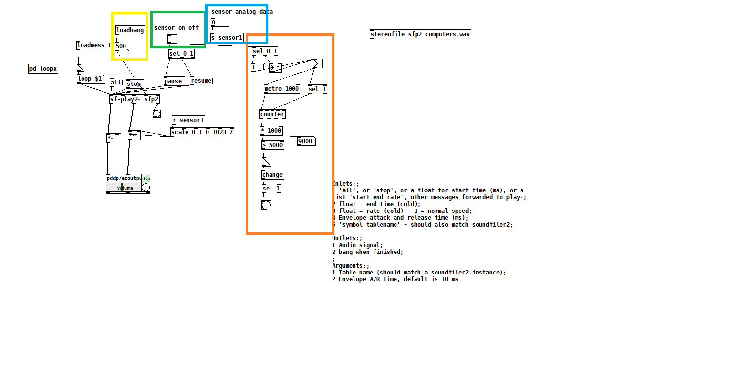
here is my try with your abstraction.
the green part is to imitate the on off from the sensor. the blue is the analog data from sensor.
the orange part is my try to make a clocker that will start count when sensor is off. The yellow part is for small envelop to avoide clicks when audio is pause and resume.
How can I make the audio file go to the beginning when the orange part is reporting a bang (that time was elapsed) ?
Also - I'm not sure if the yellow section is working. Meaning if it is indeed making an envelope on every pause and resume ? Is that possible?
Thanks!
edit: the scale of the sensor should be inverted. 0 1023 0 1
edit 2: how can I make the sf-play2~ go back to the beginning of the audio file without starting it immediately?
edit3: how can I load the file to the sf-play2~ object without starting it? if I don't press "all" message it won't load the file. I would lik the file to be loaded to the beginnnig, but to start and play only when receiving data from sensor on off. for the moment if I'm not pressing all message the file won't play.
 posted in technical issues
Arduino->Pd with Open Sound Control
@jameslo Thanks a lot!
I can send messages locally between Pd, Processing and Unity. But not Arduino.
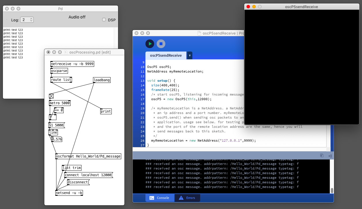
oscProcessing.pd
oscUnity.pd
oscP5sendReceive.pde
These works but I can still not for example replace Processing with Arduino.
@jameslo said in [Arduino->Pd with Open Sound Control] do you need bidirectional messaging? What data are you passing (if any)? What Arduino library would you prefer to use (I see there are more now than when I started)? is it over WiFi or ethernet or something else?
-bidirectional is good. Type of data, analog float, and digital. I have no preference for what library I use. I just want to make it work locally on a single computer.
I would like to use the Arduino as a controller for Pd through OSC.
For example, 5 analog ins on the Arduino that I after som treatment (smoothing and more) send locally to Pd, with custom osc addresses: /myArduino/analog-0
 posted in I/O hardware diy
Audio click occur when change start point and end point using |phasor~| and |tabread4~|
@Junzhe-hou said:
@ddw_music Hi professor!?!? good to see you here!

Yes, it's me -- I almost didn't notice your username 
I read your email last week but im so confused with your
patch--varispeed-segment:|noise~|
|
|lop~ 3|
|
|*~ 30|
|
|+~ 1|
This is just a way to generate a modulator for the playback rate. It could be any other modulator (LFO, envelope, anything).
After that, this is multiplied by a sample rate scaling factor.
As you asked jameslo: "if sample rate (in audio setting) changed the result sound different":
-
If the file sample rate is 96 kHz and the soundcard sample rate is 96 kHz, then normal-speed playback is to move forward exactly 1 sample in the file for every output sample.
-
If the file sample rate is 96 kHz and the soundcard sample rate is 48 KHz, then normal-speed playback is to move forward exactly 2 samples in the file for every output sample. (If you playback at 1:1, then the file will sound slower at the lower soundcard sample rate.)
This was one of the big reasons for me to make [soundfiler2] in my abstraction set. It calculates file_sr / system_sr and saves this in a value object named after the ID+"scale". If you multiply the playback rate by this scaling factor, then the file should sound correct at any system sample rate.
(BTW you would have the same issue in SuperCollider: PlayBuf.ar(1, bufnum, rate: 1) will sound different depending on the hardware sample rate, but PlayBuf.ar(1, bufnum, rate: BufRateScale.kr(bufnum)) would sound the same, except maybe for aliasing when downsampling.)
You method "L inlet = rate * scale for sample increment",so is the rate always changing?
Yes -- variable-speed playback.
@jameslo "I'm sorry if I just did your student's homework" -- actually this isn't for my class -- independent project. There are still some students who do hard things just because it's fun to overcome challenges 
hjh
posted in technical issues
List Comparison
@buzzelljason Yes. Well. Everything sent by a control rate object is a message.
The messages can be floats or symbols or lists.
Lists are a list comprising floats or symbols or a mixture of the two.
Items (atoms) in a list are separated by spaces.
It gets complicated.
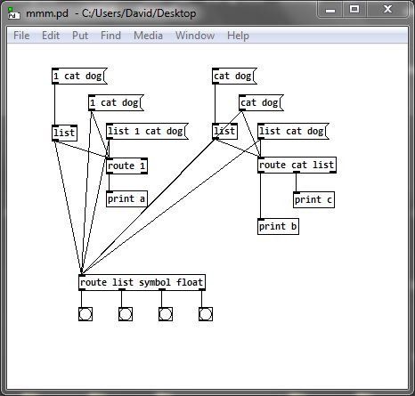
If the first atom in the list is a float then the "list" tag is automatically applied, and then is silently ignored and dropped as it passes through the next object (except for [route list symbol float].......)
If the first atom in the list is a symbol then that symbol becomes the tag.... the list header..... and the list can be routed by that tag. But if the list passes through a [list] object then "list" is added (prepended) as the header. That is why [list trim] is used almost everywhere after a [list] object...... to remove the header and then be able to [route] by the original tag (if it was a symbol).
HINT.. If you install the Zexy library then [rawprint] shows you whether an atom is a "tag", 'symbol' or float....
Trying to work with vanilla OSC objects can be just guesswork without [rawprint].
mmm.pd
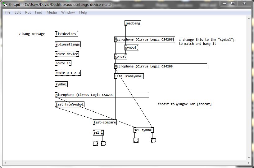
The messages arrive from [audiosettings] as a list which is a mixture of floats and symbols........ but the first atom is a symbol and there is no "list" tag.
[listdevices( returns a series of messages..... they are lists...... with the first atom "device"
That is why "device"....... a symbol.... and "0" or "1" can be routed. "1" could not be routed by [route 0 1] unless it is a float and "device" could not be routed by [route device] unless it is a symbol.
The device name is a symbol........ it can only be sent on in one hit because it is a symbol...... if it were a list then each part would be sent separately as a space normally "means" "next item".
But once it has passed through [route 0 1] it has lost its "symbol" tag. That can be put back by passing it through [symbol].
So the problem for [list-compare] is to create a symbol that is identical. Not easy as a message with component symbols will be treated as a list. Fortunately @ingox gave us a vanilla solution.... [concat].
And then of course to turn them both into lists for the comparison.
This will work........ this.zip
It can probably be simplified (and certainly @ingox will shortly post a more elegant solution....  ).
).
David.
 posted in technical issues
Control MIDI sampler rate from -2x to 2x with CC messages
Hello.
I need help implementing logic.
Let me explain :
I have a MIDI sampler and I would like to take control of the rate (speed/pitch) via MIDI CC messages.
The rate goes from -2x (reverse) to 2x (forward. It takes CC values from 0-127.
With a value of 64, the rate is at 0, so the sampler on pause, kind of
With a value of 127, the sampler plays forward 2x the original rate
With a value of 0, it plays reverse 2x the original rate
And with a value of 95, it plays forward at the original rate (1x)
Here’s what I’m trying to achieve :
I would like to be able to play with the rate and at some point, momentarily, thru a CC message, jump to the opposite side with the same rate ; for example, from 1x to -1x or from 0.5x to -0.5. I know that from 1x to -1x need the CC value 95 (1x) and 31 (-1x). I found that by subtracting 64 to the CC values received and I get the value that correspond to the reverse rate value of the sampler. But I get confused when I send values below 64, then I get negative values. It would be great if when I get under 64, then the logic would be reversed and I would get values over 64. I don’t know if my explanations are clear.
Thank a lot for you help.
Regards.
 posted in technical issues
Having lots of switches into Pd
Thank you for replying and sorry if I am unclear. I will try to slow down a bit.
@alexandros said:
@cfry definitely not necessary to use two Arduinos. I can't really understand where your problem lies.
-The problem is that it does not work when I try to use an arbitrary combination of pins in different modes (Digital in, Digital out, Analog in, Analog out).
Another problem is that I have a hard time reading the code parts that are handling the conversion data in order to do the serial communication, although I understand the principle of it.
You didn't reply to my earlier question about the pinMode calls where you use INPUT_PULLUP on analog inputs. Is this really necessary?
-I assumed that the problem lied in void ()loop as a conflict between the output and input handling sections. And that pinMode calls in void setup() was not relevant in this case. That is why I did not answer that question directly.
Also, why not use the analog pins in an array like with the digital pins? It will save a lot of writing and it's less error prone.
-I was foreseeing that I may want to configure those pins individually, but I can set it up with a loop for now.
One thing you might want to consider is having the Arduino notify Pd when it's done sending all its data and that it's ready to receive. That could be done at the end of the loop() function like this:
Serial.print("done ");
Serial.println("bang");
And in Pd have a [r done] object which will output a bang. Use this bang to send data from Pd to the Arduino by unpacking a list with all the accumulated data, possibly with a [list-abs/list-drip].
I use this notification technique in my 3dPdModular system, but there's a LOT of data there and it was only necessary. Perhaps you could try it out.
-I will try that.
Since I consider this to be basically your code I assumed that you could easily just insert the code for both input and output in void loop() in a way that works and that would show me how to solve it. Then I would be able to do further explorations and it would be end of story.
I will digest this a bit and may start a new thread, since this one has slided from "Having lots of switches into Pd" to "having a working code template for communicating between Arduino and Pd using and an arbitrary mixture of pin modes".
Please let me know if this still does not make sense. Thank you so much!
posted in I/O hardware diy
Shared references to stateful objects?
This is how i see it:
| ┏━ | ━━━━━━━━━━━━━━━━━━ | ┳━ | ━━━━━━━━━━━━━━━━━━━━━━━━━━━━━━━━ | ┓ |
|---|---|---|---|---|
| ┃ | Functional programming | ┃ | Pure Data | ┃ |
| ┡━ | ━━━━━━━━━━━━━━━━━━ | ╇━ | ━━━━━━━━━━━━━━━━━━━━━━━━━━━━━━━━ | ┩ |
| ├ | Function | ┼ | Abstraction | ┤ |
| ├─ | ────────────────── | ┼─ | ──────────────────────────────── | ┤ |
| ├ | Define function in code | ┼ | Create abstraction as separate file | ┤ |
| ├─ | ────────────────── | ┼─ | ──────────────────────────────── | ┤ |
| ├ | Call function | ┼ | Send a message to left inlet of the abstraction | ┤ |
| ├─ | ────────────────── | ┼─ | ──────────────────────────────── | ┤ |
| ├ | Arguments | ┼ | Input into the inlets and creation arguments | ┤ |
| ├─ | ────────────────── | ┼─ | ──────────────────────────────── | ┤ |
| ├ | Return values | ┼ | Output of the outlets | ┤ |
| ├─ | ────────────────── | ┼─ | ──────────────────────────────── | ┤ |
| ├ | Local variables | ┼ | $0 in object names | ┤ |
| ├─ | ────────────────── | ┼─ | ──────────────────────────────── | ┤ |
| ├ | Recursive function | ┼ | Manual recursion by using [until] outside of the abstraction | ┤ |
| └─ | ────────────────── | ┴─ | ──────────────────────────────── | ┘ |
 posted in technical issues
pduino for Vanilla or how to control arduino outputs from PD
[arduino] is the Pduino abstraction that communicates with Arduino via Firmata, and I think it's vanilla. Any way, if all you want is to control Arduino pins from Pd, you just need to send the correct bytes to Arduino through [comport].
I've written a tutorial on the communication between Pd and Arduino which you can find here, under "Tutorials", it's called "Arduino for Pd'ers".
After I wrote the tutorial I also wrote some abstractions to facilitate this communication, which are not used in the tutorial. You can get them here. Though, these are meant to receive data from the Arduino, not send. Sending data is covered in the tutorial.
 posted in technical issues