Pduino-based multi-arduino wireless personal midi controller network
I am trying to find out if and how to create an arduino fio/xbee based wireless network of multiple fio/xbee's? 4 to be exact.
I am currently building a wireless system consisting of 2 "hand units", a wireless mouth interface and a base station xbee interfacing with pure data. www.beatjazz.blogspot.com. i already have the first fio/xbee communicating with the base station and pure data using pduino and all is perfect. this weekend i pick up the other 2 arduinos and fio's. all 3 arduinos need to connect with the pure data at the same time.
the instrument i am building is a wind midi controller except that instead of it being one horn like instrument, allthe left hand keys are in a wireless unit attached to the left hand and same goes for the right hand. the mouthpiece is worn like a headset microphone and is a pressure transducer for breath and a FSR for lip pressure. they must all work together as if one instrument. most of the coding has been done, andnow is time to split that code to the multiple wireless nodes.
it would seem that since all the xbee's have their own id's that that would translate over to the arduinos they are connected with and the whole network should come into the computer thru one serial port, which should solve that problem. I am wondering; how i might interface the 3 arduinos to pure data/pduino? theoretically, shouldnt i be able to name instances of the [arduino] object, say [arduino left], [arduino right], and [arduino mouth] so that each fio has its own instance? if so, how do i recognize the individual fio's and make use of their individual id's if that is the case at all?
Thank you in advance for any insight anyone might share.
Onyx
 posted in I/O hardware diy
Constructing midi messages from sensor data
I’m just reading you project idea.
To read a value of a sensor (mic for example) with a PIC (or Arduino)you have to read this data using an analogue input of the PIC (Arduino).
A PIC can understand values DC between 0 and 5V. An outgoing signal of a mic (it has to be preamplified)is a AC signal and can’t be interpreted by a PIC (or at least you get only some random results).
To make a readable signal for a PIC from a mic (or pressure sensor) you need to use an envelope follower.
The Arduino has 8 analogue-inputs with a 10bit resolution, 4,7mV.
Now to send this bites wireless you have to create some protocol with (8bit) bytes to tell Pd the how to interpret the incoming data flow.
In my project I send 3 bytes to Pd. The first byte is a 0X00 value to initiate a switch, the second byte is “result_hi-byte” and the third byte “result_lo-byte” of the PIC.
If the value of the analogue input trops to 0x00 (no mic pressure) a last byte with a number of the input channel is sent to Pd. In this way I can define the duration of a Note, very similar to a Note-Off message of a midi_message.
I made a program for Pd and if you want I send it to you.
To send a value of a button is much easier. A button has only the value On/Off, Yes/No, so with one byte you can define the value of 8 buttons.
In my webpage I have information about envelope followers and other things. www.drumanart.com
saludos Martin
 posted in technical issues
Animata / eyesweb / MAC
Hi kinolab, here interesting news for you:
As a gift for the beginning of 2011, there's a new "unstable" version
of OpenNI & Sensor modules with MacOSX support!
Other new features:
* Added support for multiple sensors.
* Improved README! (much more detailed instructions...)
* Some bug fixes...
Previous version features:
* A brand new .NET wrapper and .NET samples (OpenNI.net).
NITE binaries for all supported platforms (including MacOSX) will also
be released very soon.
The source code is located at:
https://github.com/OpenNI/OpenNI/tree/unstable
https://github.com/PrimeSense/Sensor/tree/unstable
GitHub:
git clone https://github.com/OpenNI/OpenNI.git -b unstable
git clone https://github.com/PrimeSense/Sensor.git -b unstable
Binaries:
Windows:
http://openni.org/sites/default/files/unstable/OpenNI-Bin-Win32-v1.0....
http://downloads.primesense.com/unstable/Sensor-Bin-Win32-v5.0.0.25.exe
Ubuntu 10.10 x86:
http://openni.org/sites/default/files/unstable/OpenNI-Bin-Linux32-v1....
http://downloads.primesense.com/unstable/Sensor-Bin-Linux32-v5.0.0.25...
Ubuntu 10.10 x64:
http://openni.org/sites/default/files/unstable/OpenNI-Bin-Linux64-v1....
http://downloads.primesense.com/unstable/Sensor-Bin-Linux64-v5.0.0.25...
MacOSX 10.6:
http://openni.org/sites/default/files/unstable/OpenNI-Bin-MacOSX-v1.0...
http://downloads.primesense.com/unstable/Sensor-Bin-MacOSX-v5.0.0.25....
We're really amazed from the awesome response of the community!
And thanks for everyone that's helped.
Ziv.
 posted in technical issues
Arduino, ultrasonics and Pd: HELP needed for degree project!
Dear Pd'ers… I'm fairly new to Pd and have been using it during my 'Audio Production' degree at SAE college in London. I'm here to ask for help on my final degree project, which aims to control objects within Pd by way of proximity sensors connected to Arduino.
I have had moderate success, first using a Sharp GPD12 IR sensor connected to an analog port on an Arduino Diecimila, then a Devantech SRF02 connected via I2C to Arduino. I have managed to get Pure Data reading the sensor values using the Pure Data example included in SimpleMessageSystem (http://www.arduino.cc/playground/uploads/Code/SimpleMessageSystem.zip)... and only altering the number of the comport the Arduino appears on.
On the Arduino end, I have added the SimpleMessageSystem library, and am using the following sketch to run one or both of the sensors depending on whether or not I omit the SRF02 or GPD12 parts of the code.
// top //
#include <Wire.h>
#include <Servo.h>
#include <SimpleMessageSystem.h>
int sensorPin = 0;
int sensorValue = 0;
Servo servo1;
#define sensorAddress 0x70
#define readInches 0x50
#define readCentimeters 0x51
#define readMicroseconds 0x52
#define resultRegister 0x02
void setup()
{
Wire.begin();
Serial.begin(9600);
}
void sendCommand (int address, int command) {
Wire.beginTransmission(address);
Wire.send(0x00);
Wire.send(command);
Wire.endTransmission();
}
void setRegister(int address, int thisRegister) {
Wire.beginTransmission(address);
Wire.send(thisRegister);
Wire.endTransmission();
}
int readData(int address, int numBytes) {
int result = 0;
Wire.requestFrom(address, numBytes);
while (Wire.available() < 2 );{
}
result = Wire.receive() * 256;
result = result + Wire.receive();
return result;
}
void loop()
{
// SRF02 READING //
sendCommand(sensorAddress, readInches);
delay(70);
setRegister(sensorAddress, resultRegister);
int sensorReading = readData(sensorAddress, 2);
Serial.println(sensorReading);
delay (200);
// GPD12 READING //
sensorValue = analogRead(sensorPin);
int range = (6787 / sensorValue);
Serial.println(range);
delay(200);
}
// bottom //
Pure data is picking up the sensor's output as a decimal number, through the serial port, correctly, and showing this as a number in the SPECIAL CHARACTER section of the Pd patch, which I can then use to control various Pd parameters, like a slider for example.
If printing both sensor readings to the serial, the Pd patch will pick up the two sensor values alternately, but there seems no way of differentiating the two sensors within Pd, as they both come through the serial. I have tried prepending the serial print at the Arduino stage with a tag such as "IR" or "UL" for each sensor, but this simply ends up in nothing coming through in Pd.
Using one sensor gives the ability to control parameters with a fairly narrow detection range, but for the final version I would like to incorporate 4 or 5 sensors in order that I can cover nearly a full 360 degree range.
After a bit of research I have gone and bought 4 x Maxsonar EZ0's. They've got a wider range than the Devantech sensors, and can operate via I2C, serial or PWM. A number of people online seem to mention the improved stability when operating via PWM, so I thought this could be kinda useful.
I am going to London Hackspace tomorrow to get help with wiring up the sensors to my Arduino Diecimila, but for now, my main problem seems to be how to achieve greater communication between Pure Data and the sensors. It's all very good and well being able to take the decimal readout from an analog input to give one set of values in Pd, but I would like to know how to either to read (and trigger) each sensor discretely via PWM, or to somehow differentiate between each sensor's analog output, so that I can have the different sensors controlling different objects within Pd.
As well as SimpleMessageSystem, I looked at using the Pduino object. But to be honest, it is either not working properly (I have noticed reported issues with bugginess), or I am being stupid, as it has totally boggled my brain. In theory though, it seems like it should be able to do what I want, ie. send and receive commands between Arduino and Pd.
****************************************
So…. my questions for anyone out there with a knowledge of using Arduino + multiple sensors (preferably Maxsonar EZ's) with Pd are:
What is most appropriate for my project?
- Simple Message System or Pduino?
- analog or PWM?
And how do I get proper communication between the two platforms so I can discern discrete values from each sensor?
I'd really like to get a discussion going with this as (a) it would really help me in my degree (which ends in about 4 weeks!!!) and (b) I really want to share what I am doing, especially as the discussions on Arduino/Pd communication on the various forums seem a little patchy (at least for noobs like me). I also hope to continue my research in the future, sharing any findings I make with the community…
****************************************
PS. In the sharing spirit, please check out the Radio Tuner patch I've just posted over on the patch section of this forum - it's my first successful attempt at Pd... I hope you enjoy ")
 posted in I/O hardware diy
Questions about "homemade" sensors
Hi!
I want to make my own DJ-program and controller. I have made one in Max/MSP before and thought I'd try PD (Pure Data) this time. I think I can manage that, but the controller will be harder. I want to make it as much from scratch as I can, using homemade sensors and sensor-interfaces from gamepads or something like that. I want them to use OSC to communicate with PD. For starters I want to have buttons (cue/play), sliders (the speed/pitch of the song) and something that rotates without start- or stop-points (also speed/pitch of sound (when spinning this forward the speed goes up, when spinning it backward the speed goes down), adjusting cue-points, and, maybe later, scratching). I know that homemade sensors are unstable and deteriorate with time, but hope I can learn more about this and maybe find information about materials that don't deteriorate as much or how to make them not deteriorate. Can someone point me in the right direction here? Maybe to a better forum for these types of things? Or to some kind of tutorial or guide? I have searched the internet and this forum, without finding anything.
If I can't use homemade sensors, I wonder where I can find the types of sensors I need and maybe if it would be better to use Phidgets or Arduino or something like that. And in that case – what things like that? Can I just buy slider/fader from some kind of electronics-store and connect it to a sensor-interface I made from a gamepad? Do I need to calibrate something? How do I find information about these things? Can you recommend specific sensors or stores?
The goal is to spend as little money as possible, but it has to be possible for me to be able to build this within “reasonable” time and without spending much time practicing and reading.
Thank you!
 posted in I/O hardware diy
Bluetooth port problem using pd + arduino
Hello,
I've been using a Mac Mini running pd-extended and two arduino boards attached to it to control some electric motors of an installation. I use Pduino and the StandardFirmata uploaded into arduino and I had no problems until I decided to do a file transfer from my MacBook into this Mac Mini using Bluetooth. I opened the Setup Bluetooth Device, I chose to open a connection to my computer and did the file transfer.
Unfortunatelly, when I opened the patch I've been working for several months, one of the two arduino boards was not working. The comand
[open 2<
|
[arduino]
started to cause an error message saying the port I was using was no longer of my arduino but the tty.Bluetooth port related to my MacBook. I turned off the Bluetooth Devices of both computer but the tty port related to that bluetooth transfer is still in "the place of" my arduino usb tty port.
Then I tryed all the possibilities: [open 0<, [open 1< and [open 4< to try to find the right tty port. The [open 3< is already in use by the other arduino board which fortunatelly is still working. When i tryed [open 5< I received the message that I could only use more than four ports on .
Do anyone no how to manage these tty ports? Can I erase the tty port related to the bluetooth transfer? Will that cause my arduino tty port to come back to the list in which pure data can access?
I'm a bit scared because the installation will be exposed in two weeks!
Thank you very much for your attention.
Skrako.
 posted in I/O hardware diy
Yay...
Hi, I am just starting with arduino, and still not very experienced in PD.
I have found tons of great info around here, thanks for that.
For me, everything works up to a point:
* I successfully upload the Firmata
* the output example in Processing works, I am able to turn pin 13 on and off
* in PD I open the correct port ("[comport] opened serial line device 3 (/dev/ttyUSB0)")
however, I have not been able to get any communication with the arduino in PD using Hans-Christoph Steiner's [arduino] - either turn pin 13 on/off or get firmware information. The numerical commands sent to [comport] seem correct, e.g. 249 for version information, etc.
So, the only place it seems possible to be going wrong is either [comport] or after that, along the line. As I said, it works with the same port from Processing, and at the same rate - 115200
"get_baud_ratebits: 115200.000000
set_baudrate baudbits: 4098 /***(what does this second line mean?)
[comport] opened serial line device 3 (/dev/ttyUSB0)"
I am running Ubuntu Intrepid, latest versions of Pd-extended, Arduino IDE, Firmata. The board is old though, "Arduino NG or older w/ ATmega8" but I guess this doesn't matter if the above mentioned things work.
I still have to test it for input, but I have to pick up some sensors from the shop.
If [arduino] does not work out I may try Messenger, but it really seemed quite good for what I am trying to do (drums with input from piezo elements).
edit:
This *may* have been due to a bad Arduino board, because I am now unable to transfer any sketches to it. Surprisingly though the Processing example still works (Firmata is left on the board from the time transfers worked)
 posted in I/O hardware diy
Yay...
I took this from my blog which is an eyesore and hard to concentrate on.
Let's learn how to combine arduino and puredata into one almighty power, the mighty AARRGHDATA(i think the proper name is the classier pduino, i guess you say it peedweeno, or padooiino)
Firstly. If you haven't already, check that your arduino is working. if you know this. keep scrolling until you see a kitten.
Plug it in and fire up the arduino software. You can get that from here
now lets do a quick test(is shouldve flashed when you plugged it in anyway) but get an LED, and put it so that the longer leg(theres a fancy name for this) is in the slot for digital pin 13 and the shorter leg(also has a fancy name) is in GND(you could say things "gund" or "gnnnd" but im fairly sure it just means GROUND.
now go file>sketchbook>examples>digital>blink and it will open that sketch. click the "upload" button and watch as it updates you on upload status and tells you when its complete.
is it blinking? nice. i could go on more about this, but i want to talk about PD, thats where it gets fun.
KITTENS
you can start looking again if you like pd.
once again, go to file>sketchbook>examples>library-firmata>standard firmata
dont see it? its a standard library now, so you should probably check you have the latest version(anything above 12 will be fine)
around this time you want to open pd and try create an object called "arduino". nothing? then you need to be going here to visit the wonderful mr hans, and download pduino.(i'm not sure if the arduino library is standard in pd extended now)
did you upload that standard firmata sketch to your board? i didnt tell you to. but thats ok, i like the way you think. do that if you haven't.
once thats uploaded properly, you can quit the arduino software, we do not need its services anymore.
now go inside that pduino folder you downloaded and open the patch arduino-test.pd
you should see something like thisss.
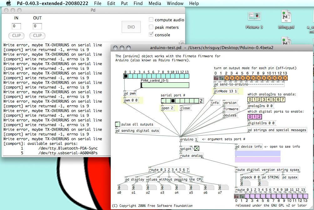
i dont know why all those errors happen. but click the "devices" message box in there to check what port your arduino is on.
hans is pretty awesome for making this patch, its really easy to understand i think.
change your port to whatever pd tells you your arduino is on.
HUZZAH! CONNECTIVITY!
now, lets say we still have that LED plugged in. want to test it?
hit that "pulse all outputs" toggle, and it should blink on and off. look around that subpatch, its pretty simple too. (you will want to know all these messages to send when writing your own patch for stuff)
Input is easy too. turn on that little toggle under [arduino 1] to let through outlet info.
you'll also want to enable your analogIns in the yellow radio up there.
say you had a potentiometer you wanted to connect up, it's really easy. and a breadboard will make all your connections easier to make.
but you'd just connect it up like this.
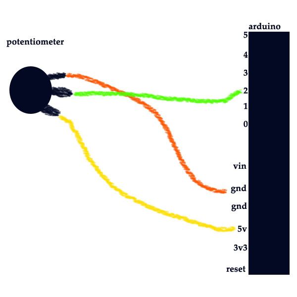
then you'd just enable the input you are using in that patch(input 2 in this case) and watch the input stream in through the a3 number box at the bottom.
this is how it works for me anyway.
that should just show you how the basics of it work, and you can move from there.
 posted in I/O hardware diy
Control analog sensor data in PD?
damn godinpants, that was exactly what i needed!! damn i'm excited now, its starting to work out! i also divided the soundfiler info by 100 and multiplied it to the signal before the [pack 0 100]. that made sure it worked for the full sound file instead of just 0-44100.
i have two sensors. one sensor is the scratcher: the soundfile is played fast/slow depending on how fast i move an object closer to the sensor. I dont know if that makes sense. is it possible to have the other sensor slow down the speed of the playback??
for instance, i have a 10 second file. i made the vertical slider range from 20-100 because that's the range the signal is clearest. if i move my hand slowly closer to the sensor, the 10 second sound file plays forward. i want the other sensor to "zoom" into the vertical slider and make, for instance, the 20-30 range the range that the 1st-scratcher-sensor is working with. if my left hand is using the 2nd "zoom" sensor, and my right hand is using the 1st "scratcher" sensor, my left hand will pinpoint a section of the sound file that i want my right hand, the scratcher, to play back and forth.
Whats the best way to do that? (sorry for the long detailed messages, i just try to make sure you guys understand my situation)
 posted in technical issues
Control analog sensor data in PD?
Hi! There is so much documentation online, but i still cant seem to figure this out:
I have a sharp gp2d120 sensor hooked up to my arduino. The arduino has firmata 2.0 installed so that it can communicate to PD (using pduino). I am getting a steady stream of voltage data from the sensor (as you can see from the the 4th analog pin in the screenshot). I'm trying to figure out how i can turn this data into something i can work with. Or maybe i need to learn how to work with it. Ultimately i want to control the frequency of a sound file based on the voltage output of the sensor (which is relative to the proximity of an object to the sensor).
So how can i convert this analog data into something i can work with (some data type that i can [delay] and that i can output to [dac~]? Do i need to use [mtof] to convert it to frequency? Do i need to turn it into a MIDI device somehow? [ctlin]? [tabread4]? These are just some objects that have come up after i searched for solutions, but i don't know how to execute it all.
side note: is it possible to set the sample rate of arduino in PD? the sensor works best with 10ms intervals between each sample.
posted in technical issues