PDuino - simultaneous analog input and digital output problems
Hello!
I'm trying to get PDuino working in a setup where I have Arduino reading an analog input and also controlling a relay on the digital output. I have tried the StandardFirmata sketch for Arduino but it doesn't seem to be able to read the analog input with this sketch (it controls the digital output no problem with this however). When I use the AllInputsFirmata instead, it reads the analog inputs just fine but I'm getting no response on the digital outputs.
Is there perhaps something where you can't use analog inputs and digital outputs at the same time? Could I be doing something else wrong? I've tried all the other Firmata sketches that come with the Pduino setup files (out of desperation!) but with no success. Any help greatly appreciated!
 posted in technical issues
How to use OSC namespaces in MobMuPlat?
Is it possible to parse the namespace of OSC messages in MobMuPlat?
MobMuPlat handles OSC communication in a wrapper patch that provides a message called 'fromNetwork'.
Say the OSC message is: /level1/level2/levelN format value
It has the format: [path format value]. The path here uses a namespace that subdivides according to levels.
With oscparse, the namespace in the path could be parsed like this :
netreceive -> oscparse-> list trim -> route level1 -> route level 2 ... route levelN
https://forum.pdpatchrepo.info/topic/9856/oscformat-and-oscparse-integer-not-routing-as-expected/8
With MobMuPlat's 'valueFromNetwork', is it still possible to "route" the value of the message according to the namespace? Since valueToNetwork contains a list where the first argument is the entire path, I can only split the first argument from the remaining arguments:
receive fromNetwork -> route list -> route /level1/level2/levelN
But I can't further split within the path itself to divide leve1/level2/levelN:
receive fromNetwork -> route list -> route .level1 -> route level2 -> route levelN.
Is there a way of doing this?
 posted in technical issues
Audio Settings for multichannel with MOTU 828 mk3
Hi Matthieu,
I see your post is a little bit old but I'm experiencing the exact same problem now with my setup.
I'm using a Windows 7 machine with a MOTU 828x sound card connected via USB to the PC and Pd 0.48.1 vanilla.
Here what I've done:
- I've checked the "Use Stereo Pairs for Windows Audio" inside the "MOTU Audio Console";

- opened PD and selected "standard MMIO" as driver from the "Media" menù;
- now here's the list of outputs as it appears from the drop-down menu of "Media/Audio Setting.../Output device":
- MOTU Analog 3-4
- Loudspeakers (devide High ...
- MOTU Main-Out 1-2
- MOTU ADAT optical A 3-4
- Digital Output MOTU Audio
- MOTU ADAT optical A 1-2
- MOTU Analog 1-2
- MOTU ADAT optical A 7-8
- MOTU ADAT optical B 3-4
- MOTU Analog 7-8
- MOTU Analog 5-6
- Digital Output
- MOTU SPDIF 1-2
- MOTU ADAT optical B 1-2
- MOTU ADAT optical A 5-6
- MOTU Phones 1-2
As you see this list is pretty messed up and the names of logical consecutive output channels are not consequential. I would like to have 8 analog outputs from my MOTU so I selected the first item on the list (MOTU analog 3-4) then specified a total of 22 channels.
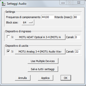
I'm obliged to set 22 as the total number of output channels because in my list MOTU Analog 5-6 are the last analog elements present. Because items in the list represent pairs of channels, this item corresponds to logical channel 21 and 22.
- Then I created the dac object this way:
[dac~ 13 14 1 2 21 22 19 20]
Here's an image
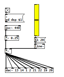
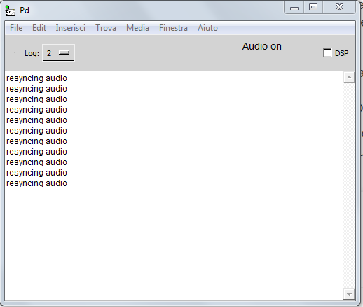
This way I'm able to hear sound on all analog outputs of the MOTU even if I'm experiencing variuous 'clicks' and a series of "resyncing audio" messages inside the PD console...
I confess, this method is the only way I'm able to make this setup work but it seems to me to be pretty messy and not intuitive at all.
What seems to be even worse is that analog audio outputs inside the device list seems to change their order at each computer restart, so every time I have to restart from scratch.
- Is there some easier solution to this problem?
- Maybe a preference file I can create for PD to load at each startup containing all these settings?
- or there may be a way to programmatically select correct "analog outputs" from the device list in my patch (even if string parsing doesn't seem to be so easy in PD to me).
- Would launching PD from console, maybe from an ad-hoc script, solve the problem?
Thank you so much for your support
M
 posted in technical issues
Build a MIDI controller with the Arduino, Firmata and Pure Data
Time to start contributing some knowledge back to the wonderful world that is the internet; today, a step by step nice and easy tutorial on getting started to building your own MIDI controllers with the arduino.
When researching for my ableton controller project, I didn’t find much out there about using firmata on an arduino to send data to software. The standard approach just seemed to be create the code in the arduino language, upload it to your board and hack one of those MIDI to USB cables as a bodge job way of getting the MIDI out of the arduino.
So why firmata and pure data? Well the whole idea of firmata is that you flash it to your arduino, and it throws out serial about whats going on with the arduino inputs and outputs, then you decide how the software treats the readings coming in and going out.
Theory out the way, lets build some controllers. You’ll need a few things…
HARDWARE:
An arduino and something to wire into it (for this i’ll be using a pot)
A USB cable for your arduino
SOFTWARE:
Arduino – http://arduino.cc/en/Main/Software
Pure Data – http://puredata.info/downloads
Firmata – http://at.or.at/hans/pd/objects.html#pduino
Something to patch your new controller into; like Reason or Ableton Live
- SETTING UP FIRMATA AND PURE DATA
Install Pure Data and create a folder to store all your patches somewhere. Unzip Firmata and add the files ‘arduino.pd’, ‘arduino-test.pd’ and ‘arduino-help.pd’ to your new Pure Data folder. The ‘arduino.pd’ file is the object that we use in PD for opening up communication with your arduino and routing it to PD. Done? Awesome, your software is almost set up.
- FLASHING FIRMATA TO YOUR ARDUINO
Install the latest version of arduino and open it up. Connect your arduino with the USB cable to your laptop (i’m using a macbook for this by the way). In the example patches, open up “Standard Firmata”, select your board (im using an arduino mega), and your serial port (look for tty.usbserial for use with a USB cable). Then compile and hit the upload button and your arduino is now ready to use firmata and communicate with Pure Data!
- WIRING UP A POT
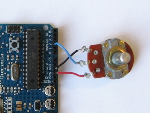
Potentiometers are cool, and theres a great arduino tutorial of how to wire one up here: http://www.arduino.cc/en/Tutorial/Potentiometer
Basically, all you need to know is that there are three pins; your two outer pins govern voltage flow across the pot, meaning one has to be 5V and the other has to be ground. It doesn’t matter which, but your 5v pin is going to be where your pot reads maximum, so convention dictates this should be the right hand pin. The center pin needs to be connected to an analog in on the arduino and will read the value of the pot as it sweeps from ground (0v) to 5v.
All wired up? Plug it into your laptop and open Pure Data, we’re ready to get things talking.
- SETTING UP OUR PATCH
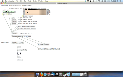
Open the example “arduino-test.pd” Pure Data patch you copied over earlier. It should look like this one…
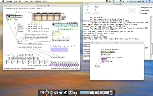
The test patch has everything we need to open a connection and enable pins. Firstly, lets delete a bunch of stuff and make our window a bit bigger. Hit Command + E to enter edit mode in Pure Data.
Ok a quick explaination; the key component here is the ‘arduino’ object. This is being drawn from the file you copied in earlier, and is what communicated with your arduino. Here we can do everything to control the arduino from opening a connection, to receiving data.
The large grid allows us to set the mode of each pin on the arduino. Remember pins 0 and 1 are reserved for Rx and Tx. I’m using analog pin 4 for this demo, so I’ve set my pin mode for pin 4 to ‘analog’.
Now we can plug our arduino in and get a reading from the potentiometer.
- ARDUINO INTO PURE DATA
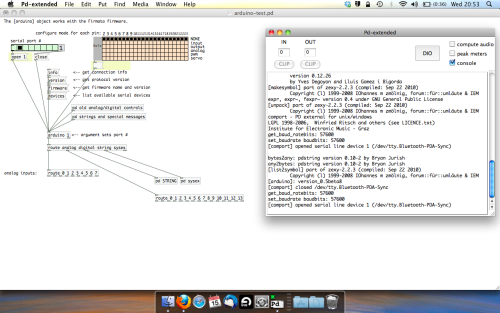
With your arduino plugged in, hit command and E to bring us out of edit mode. In our patch, click on ‘Devices’ above the arduino object and open up the pure data terminal. (That other thing that loads with PD that has all the scary code in)
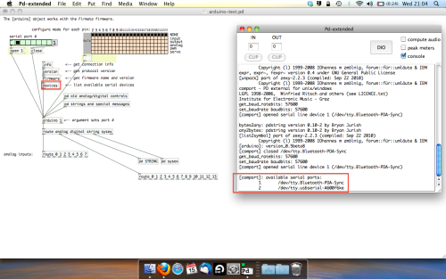
The “Devices” message connected to the arduino object pings your computer to find what devices are connected and on what serial ports. Since we’re using a USB cable to connect our arduino, we’re looking for something with ‘usbserial’ in it, in this case; port 2.
Select the relevent port in the green box at the top (remember the first box is ‘0’, second is ‘1’ and so forth) and hit ‘Open’ to establish a connection. Check the terminal to see if the connection was sucessful.

Now lets check we’re getting something in. Create a number box (Command + 3) and connect it to the relevent pin on the ‘Route analog’ box at the bottom. In this case, pin 4.
One more thing; if you’re not getting any readings in, you’ll need to click on ‘pd old analog/digital controls’ and enable your pins here too. What I tend to do in my patches is just not include the large grid but make my own ‘old pd’ controls custom to what i’m enabling/disabling to save space.
Here’s what the ‘old analog/digital controls’ subpatch looks like (pin 4 enabled)…
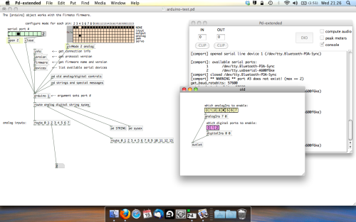
Come out of edit mode and check that you’ve got readings. If so congratulations! If not, troubleshoot, start with making sure your usb connection is opened, make sure all the correct pins are enabled (remember you’re counting from 0 not 1 on most of these buttons in PD, it’s just the way computers work).
- SCALING READINGS TO MIDI
So we’ve got a reading and chances are it’s to 3 decimal places between 0 to 1. No problem, create a new object (Command + 1) and type “autoscale 0 127”. This allows us to scale the input to a min and max value, in this case 0 to 127 of MIDI. Next, lets get things looking nice, create a new object and type “knob”. Connect this AFTER the autoscale object. (the knob is default set to read inputs from 0 to 127. Then create another number to display the scaled MIDI data coming out, and finally a new object and type “ctlout 1”.
It should look something like this…
The second box should be outputing values from 0 – 127 now, and the knob giving a visual representation of your potentiometer.
Now lets patch it into ableton…
- PURE DATA TO ABLETON LIVE
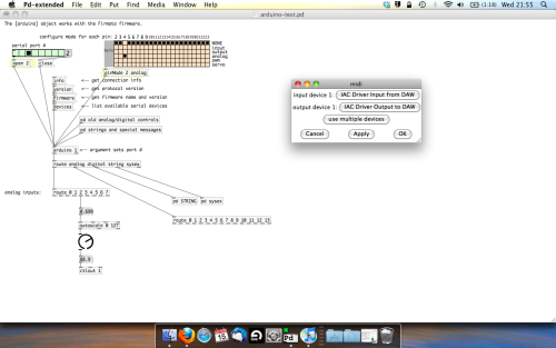
Firstly, you’ll need to set up your macs IAC driver if you’ve not done this. Basically you’ll need to go into Audio/MIDI preferences and enable your IAC driver. Then create a new input and output. One for input to DAW and one for output from DAW. Google around for a tutorial on this, its really simple, a 30 second job.
After you’ve set up your IAC driver, go back to PD and go to preferences > MIDI Settings, and connect your IAC driver.
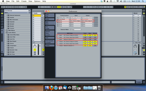
Open ableton and go to its MIDI preferences. Create a device listing for your IAC driver and enable its ins and outs into ableton like so…
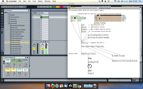
And thats it! Create an instrument and try to assign something! I’ve got it controlling the brightness of a bass sound here.
Shout out for Facu who requested this tutorial. Hopefully it’ll help some of you looking to get into this stuff and start building things but with no idea where to start.
 posted in tutorials
Pduino + Arduino Output to Pins
Dear Forum,
Experienced PD user, intermediate Arduino user here.
My goal is to send several different frequency square waves (to be used as "on" and "off" signals for a circuit) to various output pins on an Arduino.
I am up and running using the Pduino library, and have PD and Arduino talking to each other.
However, I am not able to output audio-rate signals to any Arduino pins. For example, sending a square~ into an appropriately timed snapshot~ to output 0's and 1's to Arduino pins yields random clicking/sputtering Arduino output, rather than the expected steady square wave tone at any freq.
My arduinos play a square wave out through the pins just fine when using the Arduino IDE...so, what am I missing in the communication between Arduino and PD/Pduino? A speed issue?
Thanks in advance for any advice!
 posted in technical issues
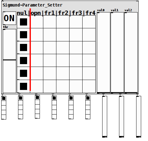
Sigmund~ Parameter_Setter: Use guitar notes to set patch parameters
Sigmund~Parameter_Setter: Using guitar notes to set patch parameters
sig-setter~-help.pd
sig-setter~.pd
Preface: I have been doing a lot of work recently setting up an electric guitar as an "arduino guitar" (with additional knobs, switches, etc.) to run my patches.
Occurred to me a couple of days ago (while considering buying a second ard to make a guitar for a friend), I could harness sigmund~ to just capture pitch (as digital values) and envelope (as the analog values) without ever changing the inside of the guitar.
The result is this patch.
Instructions:
The [ON] toggle triggers a [switch~] and would be used during setup and (probably) not performance (without severely cramping one's playing style).
The grid of hradios represent the fret board (in standard guitar tuning). Low on the bottom, high on the top.
The first three (bottom hradios) strings (low-E,A,D) run from midi-pitch 40 thru 54. So if you play for example pitches 40-44, it changes the first string hradio between the values of 1 and 5. The A and D strings do the same but for their respective hradios. (The first 6 outlets (from left to right) represent the 6 strings).
The three high strings also capture hradio values. But in the special case of being in "open", (using the [env~], in other words how loudly you play the note) they send analog values between the range of 0 and 1 (as shown in the val0, val1, and val2 sliders and are sent to the right three outlets). So if you play the note loud it sets the parameter/slider closer to 1, softer closer to 0.
The "threshold" (sigmund~ minpower param) is used to filter for ambient noise and add sensitivity control and defaults to 66. So it can be set to capture the softer sounds and change the range of the analog values. (It's max is 100. Changing that value would need to be done internally within the patch).
I am pretty sure if configured properly, this makes my arduino guitar idea mute.
On the other hand, I love to play with knobs and switches  so am Not going to abandon that tool for this patch.
However, I think this patch might prove useful to others.
If not to actually use, then at least for the sake of an idea-generator about how to use the fretboard (potentially instead) of arduino to set param values.
Happy Pd-ing,
Scott
p.s. This is setup to use standard guitar tuning but other tunings could easily be fashioned.
You can see the effect in action by clicking on the messages (which represent (midi) pitches)) at the top right of the help file. Changing the "gain(log)" before clicking a message impacts the analog values.
p.p.s. Sorry, it's so large, but my eye-sight is very poor and this scale just makes things a helluva a lot easier on me.
afterward:
If it bounces between values on you, try (in this order): a cleaner sound (un-effected), changing the threshold, or if necessary the parameters inside the sigmund~ object.
 posted in patch~
Getting DHT-22 sensor data to PD/PD-l2Ork RPi3
Hello, first post here as a PD newbie (but Max veteran) ")
I have managed to get PD working on my RPi3 (well that was easy as it is included in the Rasbian repository!!) and I am currently installing PD-l2Ork. I hate to ask stuff without having had a good stab at it myself already but I just wanted to ask for tips on getting sensor information into PD.
I am going to take part in Tiree Tech Wave in a couple of weeks and I want to make some kind of reactive bio feedback sample player, trying to scrub local weather data looks like it might be quite hard so I thought of doing something a little more micro scale and use something like the DHT-22 to get local ambient data and to influence a generative system that plays back samples from file.
I am fairly competant with Arduino style C and have done a little work in Python (but Python does give me a headache!!) - I have managed to get DHT-22 collecting and feeding back data on the RPi with Python and on the Arduino individually. I have no idea right now how to go about getting that data into PD...
The DHT-22 has a basic microprocessor on it that sends the collected ambient readings as words on a single wire data line, People have made nice Arduino and Python libraries already to handle that painlessly...
I have installed pd-comport and I have the impression the PD-l2Ork has some good included GPIO handling, I think that what I could do quite easily right now is bring an Arduino along as well and get the Arduino to handle all the DHT-22 stuff, and also react to the data - this could result in something like triggers activating on several GPIO pins, all easy stuff. But it would be nicer and I would learn more if I could send the actual numbers based on temperature and humidity to PD and do stuff there... I have no idea how easy that would be, in Max/MSP I would use the serial object to get data from the Arduino, and it's pretty easy to filter what you see at either end.
I guess another possible benefit of serial is perhaps using Bluetooth and having the sensor located more remotely.
Of course, it's probably totally unnecessary to use an Arduino and it can all be handled by the RPi but using Python makes my blood pressure go up 
Anyway, woops I have written an essay... any thoughts, tips or words of encouragement would be welcomed!
 posted in I/O hardware diy
Using pduino and Firmata to read values from the Grove I2C Touch sensor
Hi @alexandros
code is below, if you can figure anything out that would be great !
/* GroveI2CTouchTest.pde - Sample code for the SeeedStudio Grove I2C Touch Sensor
http://seeedstudio.com/wiki/index.php?title=Twig_-_I2C_Touch_Sensor_v0.93b
Prerequisite: A modification of the Grove I2C Touch sensor is needed Solder a pin to
the INT terminal in the I2C sensor to connect it to one pin in Arduino  Created by
Wendell A. Capili, August 27, 2011. http://wendellinfinity.wordpress.com
Released into the public domain.*/

#include <Wire.h> // include I2C library
#include <i2c_touch_sensor.h>
#include <MPR121.h>
// include our Grove I2C touch sensor library
// initialize the Grove I2C touch sensor
// IMPORTANT: in this case, INT pin was connected to pin7 of the Arduino
// (this is the interrupt pin)
i2ctouchsensor touchsensor; // keep track of 4 pads' states
//boolean padTouched[4];
long previousMillis = 0;
long interval = 100;
void setup()
  {
    Serial.begin(9600); // for debugging
    Serial.print("begin to init");
    Wire.begin(); // needed by the GroveMultiTouch lib
    touchsensor.initialize(); // initialize the feelers     // initialize the containers
    //for(int i=0; i<=3; i++)
    //{
   // padTouched[i]=false;
    //}

  }
void loop()
{
   unsigned char MPR_Query=0;
   unsigned long currentMillis = millis();
 if(currentMillis - previousMillis > interval)
  {
    previousMillis = currentMillis;
    touchsensor.getTouchState();
  }
 for (int i=0;i<12;i++)
 {
 if (touchsensor.touched&(1<<i))
    {
    Serial.print("pin ");
        Serial.print(i);
        Serial.println(" was  touched");
         }
 }
}

/*

  touchsensor.readTouchInputs(); // test read the touch sensors
// loop through our touch sensors 1 to 4
  for(int i=0; i<=3; i++)
  {
// get the touch state based on pin #
    if(feelers.getTouchState(i))
    {
      if(!padTouched[i])
        {                    // print in serial that it was touched
        Serial.print("Pad ");
        Serial.print(i);
        Serial.println(" was touched");
        }
// flag the touch sensor state
    padTouched[i]=true;
     }
    else
    {
    if(padTouched[i])
    {
      // print in serial that it was released
      Serial.print("Pad ");
      Serial.print(i);
      Serial.println(" was released");
    }               // reset the touch sensor state
    padTouched[i]=false;
    }
  }*/
 posted in technical issues
Pduino-based multi-arduino wireless personal midi controller network
Saw your TED video, so maybe you've already solved this problem. ")
In my limited work with getting arduino and pd to play nice, I've found that things like pduino and firmata work great but can be restrictive. I had to multiplex inputs on my arduino, which doesn't play nice with something like firmata that automatically reads all the pin values.
It might be better to have each arduino on it's own [comport], and differentiate the arduinos that way. Dump pin values over each comport and keep reading it.
Here's the thread explaining what I did:
http://puredata.hurleur.com/sujet-5832-reading-multiplexed-input-streams-arduino
I'm a fan of your work.
 posted in I/O hardware diy
Pure Data and Arduino
Hello,
Although there seems to be endless information on the internet on using an Arduino board with Pure-Data, I haven't found any info that will make it work for me... So, I'm seeking for some help.
So I'm trying to use my Arduino board to read galvanic skin response. I've got that nearly working. Where I'm having trouble is getting the data into PD in the correct format.
Here is the code I have for my Arduino:
// Arduino Code
int sensorPin = A0;
int sensorValue = 0;
void setup() {
Serial.begin(9600);
}
void loop() {
float conductance = getVoltage(sensorPin);
Serial.println(conductance);
Serial.write(conductance);
delay(1000);
}
float getVoltage(int pin){
return (analogRead(pin));
}
// End Arduino Code.
I'm using the comport object in PD. And I am receiving Data which is analogous to what I'm doing on the board. But I can't understand exactly what it is reading. Here is the link to my PD patch: http://www.sendspace.com/file/n81jlj
So Firstly, the Numbers keep jumping around, and secondly I'm not sure what those numbers are. What I'd like them to be is the individual analog inputs of my Arduino. But they clearly aren't as they all change when I play around with my arduino board. Also they seem to range between 0 and 255, whereas my Arduino reads the data as 10bits...
Any sugestions!?
Thank you,
Niko.
 posted in I/O hardware diy