Windowed-sync oscillator: Style questions
- Is [fexpr~] the best way to check for the phasor reset?
I did it in the same way, or with Cyclone.
@jameslo said:
I think you and I were posting on another topic when @alexandros suggested using [rzero_rev~ 0] to get the previous sample.
cool
- The [rpole~ 1] is essentially a phasor with a signal-rate reset (as opposed to [phasor~], which can be reset, but only with control messages). Is there a better way?
There are [vphasor~], [vphasor2~] and [vsamphold~] from @Maelstorm . I did not try them yet.
https://forum.pdpatchrepo.info/topic/10192/vphasor-and-vphasor2-subsample-accurate-phasors/
Patched my own [vphasor~] with [fexpr~], too and another one with a [pd subpatched] [block~ 1] and [tabwrite~] and another [pd sub] [block~ 1] [tabreceive~] and a feedback-loop, that is basicly forming a ramp by adding itself up.
Both might be expensive? I did not compare their CPU load yet.
Your [rpole~ 1] is neat.
Why not in vanilla?
I am wondering about this, too. Am working on sampleaccurate "audio-control" and slowly making progress.
In your patch [rpole~ 1] is working with a signal-inlet, isn't it?
Or what is it that you tried to say?
Of course you can deform the ramp with [*~] [+~] [samplerate~] ect.
Which is that other forum you mentioned? I am keen to learn more about DSP techniques.
(Tbh I'm a little bit proud of this one
)
yeay!
 posted in technical issues
tabwrite~ that is drive-able by a sample index
I would like to write a signal into an array (tabwrite~) and I want to know at all times exactly which sample index is being written.
In SC I would do this with:
var phase = Phasor.ar(0, 1, 0, BufFrames.kr(bufnum));
var signal = ... something...;
BufWr.ar(signal, bufnum, phase);
In Pure Data.... [tabwrite~] takes no phase inlet. Nor does it provide a phase outlet.
I could do a sample-by-sample integrator with [rpole~ 1] but then... how to reset it exactly at the end of the array? I could just let it integrate for a few minutes, but without resetting, it will hit the limits of floating point precision after 6 minutes or so. So it needs to be reset.
[phasor~ (1 / array duration in seconds)] --> [*~ array frames] gives fractional sample indices, which of course does not accurately reflect sample-by-sample integration of DC = 1 -- therefore rounding error will eventually kill this approach.
Is there an external to do this?
My intention was to make a demo of recording into a circular buffer and catching event onsets with bonk~, saving the sample indices into a list to use with a buffer player. This presumes accurate knowledge of the buffer position being written to at any moment. That's the rationale for the question.
hjh
 posted in technical issues
[bang~] bangs before the end of a dsp block at startup
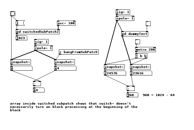
@Nicolas-Danet OK, I think I get it. 1024 samples have "passed" (according to the phasor~ counter) inside the reblocked subpatch because sample processing lurches forward 1024 samples once every 16 64 sample blocks processed by the enclosing patch. My error is in thinking that sample counters should all progress at the same rate, like two different wall clocks would. When dsp processing starts, PD arranges all subpatches regardless of blocking to immediately start generating audio if necessary, so in the case of a 1024 sample reblocking, it just fills the first 960 samples with 0's so it can start outputting them. But it has to wait for the first 64 real samples before it has a complete 1024 vector to process.
RE the array, you can force the drawing by either clicking on it somewhere (and ignoring the point you just created), or by just leaving the subpatch closed and opening it when you want to take a look. There is also list view, which is the only way I knew that the discontinuities were on 64 sample boundaries. So it's less the array GUI element that I'm concerned with, and more the behavior of [tabsend~]. [tabreceive~] is used to implement things like Hann windows, so it has to enforce a 1-1 ordered correspondence between the source table and the current vector. I assume that [tabsend~] makes similar guarantees, but I was wondering if the switch~ was messing things up. The message to turn on dsp can come between any 64 sample block, could that be related to the timing of the discontinuity I'm seeing? When dsp is off, does PD stop accumulating the 1024 block for the subpatch? The discontinuity goes away when I declare [switch~ 1024 16 1], and it also causes the phasor~ counter to report approx 64 (because phasor~ is configured in cycles per second and so has to adjust to the current blocking, overlap, and oversampling). <BS in last sentence corrected/>
 posted in technical issues
[bang~] bangs before the end of a dsp block at startup
@Nicolas-Danet He he, no need to apologize, I'm grateful to get anything, BS or otherwise, in response to my own BS ")
Your explanation is consistent with the 64 sample result seen from the outside, but the phasor~ counter on the inside clearly runs 1024 samples before the [bang~] takes a snapshot and stops the subpatch. I'm not sure how to connect those two observations.
Here is yet another test, one that combines the two from the last test, but also tries to determine when samples start coming into the subpatch.
switch~ vs bang~2.pd
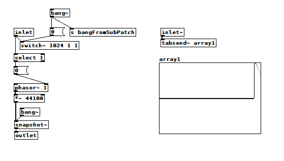 I got this result by starting dsp after clicking on the bang button and checking both toggles. The array1 inside the subpatch clearly shows only the last 64 samples populated by the [tabsend~], yet the outlet still passes 1023, meaning the phasor~ did count 1024 samples from 0. If I start dsp before clicking/checking, then array1 is completely filled but always has a discontinuity at some 64 sample boundary. For an FFT, there wouldn't be a discontinuity as long as I was inputting a static periodic signal of some harmonic frequency.
That other test on the right shows that there is a 960 sample latency through a 1024-blocked subpatch. That 64 sample difference has got to be related, but I can't understand how.
posted in technical issues
[writesf~] problem
A couple of illustrations.
Let's say we want a sine wave covering 16.5 samples. To illustrate, I used SuperCollider to put two sine wave cycles into 33 samples.
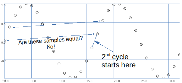
The second cycle begins when the wave crosses the 0 line in the middle.
This is between samples.
So, the second cycle must be represented by sample values that are different from the sample values for the first cycle.
That is, it is possible to have that zero crossing between samples -- but the sampling process produces different values.
Let's look at it a different way: blue samples = one sine wave cycle covering 33 samples; green samples = 2 cycles in 33 samples.
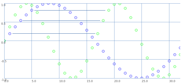
If we start counting samples at 0:
- Blue 0 = Green 0.
- Blue 2 = Green 1.
- Blue 4 = Green 2. etc.
That is: read through the blue samples at double speed, and you get the 16.5 wavelength. (This is exactly what David said.)
What about the second cycle starting at 16.5?
- Blue 1 = Green 17.
- Blue 3 = Green 18. etc.
These are the sample values that were skipped the first time.
So, Green 17 (the first concrete sample value after the second cycle begins) is the value in between Green 0 and Green 1. Green 18 is in between Green 1 and Green 2.
This is interpolation.
Interpolation is the mathematically correct way to represent fractional cycles in a sampled signal.
You can try to say that this "isn't the real problem," but... this is the problem, and interpolation is the solution.
hjh
posted in technical issues
[writesf~] problem
Hi
It is not easy for me to explain why I need maximum precision, either because of the complexity that would be explained to me and because my English is not entirely good. Although if I can try to explain a simple example (although it is far from the real purpose)
Suppose I have 2 audio samples. The first sample lasts exactly 1000ms (44100 samples) and I loop it every 1000ms.
If I had another exactly 125ms sample and looped it back at its exact time (125ms) alongside the first 1000ms sample, the beat would be perfectly in sync since it's the exact eighth part of 1000.
On the other hand, if I can only get a sample of 5512 samples (124.988..ms) and I loop it along with the 1000ms sample, as time progresses and the 124.988 sample is repeated more times ... ms, the desynchronization of time will increase ... (rhythm)
I know you can tell me that I can solve the "desynchronization" by repeating the sample every exact 125ms, but I have already said that this is just a simple example to try to explain and does not address the real problem.
As I have understood from your explanations, that sometimes it will be impossible for me to record samples to the exact duration that you want, but I can reproduce them within Pd exactly with the desired duration using the examples that you have given me. What invites me to think about the idea of not using any other means than Pd to get closer to my purpose, even if it takes more time and effort at first; But it is what I will do ..
Thank you
A greeting!!
 posted in technical issues
how can i make a [phasor~] myself?
my goal from doing this is to make a [phasor~], which only does one oscillation when it recieves a message, i can't simply use a line~ (at least AFAIK) to do this because i want to do FM on that [phasor~]. is there a way tho see what an object is made of, like opening a patch inside a patch, or is it just C code? i'm not good at C, BTW. could someone make a patch that does the same as [phasor~], or what i intend to do? both would be nice, because, if i just know haw the [phasor~] is made, i can probably transform it into what i need it for.
If none of the options above are possible, i have tried to use expr~/fexpr~ to time to turn off the [phasor~]/(output of [phasor~]), one attempt was with [fexpr~ if($x1[-1]==1,0,$x2[0])] where $x1 is the output of [phasor~], and $x2 is the frequency for [phasor~], and connect the output to [phasor~], but that didn't work. can somebody make a patch that reacts to [phasor~] reaching its peak: 1, and excactly between 1 and 0, when 1 is over and 0 has not started, and so turns the [phasor~] off?
help is greatly appreciated here:D
 posted in technical issues
3-op FM synth with mod matrix
@RandLaneFly Hi, I'll do my best to give you some replies:
- yes, offset just adds a fixed frequency in hertz regardless of the ratio or the note played. It's useful if you want to use an operator as an LFO;
- I used clip because the patch can receive values from external messages from the parent patch, the clip avoids unwanted values whatever you send to it. It's got to do with the GUI of the patch rather than with the synth itself;
- here is pphasor~.pd, it's just a phasor with sample accurate phase reset to be able to sync the operators accurately. I adapted it from some old patch I found, but I can't remember what I've changed to be honest. It only replaces phasor~ so you'd still need cos~ afterwards;
- about wrap~ and cos~: in a normal situation, where you do phase modulation with phasor and cos~, you don't need wrap~ because cos~ already wraps whatever phase it receives, even if it's outside the 0..1 range. In this case, instead of cos~, I used a table to store the waveform. Two reasons for this: 1) I wanted to be able to change the resolution of the sine and 2) I wanted to be able to use other waveforms other than a sine wave. Having said that, if your phase (after being scrambled around by all the modulators acting on it) has to address a table, you need it to be within the range of that table, otherwise you would be addressing points that are outside of the table (which would result in silence). This is why the phase is wrap~ped to the 0..1 range, and then multiplied by the length of the table in samples (4096 in this case);
- I don't understand what you mean by:
@RandLaneFly said:
But I take it after that it's sending out the phases to the tables, what is the purpose of the line being formed and sent into the right inlet?
The tabread4~ object is your output waveform for this specific operator you're looking at. Afterwards it's multiplied by the envelope (received on the right inlet of the *~ object), and then it's sent to the output (aka, what you hear) and to the phase tables.
- If by "the math in the table patch" you mean the fexpr~ object, that is exactly the same as found in the thread I mentioned in the first post. It averages the last two samples in order to filter very high, harsh frequencies in the feedback path. It's possible that FM8 uses a different filter, which would result in a different sound, but I have no way of knowing that.
I'm afraid the only resource I used for making this mess of a patch was that single thread about feedback, and then I expanded it for multiple operators. I very much like how it sounds, but it's incredibly expansive with polyphony, and on my computer 3 operators seem to be the limit, I wanted to try six but could never manage.
 posted in abstract~
PD's scheduler, timing, control-rate, audio-rate, block-size, (sub)sample accuracy,
@lacuna The whole patch is recompiled within Pd and I think that although the data flow model is fantastic it makes it harder to understand the workings.
The blocks (of audio) are read, or generated, and all of the stuff that the patch needs to do to the block is done all at once to every sample in the block, and then the block is sent onwards.
So if you put [x~ 2] >> [/~ 2] then nothing is done..... the code that Pd is running has done the math and the result is "multiply sample values by one".......... so "do nothing". A complex patch will have been boiled down to "subtract x from sample1" "add y to sample2" etc...... up to sample 64, rinse, calculate the next set of additions and subtractions to apply, and do it to the next block.
Those operations..... add to sample value... or subtract from sample value.... are the only possible operations on a sample value.......
Interpolation uses adjacent sample values for the calculation, but adding or subtracting to / from the sample values is what happens when the calculations have been done.
Some objects like [x~] can be controlled by a control signal, and so the new value can only be applied at block boundaries as the control calculations are done between boundaries. The addition will be the same for every sample in the block. Pd didn't know in advance what it's next value might be, so a ramp cannot be applied across the samples in this block.
Some objects though, like [vline~] are scheduling changes of value that will happen across the block, and future blocks, and may finish at sample 43 within a block. Programmatically it is saying, as part of the whole patch "add a bit to sample 1 (if it has a +ve value or subtract if -ve)) and a bit more to sample 2 etc..... etc... and then for the next block, when the audio program runs again add even more to the 1st sample etc..... until.
So it is sample accurate.
And of course if [x~] is controlled by [vline~] it will do as it is told and be sample accurate too.
You can add a start delay to [vline~] so that it's start point is sample accurate too.
 posted in technical issues
PD's scheduler, timing, control-rate, audio-rate, block-size, (sub)sample accuracy,
Hello, 
this is going to be a long one.
After years of using PD, I am still confused about its' timing and schedueling.
I have collected many snippets from here and there about this topic,
-wich all together are really confusing to me.
*I think it is very important to understand how timing works in detail for low-level programming … *
(For example the number of heavy jittering sequencers in hard and software make me wonder what sequencers are made actually for ? lol )
This is a collection of my findings regarding this topic, a bit messy and with confused questions.
I hope we can shed some light on this.


- a)
The first time, I had issues with the PD-scheduler vs. how I thought my patch should work is described here:
https://forum.pdpatchrepo.info/topic/11615/bang-bug-when-block-1-1-1-bang-on-every-sample
The answers where:
„
[...] it's just that messages actually only process every 64 samples at the least. You can get a bang every sample with [metro 1 1 samp] but it should be noted that most pd message objects only interact with each other at 64-sample boundaries, there are some that use the elapsed logical time to get times in between though (like vsnapshot~)
also this seems like a very inefficient way to do per-sample processing..
https://github.com/sebshader/shadylib http://www.openprocessing.org/user/29118
seb-harmonik.ar posted about a year ago , last edited by seb-harmonik.ar about a year ago
• 1
 whale-av
@lacuna An excellent simple explanation from @seb-harmonik.ar.
Chapter 2.5 onwards for more info....... http://puredata.info/docs/manuals/pd/x2.htm
David.
“
There is written: http://puredata.info/docs/manuals/pd/x2.htm
„2.5. scheduling
Pd uses 64-bit floating point numbers to represent time, providing sample accuracy and essentially never overflowing. Time appears to the user in milliseconds.
2.5.1. audio and messages
Audio and message processing are interleaved in Pd. Audio processing is scheduled every 64 samples at Pd's sample rate; at 44100 Hz. this gives a period of 1.45 milliseconds. You may turn DSP computation on and off by sending the "pd" object the messages "dsp 1" and "dsp 0."
In the intervals between, delays might time out or external conditions might arise (incoming MIDI, mouse clicks, or whatnot). These may cause a cascade of depth-first message passing; each such message cascade is completely run out before the next message or DSP tick is computed. Messages are never passed to objects during a DSP tick; the ticks are atomic and parameter changes sent to different objects in any given message cascade take effect simultaneously.
In the middle of a message cascade you may schedule another one at a delay of zero. This delayed cascade happens after the present cascade has finished, but at the same logical time.
2.5.2. computation load
The Pd scheduler maintains a (user-specified) lead on its computations; that is, it tries to keep ahead of real time by a small amount in order to be able to absorb unpredictable, momentary increases in computation time. This is specified using the "audiobuffer" or "frags" command line flags (see getting Pd to run ).
If Pd gets late with respect to real time, gaps (either occasional or frequent) will appear in both the input and output audio streams. On the other hand, disk strewaming objects will work correctly, so that you may use Pd as a batch program with soundfile input and/or output. The "-nogui" and "-send" startup flags are provided to aid in doing this.
Pd's "realtime" computations compete for CPU time with its own GUI, which runs as a separate process. A flow control mechanism will be provided someday to prevent this from causing trouble, but it is in any case wise to avoid having too much drawing going on while Pd is trying to make sound. If a subwindow is closed, Pd suspends sending the GUI update messages for it; but not so for miniaturized windows as of version 0.32. You should really close them when you aren't using them.
2.5.3. determinism
All message cascades that are scheduled (via "delay" and its relatives) to happen before a given audio tick will happen as scheduled regardless of whether Pd as a whole is running on time; in other words, calculation is never reordered for any real-time considerations. This is done in order to make Pd's operation deterministic.
If a message cascade is started by an external event, a time tag is given it. These time tags are guaranteed to be consistent with the times at which timeouts are scheduled and DSP ticks are computed; i.e., time never decreases. (However, either Pd or a hardware driver may lie about the physical time an input arrives; this depends on the operating system.) "Timer" objects which meaure time intervals measure them in terms of the logical time stamps of the message cascades, so that timing a "delay" object always gives exactly the theoretical value. (There is, however, a "realtime" object that measures real time, with nondeterministic results.)
If two message cascades are scheduled for the same logical time, they are carried out in the order they were scheduled.
“
[block~ smaller then 64] doesn't change the interval of message-control-domain-calculation?,
Only the size of the audio-samples calculated at once is decreased?
Is this the reason [block~] should always be … 128 64 32 16 8 4 2 1, nothing inbetween, because else it would mess with the calculation every 64 samples?
How do I know which messages are handeled inbetween smaller blocksizes the 64 and which are not?
How does [vline~] execute?
Does it calculate between sample 64 and 65 a ramp of samples with a delay beforehand, calculated in samples, too - running like a "stupid array" in audio-rate?
While sample 1-64 are running, PD does audio only?
[metro 1 1 samp]
How could I have known that? The helpfile doesn't mention this. EDIT: yes, it does.
(Offtopic: actually the whole forum is full of pd-vocabular-questions)
How is this calculation being done?
But you can „use“ the metro counts every 64 samples only, don't you?
Is the timing of [metro] exact? Will the milliseconds dialed in be on point or jittering with the 64 samples interval?
Even if it is exact the upcoming calculation will happen in that 64 sample frame!?
- b )


There are [phasor~], [vphasor~] and [vphasor2~] … and [vsamphold~]
https://forum.pdpatchrepo.info/topic/10192/vphasor-and-vphasor2-subsample-accurate-phasors
“Ive been getting back into Pd lately and have been messing around with some granular stuff. A few years ago I posted a [vphasor.mmb~] abstraction that made the phase reset of [phasor~] sample-accurate using vanilla objects. Unfortunately, I'm finding that with pitch-synchronous granular synthesis, sample accuracy isn't accurate enough. There's still a little jitter that causes a little bit of noise. So I went ahead and made an external to fix this issue, and I know a lot of people have wanted this so I thought I'd share.
[vphasor~] acts just like [phasor~], except the phase resets with subsample accuracy at the moment the message is sent. I think it's about as accurate as Pd will allow, though I don't pretend to be an expert C programmer or know Pd's api that well. But it seems to be about as accurate as [vline~]. (Actually, I've found that [vline~] starts its ramp a sample early, which is some unexpected behavior.)
[…]
“
- c)


Later I discovered that PD has jittery Midi because it doesn't handle Midi at a higher priority then everything else (GUI, OSC, message-domain ect.)
EDIT:
Tryed roundtrip-midi-messages with -nogui flag:
still some jitter.
Didn't try -nosleep flag yet (see below)
- d)

So I looked into the sources of PD:
scheduler with m_mainloop()
https://github.com/pure-data/pure-data/blob/master/src/m_sched.c
And found this paper
Scheduler explained (in German):
https://iaem.at/kurse/ss19/iaa/pdscheduler.pdf/view
wich explains the interleaving of control and audio domain as in the text of @seb-harmonik.ar with some drawings
plus the distinction between the two (control vs audio / realtime vs logical time / xruns vs burst batch processing).
And the "timestamping objects" listed below.
And the mainloop:
Loop
- messages (var.duration)
- dsp (rel.const.duration)
- sleep
With
[block~ 1 1 1]
calculations in the control-domain are done between every sample? But there is still a 64 sample interval somehow?
Why is [block~ 1 1 1] more expensive? The amount of data is the same!? Is this the overhead which makes the difference? Calling up operations ect.?
Timing-relevant objects
from iemlib:
[...]
iem_blocksize~   blocksize of a window in samples
iem_samplerate~  samplerate of a window in Hertz


------------------ t3~ - time-tagged-trigger --------------------
-- inputmessages allow a sample-accurate access to signalshape --
t3_sig~          time tagged trigger sig~
t3_line~         time tagged trigger line~


--------------- t3 - time-tagged-trigger  ---------------------
----------- a time-tag is prepended to each message -----------
----- so these objects allow a sample-accurate access to ------
---------- the signal-objects t3_sig~ and t3_line~ ------------
t3_bpe           time tagged trigger break point envelope
t3_delay         time tagged trigger delay
t3_metro         time tagged trigger metronom
t3_timer         time tagged trigger timer

[...]
What are different use-cases of [line~] [vline~] and [t3_line~]?
And of [phasor~] [vphasor~] and [vphasor2~]?
When should I use [block~ 1 1 1] and when shouldn't I?
[line~] starts at block boundaries defined with [block~] and ends in exact timing?
[vline~] starts the line within the block?
and [t3_line~]???? Are they some kind of interrupt? Shortcutting within sheduling???
- c) again)

https://forum.pdpatchrepo.info/topic/1114/smooth-midi-clock-jitter/2
I read this in the html help for Pd:
„
MIDI and sleepgrain
In Linux, if you ask for "pd -midioutdev 1" for instance, you get /dev/midi0 or /dev/midi00 (or even /dev/midi). "-midioutdev 45" would be /dev/midi44. In NT, device number 0 is the "MIDI mapper", which is the default MIDI device you selected from the control panel; counting from one, the device numbers are card numbers as listed by "pd -listdev."
The "sleepgrain" controls how long (in milliseconds) Pd sleeps between periods of computation. This is normally the audio buffer divided by 4, but no less than 0.1 and no more than 5. On most OSes, ingoing and outgoing MIDI is quantized to this value, so if you care about MIDI timing, reduce this to 1 or less.
„
Why is there the „sleep-time“ of PD? For energy-saving??????
This seems to slow down the whole process-chain?
Can I control this with a startup flag or from withing PD? Or only in the sources?
There is a startup-flag for loading a different scheduler, wich is not documented how to use.
- e)

[pd~] helpfile says:
ATTENTION: DSP must be running in this process for the sub-process to run. This is because its clock is slaved to audio I/O it gets from us!
Doesn't [pd~] work within a Camomile plugin!?
How are things scheduled in Camomile? How is the communication with the DAW handled?
- f)

and slightly off-topic:
There is a batch mode:
https://forum.pdpatchrepo.info/topic/11776/sigmund-fiddle-or-helmholtz-faster-than-realtime/9
EDIT:
- g)
I didn't look into it, but there is:
https://grrrr.org/research/software/
clk – Syncable clocking objects for Pure Data and Max
This library implements a number of objects for highly precise and persistently stable timing, e.g. for the control of long-lasting sound installations or other complex time-related processes.
Sorry for the mess!
Could you please help me to sort things a bit? Mabye some real-world examples would help, too.

posted in technical issues