Sample accurate control from DAW <--> PD ? With Camomile?
Hello,
i am wrapping my head around how to control PD-patches sample accurately from a DAW?
With Camomile?
As this is a bit confusing, could someone help with some light please?
For example:
** How to build a sample-accurate envelope, - triggered and modulated by a DAW? **
I am using Linux, so cross-routing with Jack is an option, too.
Probably somehow with [vline~] or [vphasor~]? This is sample accurate in the next block, isn't it? i.e. with latency-compensation in the DAW it is on point?
Open Sound Control is not sample accurate, is it? Seems like the PD-sheduler does not handle OSC synchronous!?
( How to trigger a set of control-rate objects by an audio-signal sample accurate? What would be the port / the transition between the two?
This isn't possible, is it?
I guess it is, with [pd]{ [inlet~] [block~1] [unsig~] [outlet] } and [vline~]? )
Do I need to patch the whole envelope with audio-rate objects?
i.e. [vphasor~] instead of [vline~]?
What is the way to go
to merge PD with a DAW sample-accurately?
DAW automation <--> PD control- and audio-objects.
And audio-intermodulation of DAW & PD?
 posted in technical issues
Sample control through phasor~
Hi there
I am playing back a sample based on the 'phasor~' object, where its modulation between 0 (start of sample) and 1 (end of sample) controls the sample playback/loop as seen in the first attached picture.
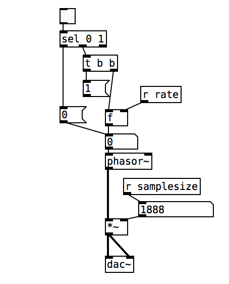
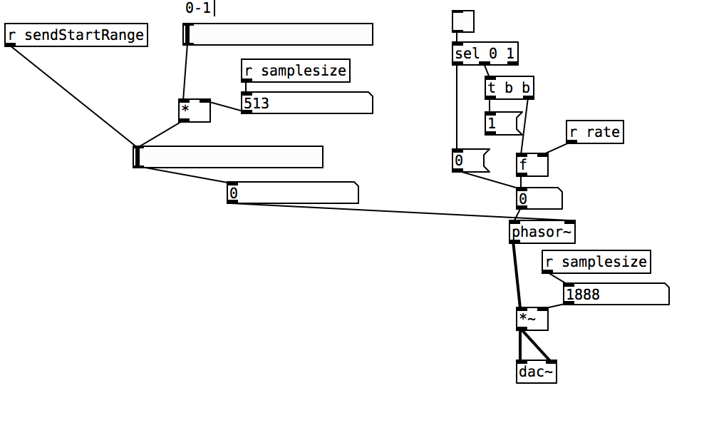
I have mannaged to control the samplesize and thus sample end, however, when wanting to change the start position of the sample playback I encounter problems. I have tried to control the phase as well as DC offset of the phasor (picture 2), however, it either only changes the sample start once in the loop and then goes back to 0 for the rest or does not change at all.
Is there anyone out there that has a suggestion on how to change the sample start in the loop, so that it loops from that point every time?
All the best
 posted in technical issues
Fm Synth Mod Matrix Help
thank you!!
okay, yeah. actually now that i understand better how vline~ works i guess it would be possible to phase sync without using the sample and hold method. if i'm sending pitch with a vline~ i have time to send a phase 0 message to my phasors. i should revise some of my lfo designs that use sample and hold reset for no benefit.
i just need to make sure i'm not reseting phase on a stolen note to avoid clicks.
i used to have a tx81z and a dx11 and i have a strange suspicion. they let you set a ratio for operator pitch, as normal. then, they let you choose one of 7 options for oscillator detune. you do not select detune in cents. this could mean that each voice only has one phase accumulator/phasor-like osc. the ratios are set by multiplying and wrapping that ramp before a sine shape. when detune is selected, it's possible the synth uses one of six cheap low-frequency beating oscillators to send to the phase inputs of all the operators that are set to be detuned.
 posted in technical issues
Possible audio file playback methods
@Transcend Ahh..... that is where the confusion arises. What is being read is individual samples.... at 44100Hz sample rate there are 44100 every second. The pitch is heard because of the rate at which they rise and fall in value.
In Pd a sine wave at 100 Hz would have a sample value of zero (maybe, it depends at what time the wave starts) at index 0, and then rising sample values to a value of 1 at sample number 110 (more or less) falling back to a sample value of 0 at sample 220, continuing to fall to -1 at sample 330 and then rising back to a value of zero at sample number 441....... etc. etc.
When those values are read by [tabread4~] the output would....... eventually, once it gets to your speakers..... push and pull the speaker smoothly 100 times a second, and be heard as 100Hz. Depending on the bit-depth of the dac the actual sample values later in the chain will be much larger, but Pd max/min values are +1/-1 at the output to the [dac~]. Your soundcard and Pd take care of that automatically.
If there is another sound, say at 1KHz., that would modulate that 100Hz wave..... it would look like a ripple on the 100Hz wave........ and so on. A music track will look a real mess when you look at it, with only loud / quiet parts really recognisable. But our ears, or more especially our brains, can make total sense of it.
Samplerate (audio) objects are used to set the indexes because they send a value at the samplerate...... so 44100 times a second...... so every single index is sent to [tabread4~]
Digital audio (FFT) is fiendishly complicated to understand, but this gets you quite a long way into it in only a few minutes........ https://medium.com/@djtech42/explanation-of-sample-rate-in-digital-audio-and-breakdown-of-misconceptions-38f912fb3b1f
Actually it gets you a very long way toward a good understanding in just a few minutes.......
David.
 posted in Off topic
Little help with pitshifter.
oh shoot! okay. I use a vline~ to feed tabread4~ so the method is a little different
The mtof part is designed to calculate a ratio - so if you input a zero into the left part, the result is one. If you input something like -5, it will give you a value that is less than one. You can multiply that value by the length of the sample in ms to get how long the sample would play back if you wanted it to play at 5 semitones above(?) the base pitch of the sample. You have to choose a midi note to start at. Above that note, the sample will play faster, below that note the sample will play slower. I think I calculate this value by taking the base note and subtracting from that the note from the midi keyboard.
You want to use the tabread4~ method from the (3.7.1.1.) example, but instead of feeding it with a phasor~, try feeding it with a vline~. Then you can calculate the length in samples of your sample. That's the left output of soundfiler. Dividing length in samples by the samplerate~ gives you the lenght of the sample in seconds. Multiply that by 1000 and you have the the length in milliseconds. vline~ takes input in milliseconds. Send it a message to ramp from 0 to the number of samples in your sample in the number of milliseconds you just calculated. If you want to repitch it, also multiply by the midi ratio from above.
If you want to use phasor~ instead, you're setting frequency in Hz. So instead of multiplying the sample length by 1000, you might want to multiply it by the ratio and then get the reciprocal of it with this:

Then feed that to the phasor~
Are you going to use phasor~ in your design? I could double check that there's not a better transposing method with phasor.
Actually, it might be way easier with phasor, You could convert your current input to phasor to midi with ftom, then add transposition in semitones and then convert back to a frequency...
posted in abstract~
Tabread4~~ example (or alternative)
@Gabriel-Lecup If you just want to loop at normal speed then you can use [tabplay~]
It will be sample perfect.
You just have to deal with waveform mismatch at the loop point..... which will cause clicks.
If you want to change the playback speed then you have another problem.
Artefacts are unavoidable. Well I will qualify that. As you reduce the playback speed you have to increase the original sample-rate of the Sample compared to your output sample-rate to avoid them. Half speed... double the sample-rate of the Sample. You cannot do that in Pd as far as I know.
If you cut the playback speed in half. This causes everything to sound an octave lower because the time stretching makes all the soundwaves twice as long, which means their frequencies will be cut in half and thus sound an octave lower.
This leads the problem that every single sample you use needs to be played twice or else there will be gaps (a much worse "artefact"). To avoid this problem you can use [tabread4~], which interpolates intermediate values that it generates using information from the values that ultimately precede and follow it.
If you increase the playback speed then samples are dropped. This unavoidably creates artefacts as well. As you say, with a tone they will be audible.
Filters can help with high frequency ringing, but might already be built into the object.... though probably not, because you can see the ringing in [B04.tabread4.interpolation].pd in the doc folder.
Someone might know whether [tabread4~] (or [tabread4~~] even), uses quadratic or cubic interpolation. Checking the processing overhead might tell you....... https://www.maximalsound.com/mastering/interpolation methods.pdf
You need to add 2 samples to the array for [tabread4~] ((see [tabread4~-help])) to do it's math playing back the whole sample.
I had never thought about it, but 2 zero samples should probably be inserted after a loop point to allow the curve to interpolate to zero. This would also avoid any post Sample clicks. But how?
I assume that [tabread4~~] which seems not to be available to me on windows, uses double precision.
That will give more accuracy for bit depth, but the samples still arrive at the same speed, so I cannot see how it helps you here. 64-bit precision interpolation over 32-bit precision. Audible? I would be very surprised.
If it is working well for the patch that @beep.beep has kindly posted then I can only assume that [tabread4~~] deals automatically with the 2 sample overhang.
David.
posted in technical issues
prophet 3003 wavetable synth prototype
hi folks, thanks for the kind comments!
sure ill share the patch eventually but right now its an uncommented messy laboratory affair. best thing you can do right now is look at the patch image above which is quite self explanatory.
here is the vs rom in one wav file, scan this in 128 chunks of 128 samples and you have the single wave data.
harmonic aliasing is best described by acreil in the above mentioned blog post because thats where i got the idea from. the rest is trial and error and a lot of listening to integer combinations.
harmonic aliasing is actually my own term for what im trying to do. here is how i would describe it:
-
if you repeat 128 samples with a phasor at 128 hz (or 64/32/16/8/4/2) or any multiple of 128 your phasor restarts exactly at the beginning of the wave data and the aliasing frequencies generated by the steppyness of the data will follow the harmonic overtone series 1,2,3 etc. depending on the multiple.
-
if you introduce another prime divider ie. 3 as in 128 / 3 the phasor will line up with the sample data every 3rd sample and the osc will alias at the 3rd subharmonic frequency which will be somewhat more disharmonic than any overtone.
-
another way to look at it would be the pattern repetitions. at subdivision 5 the phasor starts at 5 different points in the sample data and its easy to imagine that the readout patterns are all slightly different ... but the whole thing cycles after 5 phasor rounds = 5th subharmonic..
-
if you subdivide 128 further with a higher prime ie. 563 you will get 562 different sounding samples until nr. 563 lines up again. get the idea?
this is all very easy to hear once you experiment with prime subdivisions and multiplications. just remember its all based on synching the data flow from the sample with the frequency of the index phasor. this will work with ANY sample data, the vs rom is just cool to use for vintage synth fans.
whats important for proper aliasing is that you use a simple [tabread] into the data without any interpolation like tabread4 or oversampling!
all the other elements in the synth like delay, waveshaper, sequencer follow the same rule as they are just repetition devices like the wavetable oscillator.
if you finally synch everything to the sample rate of your soundcard the voltages that hit your speakers will repeat in exact patterns. thats the idea of this synth: precision number repetition controlled by harmonic/disharmonic integer combinations ... just like the great 80s synths waldorf microwave or prophet vs.
 posted in output~
[vphasor~] and [vphasor2~], subsample-accurate phasors
Hello everyone, long time no see.
I've been getting back into Pd lately and have been messing around with some granular stuff. A few years ago I posted a [vphasor.mmb~] abstraction that made the phase reset of [phasor~] sample-accurate using vanilla objects. Unfortunately, I'm finding that with pitch-synchronous granular synthesis, sample accuracy isn't accurate enough. There's still a little jitter that causes a little bit of noise. So I went ahead and made an external to fix this issue, and I know a lot of people have wanted this so I thought I'd share. ")
[vphasor~] acts just like [phasor~], except the phase resets with subsample accuracy at the moment the message is sent. I think it's about as accurate as Pd will allow, though I don't pretend to be an expert C programmer or know Pd's api that well. But it seems to be about as accurate as [vline~]. (Actually, I've found that [vline~] starts its ramp a sample early, which is some unexpected behavior.)
[vphasor2~] is [vphasor~] with an additional signal inlet. This inlet expects another positive-ramping phasor and is used for hard-syncing. When the phasor inlet gets a drop--as happens when a the phase cycle starts over--[vphasor2~] resets its phase to zero. It also does this with subsample accuracy by taking the last and first samples of the phase and estimating when it reset. That's why it needs a positive-ramping phasor as the input. If you try to hard-sync with a sine wave or something, it won't work.
As far as I can tell, everything is working, but let me know if you find a bug. I tried to document the code thoroughly as well.
The sources and helpfiles are included in the zip file. It uses the Makefile template, so just type "make" and it should compile.
vphasor.zip
 posted in extra~
FFT freeze help
Brace for wall of text:
My patch is still a little messy, and I think I'm still pretty naive about this frequency domain stuff. I'd like to get it cleaned up more (i.e. less incompetent and embarrassing) before sharing. I'm not actually doing the time stretch/freeze here since I was going for a real time effect (albeit with latency), but I think what I did includes everything from Paulstretch that differs from the previously described phase vocoder stuff.
I actually got there from a slightly different angle: I was looking at decorrelation and reverberation after reading some stuff by Gary S. Kendall and David Griesinger. Basically, you can improve the spatial impression and apparent source width of a signal if you spread it over a ~50 ms window (the integration time of the ear). You can convolve it with some sort of FIR filter that has allpass frequency response and random phase response, something like a short burst of white noise. With several of these, you can get multiple decorrelated channels from a single source; it's sort of an ideal mono-to-surround effect. There are some finer points here, too. You'd typically want low frequencies to stay more correlated since the wavelengths are longer. This also gives a very natural sounding bass boost when multiple channels are mixed.
Of course you can do this in the frequency domain if you just add some offset signal to the phase. The resulting output signal is smeared in time over the duration of the FFT frame, and enveloped by the window function. Conveniently, 50 ms corresponds to a frame size of 2048 at 44.1 kHz. The advantage of the frequency domain approach here is that the phase offset can be arbitrarily varied over time. You can get a time variant phase offset signal with a delay/wrap and some small amount of added noise: not "running phase" as in the phase vocoder but "running phase offset". It's also sensible here to scale the amount of added noise with frequency.
Say that you add a maximum amount of noise to the running phase offset- now the delay/wrap part is irrelevant and the phase is completely randomized for each frame. This is what Paulstretch does (though it just throws out the original phase data and replaces it with noise). This completely destroys the sub-bin frequency resolution, so small FFT sizes will sound "whispery". You need a quite large FFT of 2^16 or 2^17 for adequate "brute force" frequency resolution.
You can add some feedback here for a reverberation effect. You'll want to fully randomize everything here, and apply some filtering to the feedback path. The frequency resolution corresponds to the reverb's modal density, so again it's advantageous to use quite large FFTs. Nonlinearities and pitch shift can be nice here as well, for non-linear decays and other interesting effects, but this is going into a different topic entirely.
With such large FFTs you will notice a quite long Hann window shaped "attack" (again 2^16 or 2^17 represents a "sweet spot" since the time domain smearing is way too long above that). I find the Hann window is best here since it's both constant voltage and constant power for an overlap factor of 4. So the output signal level shouldn't fluctuate, regardless of how much successive frames are correlated or decorrelated (I'm not really 100% confident of my assessment here...). But the long attack isn't exactly natural sounding. I've been looking for an asymmetric window shape that has a shorter attack and more natural sounding "envelope", while maintaining the constant power/voltage constraint (with overlap factors of 8 or more). I've tried various types of flattened windows (these do have a shorter attack), but I'd prefer to use something with at least a loose resemblance to an exponential decay. But I may be going off into the Twilight Zone here...
Anyway I have a theory that much of what people do to make a sound "larger", i.e. an ensemble of instruments in a concert hall, multitracking, chorus, reverb, etc. can be generalized as a time variant decorrelation effect. And if an idealized sort of effect can be made that's based on the way sound is actually perceived, maybe it's possible to make an algorithm that does this (or some variant) optimally.
 posted in technical issues
Phasor Phase Problem
the reason this happens, is because you make a small logic error, in assuming that [t b b] will force the order of execution with the [phasor~] signal object. you are assuming that by using [t b b], that you're resetting the phase first, and then resetting the playback rate. However, signal objects work differently to control objects, and with [phasor~] any control message sent to the right inlet will only reset the phase when the current block is finished.
To ensure that the execution order works out the way you originally intended, the easiest way i can see is to force the [phasor~] reset when the [phasor~] speed is being set to zero. I checked this now, and it seems to work fine.
(by the way, i debugged your patch using [snapshot~] connected to a number box - that's a very useful tool for signal rate debugging)
 posted in technical issues