What's the 'delay' in preferences?
delay (msec) is to create the total buffer size. Its important for round trip latency where PD is looping the input to the output - the delay (msec) gets added with the block size (which for compatibility with other patches just keep at 64)
Usually JUCE based programs just give you a "block" of audio, PD is more under the hood about the DSP, the 64 block is a ring buffer that the main patch is at (which is why you have to subpatch to reblock) and the delay msec is padding for the CPU.
Normally you only run into it when you have to up the amount with the sine playing in 'Media, test audio and midi' when you first install PD until it stops sounding scratchy
but also theres another patch in the help browser under 7.stuff/tools/latency you can loop back the output of your audio to the in and play around with lowering it. Either with a loopback function on a dac, or like a wire plugged from out ot line or just have the mic and speakers setup where they could cause feedback if turned up too loud. Tests on the internet for mostly vintage DACS doing round trip latency were actually done in PD.
playing around with it I found Intel macs can go down to 3, and prosumer asio (like an old external edirol dac) can go down to the lowest, 2. Its up to the low level driver to give you the real round trip latency.
usually as long as you can get the sine wave to play in Media.. test audio and midi you are good. Its really only for processing audio in with minimal audible latency - super small delays go off the rails the second you really hit the CPU with polyphony, delay lines, small block sizes.
For a while I had it at as low as it was without being scratchy, but as I got into more complicated (and bloated) synth designs I just kept mine at 50 because when it was having problems more latency than that never helped but less could cause stutters/scratchy sounds.
Linux and Windows are usually set by default to 50 or 100 tho I dont have a problem above 23, offhand I think intel macs were set to 5 or 10. the new arm macs can run into a problem where the old default was too small and should have it higher as well. So the real winners were old intel macs.
use callbacks is only for some older audio drivers in linux
 posted in technical issues
Connecting and Unpacking or Routing from Arduino uno
* Hi everyone
I have searched around, I found any solutions that match my problem or are up-to-date unfortunately.
I’m having trouble unpacking and/Or routing the data coming in from sensors attached to my Arduino uno. The senses are working fine when I check the Arduino serial monitor before I began looking at the PD patch.
I just can’t seem to get them to unpack, or route in PD 0.5
Just wondering if anyone else has solved this - or has found this to be a problem?
Attached are images of two separate Arduino Scripps I’ve tried. One to try unpacking, the other to try routing - Plus, an image of my pure data patch to try testing the incoming signal data.
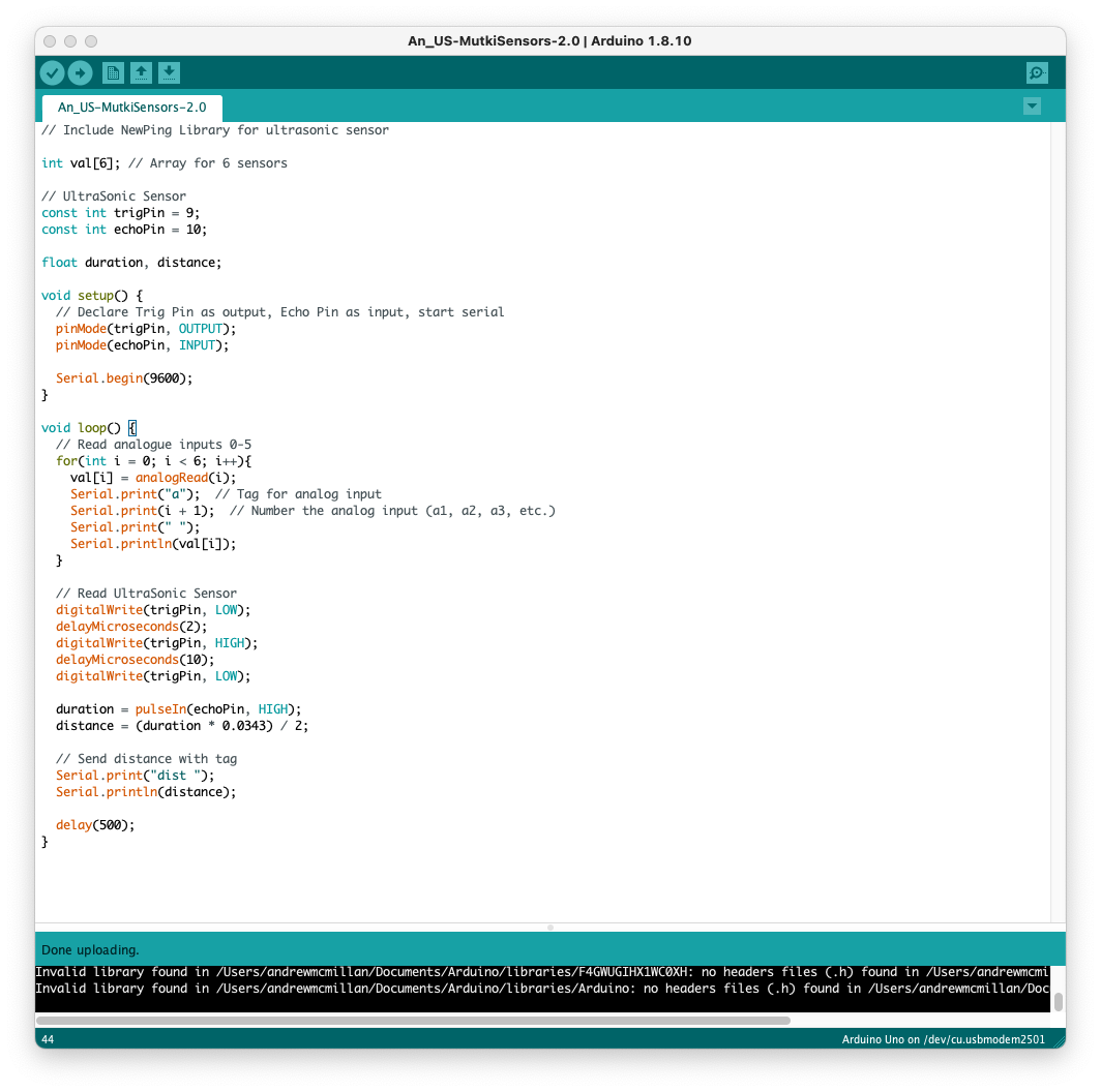 [sAp-Sensors Input Test.pd](/uploads/files/1729806028183-sap-sensors-input-test.pd) 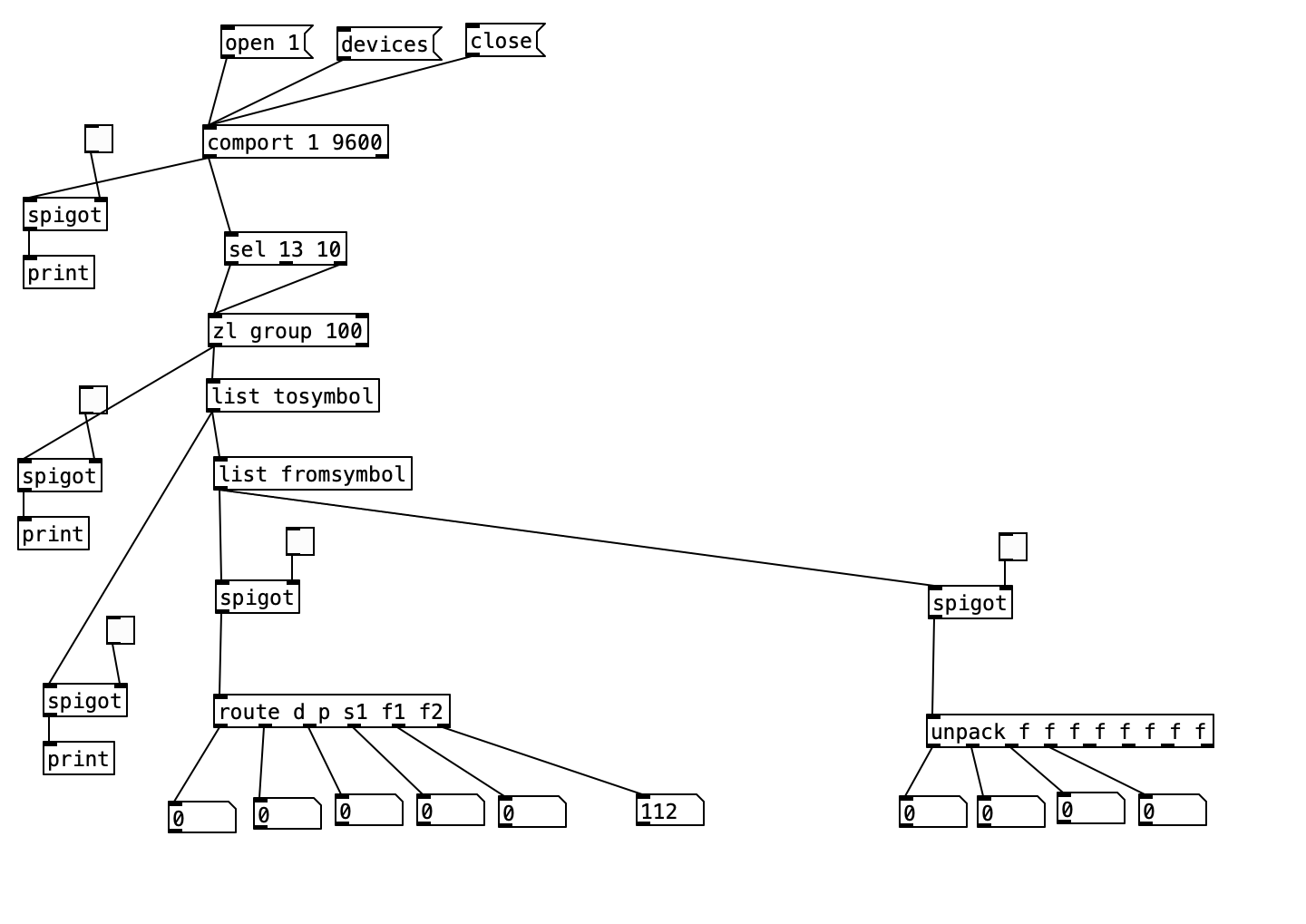 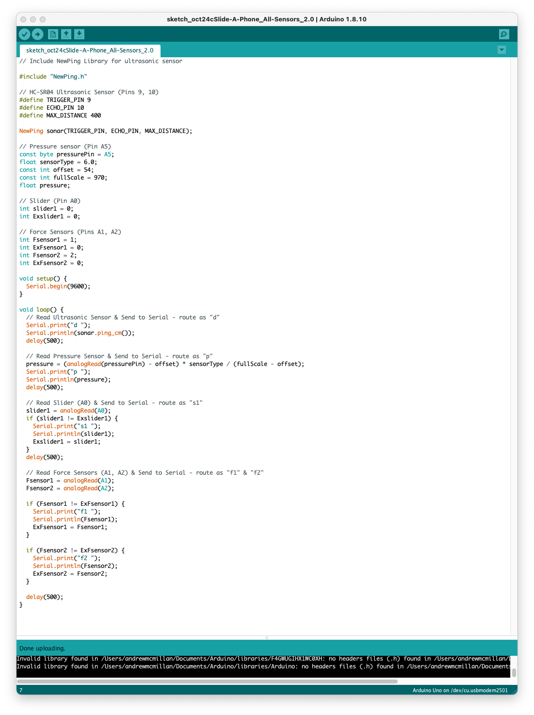
 posted in technical issues
Pd compiled for double-precision floats and Windows
@jameslo said:
@ddw_music I love that story but am scratching my head over the 1/10 example you gave. Here's a test I made in Arduino c++: ... I went out 40 digits and didn't see anything unexpected. Was that example you gave just a metaphor for the issue, or is my test naive?
Not a metaphor at all:
[16, 17, 40].do { |prec|
    "% digits: %\n".postf(
        prec,
        0.1.asStringPrec(prec)
    )
};

16 digits: 0.1
17 digits: 0.10000000000000001
40 digits: 0.1000000000000000055511151231257827021182
As for Arduino, the float datatype reference says "Unlike other platforms, where you can get more precision by using a double (e.g. up to 15 digits), on the Arduino, double is the same size as float" -- so my guess here is that Serial places a limit on the number of digits it will try to render, and then fills the rest with zeros.
I went out 40 digits and didn't see anything unexpected.
Seeing zeros all the way out to 40 digits is unexpected! Arduino's output here is more comforting to end-users (which might be why they did that), but it isn't accurate.
Considering that Arduino calculates "double" using single precision, the output should deviate from the mathematically true value even earlier:
// 0.1.as32Bits = single precision but as an integer
// Float.from32Bits = double precision but based on the 32 bit float
Float.from32Bits(0.1.as32Bits).asStringPrec(40)

-> 0.100000001490116119384765625
The most reasonable conclusion I can draw is that Arduino is gussying up the output to reduce the number of "what the xxx is it printing" questions on their forum. That should not be taken as a standard against which other software libraries may be judged.
Edit: hmm, but here's Pd64.
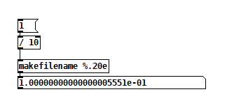
Pd64 is doing it right, and Arduino is not.
Getting back to how Pd seems to differ from other programming languages, I'm going to hazard a guess and say that Pd hasn't separated the value of a float from its display/storage format.
The value must be stored in standard single/double precision format. You need the CPU to be able to take advantage of floating point instructions.
It's rather that Pd has to render the arguments as text, and this part isn't syncing up with the "double" compiler switch.
PS I hope my attempt at humor didn't discourage @porres from responding to @oid's question. I'm sure he would have something more meaningful to contribute.
Of patchers as programming languages... well, I got a lot of opinions about that. Another time. For now, just to say, classical algorithms are much harder to express in patchers because patchers are missing a few key features of programming languages.
hjh
 posted in technical issues
Ultrasonic distance sensors with Pd in Bela
The ultrasonic distance sensors are usually digital, not analog. If this is the case, you're trying to read a digital signal as analog, which doesn't make much sense. This sensor has two pins, a trigger and an echo. You have to send a high voltage to the trigger pin, then pull it low, and read the echo pin which will help you compute the distance based on the time it took for this trigger pulse to arrive back at the echo pin.
The code below (copied from Arduino'g Project Hub), uses Arduino's pulseIn() function, to compute the distance:
// Define Trig and Echo pin:
#define trigPin 2
#define echoPin 3
//  Define variables:
long duration;
int distance;
void setup() {
  // Define  inputs and outputs:
  pinMode(trigPin, OUTPUT);
  pinMode(echoPin, INPUT);
  //Begin Serial communication at a baudrate of 9600:
  Serial.begin(9600);
}
void  loop() {
  digitalWrite(trigPin, LOW);
  delayMicroseconds(5);
  digitalWrite(trigPin,  HIGH);
  delayMicroseconds(10);
  digitalWrite(trigPin, LOW);
  // Read  the echoPin, pulseIn() returns the duration (length of the pulse) in microseconds:
  duration = pulseIn(echoPin, HIGH);
  // Calculate the distance:
  distance=  duration*0.034/2;
  // Print the distance on the Serial Monitor
  Serial.print("Distance  = ");
  Serial.print(distance);
  Serial.println(" cm");
  delay(1000);
}
I searched online and found the source of this pulseIn() function in Arduino's forum, which is this:
/*
  wiring_pulse.c - pulseIn() function
  Part of Arduino - http://www.arduino.cc/

  Copyright (c) 2005-2006 David A. Mellis

  This library is free software; you can redistribute it and/or
  modify it under the terms of the GNU Lesser General Public
  License as published by the Free Software Foundation; either
  version 2.1 of the License, or (at your option) any later version.

  This library is distributed in the hope that it will be useful,
  but WITHOUT ANY WARRANTY; without even the implied warranty of
  MERCHANTABILITY or FITNESS FOR A PARTICULAR PURPOSE.  See the GNU
  Lesser General Public License for more details.

  You should have received a copy of the GNU Lesser General
  Public License along with this library; if not, write to the
  Free Software Foundation, Inc., 59 Temple Place, Suite 330,
  Boston, MA  02111-1307  USA

  $Id: wiring.c 248 2007-02-03 15:36:30Z mellis $
*/

#include "wiring_private.h"
#include "pins_arduino.h"

/* Measures the length (in microseconds) of a pulse on the pin; state is HIGH
 * or LOW, the type of pulse to measure.  Works on pulses from 2-3 microseconds
 * to 3 minutes in length, but must be called at least a few dozen microseconds
 * before the start of the pulse. */
unsigned long pulseIn(uint8_t pin, uint8_t state, unsigned long timeout)
{
    // cache the port and bit of the pin in order to speed up the
    // pulse width measuring loop and achieve finer resolution.  calling
    // digitalRead() instead yields much coarser resolution.
    uint8_t bit = digitalPinToBitMask(pin);
    uint8_t port = digitalPinToPort(pin);
    uint8_t stateMask = (state ? bit : 0);
    unsigned long width = 0; // keep initialization out of time critical area

    // convert the timeout from microseconds to a number of times through
    // the initial loop; it takes 16 clock cycles per iteration.
    unsigned long numloops = 0;
    unsigned long maxloops = microsecondsToClockCycles(timeout) / 16;

    // wait for any previous pulse to end
    while ((*portInputRegister(port) & bit) == stateMask)
        if (numloops++ == maxloops)
            return 0;

    // wait for the pulse to start
    while ((*portInputRegister(port) & bit) != stateMask)
        if (numloops++ == maxloops)
            return 0;

    // wait for the pulse to stop
    while ((*portInputRegister(port) & bit) == stateMask) {
        if (numloops++ == maxloops)
            return 0;
        width++;
    }

    // convert the reading to microseconds. The loop has been determined
    // to be 20 clock cycles long and have about 16 clocks between the edge
    // and the start of the loop. There will be some error introduced by
    // the interrupt handlers.
    return clockCyclesToMicroseconds(width * 21 + 16);
}
This is already getting complicated, as pulseIn() uses other functions which should be found and translated to Pd. I guess the best thing you can do is try to translate the first code chuck in this reply to Pd, and when you read a high voltage in the echo pin, do some math to calculate the distance.
In essence, set a digital input and a digital output pin on the Bela, trigger the output pin with a high and low signal, and keep reading the input pin (you should probably use a pull-down resistor there), until you get a high. Calculate the time it took with the [timer] object and do some simple math to get the distance. Do that with distances you know first, and then use the rule of three based on the known distance and the time you get. At least, that's how I would try to get this to work.
Another solution is to use an infrared proximity sensor, which is analog, and it's probably much easier to use. But this gets the proximity of obstacles right in front of it only, while the ultrasonic range finder has a wider field where it can detect obstacles.
 posted in technical issues
comport (couldn't create / can't load abstraction within itself)
Hello all,
Looking for some help with the comport object, it has suddenly stopped working.
When I try to create the object I get the error:
comport
... couldn't create
comport: can't load abstraction within itself
I have updated PD, deleted comport within the externals, then reinstalled it using help>find externals within PD and still get the same error - any ideas? I have also tried using "declare" to no effect.
When I open the "comport-help.pd", "comport-meta.pd" and "comport-stress-test" within the externals>comport folder all comport objects are greyed out... Trying to get PD to talk with Arduino... Thanks!
 posted in technical issues
Arduino -> Pduino problem measuring lapsed time with [realtime]
Great input all of it, thanks!
@whale-av said:
@AndreasA You could probably round your data...... as you are always close to an integer (no 2 3 4 5 6 or 7).....
[expr int (0.5 + $f1) ]
.... maybe a [/ 10] first and a [* 10] after for the data we see....... but of course that is for a particular speed..... so maybe not?
You could also set a window large enough to accept changes as the speed varies, but filter numbers that are out of range (those around 20 in this case... or is it those around 10?) and reject them.
Yeah well didn’t give you enough information there. These numbers I get is at maximum speed of my wheel, or rather the lowest number that pd will output when over a certain speed. So I want it to be able to handle that and all slower speeds as well. The [smooth] is awesome, thanks for the tip!
@jameslo said:
@AndreasA I'm assuming that the numbers you are seeing in the Arduino IDE are timings you captured on the Arduino, not using [realtime], is that correct? If so I think @alexandros is suggesting that you send those timings to Pd, instead of trying to measure the times between Arduino messages on the Pd side.
Actually discovered some problems on the Arduino-side as well so I actually had both arduino and pd limit the output there for a while. But arduino is now definitely taken care of. With @alexandros method I’m closer to what I want but not quite there. Thinking about lowering the bar and deal with it as a limitation later on in the actual synth.
The thing with [realtime] was really interesting read. Good stuff to know!
Though, it would be awesome to have the resolution of serial_print but with firmata and pduino. Pduino is such a great interface for someone not use to coding and I’d like to add more sensors on the same arduino, which right now feels like a big undertaken without pduino and with my lack of knowledge.
Is there a way, do you think? Could I mess with the firmata code to add serial.print()? Obviously wrong forum, but just in case someone has tried.
 posted in technical issues
PIR+ARDUINO+PDUINO
@je You are missing (at least - there might be other things) the port number for [comport].
In arduino.pd you will see the object [comport $1 57600]
When an object has a dollar argument like that the $1 will become the value of the first argument of the patch that contains the object.... as that patch is opened (we say "created" as Pd builds all the connections and does such substitutions as the patch is opened).
It is not the same in a message - dollar signs behave differently in a message - https://forum.pdpatchrepo.info/topic/9774/pure-data-noob/4
So in PIR_Arduino_Puredata V2.pd you need to give the argument a value which means changing the object [arduino] to [arduino 1] if the port to open is 1..... or [arduino 7] if using port 7.
To repeat myself.... the 1 will then replace the $1 in [comport $1 57600] ..... as the patch opens it will become [comport 1 57600] ...... even though you still see the $1 on the screen.
David.
 posted in I/O hardware diy
PIR+ARDUINO+PDUINO
Jumping in due to David's prompt. I don't use PDuino, but I checked both yours and David's version of your patch, and there's no [arduino] or [comport] object. So, how do you expect to communicate with the Arduino using Firmata, since you don't have these two? [comport] is used for serial communication with USB devices, and [arduino] takes care to translate the user-friendly messages, such as "pinMode 2 input" to bytes in the Firmata protocol. I think the [arduino] abstraction includes the [comport] object, so it takes care of that for you.
From what I understand, you have to send this "pinMode" message to the [arduino] abstraction, and you'll receive some output from it. Connect a [print] to it to see what you get.
posted in I/O hardware diy
[catch~]: Would like to set the name programmatically
@ingox said:
latency-tester right,
it's not. here some fixes:
[throw~] and [catch~] do bring some latency with them as far as i know...
It depends on the execution order, described in 3. G05 of Pd documentation.
Patching like this has no latency for your 2nd and 3d version, as for dyncatch~ and throw~ chatch~ and s~ r~.
But there is other trouble with the 2nd and 3d version:
Deleting by 'dynamic-mouse-clicks' doesn't work if I use Pd's zoom-in, as I usaually do.
This is a bug of Pd: it messes up the coordinates.
Same happens if I undo after moving an object, it reappears somewhere else...
@ddw_music said:
In SC, I can arrange mixer channels in the order source --> target
[...] looks like the only way to force order is using an explicit patch cable
Not sure, but I belive only the order of objects is important, and even msend~ v1 could have 0 latency, if it would care about creation order!? Even across multiple patches? Creation order = execution order ?
Edit: yes and no: it's the creation order of the whole chain ...
in latency-tester2.pd:
[pd latency-meter] is the first object, [pd click] comes later,
... so deleting the patch-cord between [pd s] [pd r] brings back block-latency.
 posted in technical issues
Having lots of switches into Pd
Thank you for replying and sorry if I am unclear. I will try to slow down a bit.
@alexandros said:
@cfry definitely not necessary to use two Arduinos. I can't really understand where your problem lies.
-The problem is that it does not work when I try to use an arbitrary combination of pins in different modes (Digital in, Digital out, Analog in, Analog out).
Another problem is that I have a hard time reading the code parts that are handling the conversion data in order to do the serial communication, although I understand the principle of it.
You didn't reply to my earlier question about the pinMode calls where you use INPUT_PULLUP on analog inputs. Is this really necessary?
-I assumed that the problem lied in void ()loop as a conflict between the output and input handling sections. And that pinMode calls in void setup() was not relevant in this case. That is why I did not answer that question directly.
Also, why not use the analog pins in an array like with the digital pins? It will save a lot of writing and it's less error prone.
-I was foreseeing that I may want to configure those pins individually, but I can set it up with a loop for now.
One thing you might want to consider is having the Arduino notify Pd when it's done sending all its data and that it's ready to receive. That could be done at the end of the loop() function like this:
Serial.print("done ");
Serial.println("bang");
And in Pd have a [r done] object which will output a bang. Use this bang to send data from Pd to the Arduino by unpacking a list with all the accumulated data, possibly with a [list-abs/list-drip].
I use this notification technique in my 3dPdModular system, but there's a LOT of data there and it was only necessary. Perhaps you could try it out.
-I will try that.
Since I consider this to be basically your code I assumed that you could easily just insert the code for both input and output in void loop() in a way that works and that would show me how to solve it. Then I would be able to do further explorations and it would be end of story.
I will digest this a bit and may start a new thread, since this one has slided from "Having lots of switches into Pd" to "having a working code template for communicating between Arduino and Pd using and an arbitrary mixture of pin modes".
Please let me know if this still does not make sense. Thank you so much!
 posted in I/O hardware diy