abl_link~ maintenance?
@jancsika said:
Where is the specification for ableton link?
Relevant bit is: https://github.com/Ableton/link#latency-compensation
"In order for multiple devices to play in time, we need to synchronize the moment at which their signals hit the speaker or output cable. If this compensation is not performed, the output signals from devices with different output latencies will exhibit a persistent offset from each other. For this reason, the audio system's output latency should be added to system time values before passing them to Link methods."
abl_link~, by default, doesn't do this. But, at https://github.com/libpd/abl_link/issues/20, I was told that [abl_link~] response to a "offset $1" message where a positive number of milliseconds pushes the timing messages earlier.
Using that, it's actually easy to tune manually.
This was undocumented -- intentionally undocumented, for a reason that I can't say I agree with. So I'll put in a PR to document it.
Also-- Assuming that arbitrary devices are to be able to connect through ableton link, I don't see how there could be any solution to the design of abl_link that doesn't require a human user to choose an offset based on measuring round-trip latency the given arbitrary device/configuration. You either have to do that or have everyone on high end audio interfaces (or perhaps homogenous devices like all iphones or something).
As far as I know (and I haven't gone deeply into Link's sources), Link establishes a relationship between the local machine's system time and a shared timebase that is synchronized over the network. Exactly how the shared timebase is synchronized, I couldn't tell you in detail, but linear regressions and Kalman filters are involved -- so I imagine it could make a prediction, based on the last n beats, of the system time when beat 243.5 is supposed to happen, and adjust the prediction by small amounts, incrementally, to keep all the players together.
Then, as quoted above, it stipulates that the sound for beat 243.5 should hit the speakers at the system time associated with that beat. The client app knows what time it is, and knows the audio driver latency, and that's enough.
So, imagine one machine running one application on one soundcard with a 256 sample hardware buffer and another app on a different soundcard with a 2048 sample hardware buffer. The system times will be the same. If both apps compensate for audio driver latency, then they play together -- and because the driver latency figure is provided by the driver, the user doesn't have to configure it manually.
The genius of Link is that they got system times (which you can't assume to be the same on multiple machines) to line up closely enough for musical usage. Sounds impossible, but they have actually done it.
Put another way-- if you can figure out an automated way to tackle this problem for arbitrary Linux configurations/devices, please abstract out that solution into a library that will be the most useful addition to Linux audio in decades.
Ableton Link actually is that library.
https://github.com/Ableton/link/blob/master/include/ableton/Link.hpp#L5-L9
license:
This program is free software: you can redistribute it and/or modify
it under the terms of the GNU General Public License as published by
the Free Software Foundation, either version 2 of the License, or
(at your option) any later version.
 posted in extra~
Pduino problem
just tested what you uploaded, got this:
netreceive: failed to sett SO_BROADCAST
arduino 1
... couldn't create
and nothing else. i dont get unknown input command msgs anymore, even after setting the proper port and arduino analog pin. im on Win 7 Professional.
now, i moved the moocow folder you attached to my original pd patch folder and got this:
netreceive: failed to sett SO_BROADCAST
comport - PD external for unix/windows
LGPL 1998-2015, Winfried Ritsch and others (see LICENSE.txt)
Institute for Electronic Music - Graz
[comport] Opening COM1
[comport]: could not open device COM1:
failure(2) ERROR_FILE_NOT_FOUND
[comport] opening serial port 1 failed!
route 13 0 20 1 (message->prepend) connection failed
route 14 0 20 1 (message->prepend) connection failed
route 16 0 20 1 (bang->prepend) connection failed
route 17 0 20 1 (bang->prepend) connection failed
[arduino]: version_0.5
[comport]: could not open device COM1:
failure(2) ERROR_FILE_NOT_FOUND
Firmware: StandardFirmata.ino-2.5
UNKNOWN_INPUT_COMMAND: 0 240
UNKNOWN_INPUT_COMMAND: 0 239
UNKNOWN_INPUT_COMMAND: 0 239
UNKNOWN_INPUT_COMMAND: 0 239
UNKNOWN_INPUT_COMMAND: 0 239
UNKNOWN_INPUT_COMMAND: 0 239
UNKNOWN_INPUT_COMMAND: 0 239
UNKNOWN_INPUT_COMMAND: 0 239
UNKNOWN_INPUT_COMMAND: 0 239
no more moocow errors anymore, then i set the port, got the firmata 2.5 message, then set pin a0 and got the endless stream of unknown input command msgs that change value when i move the pot. i think we're pretty close, but still not there :/
 posted in technical issues
Pduino problem
Hello everyone, ive got this problem while trying to connect my arduino to Pd. Already installed firmata, used firmata test app to check its ok, and it is. But when i open the arduino-test pd patch, i get this:
netreceive: failed to sett SO_BROADCAST
comport - PD external for unix/windows
LGPL 1998-2015, Winfried Ritsch and others (see LICENSE.txt)
Institute for Electronic Music - Graz
[comport] Opening COM1
[comport]: could not open device COM1:
failure(2) ERROR_FILE_NOT_FOUND
[comport] opening serial port 1 failed!
moocow/string2any 32 -1
... couldn't create
route 13 0 20 1 (message->prepend) connection failed
route 14 0 20 1 (message->prepend) connection failed
route 16 0 20 1 (bang->prepend) connection failed
route 17 0 20 1 (bang->prepend) connection failed
moocow/string2any 32 -1
... couldn't create
moocow/any2string
... couldn't create
moocow/any2string
... couldn't create
moocow/string2any 32 -1
... couldn't create
[arduino]: version_0.5
[comport]: could not open device COM1:
failure(2) ERROR_FILE_NOT_FOUND
Firmware: 2-5.
UNKNOWN_INPUT_COMMAND: 0 480
UNKNOWN_INPUT_COMMAND: 0 479
UNKNOWN_INPUT_COMMAND: 0 479
UNKNOWN_INPUT_COMMAND: 0 480
UNKNOWN_INPUT_COMMAND: 0 479
UNKNOWN_INPUT_COMMAND: 0 480
UNKNOWN_INPUT_COMMAND: 0 479
UNKNOWN_INPUT_COMMAND: 0 479
UNKNOWN_INPUT_COMMAND: 0 479
UNKNOWN_INPUT_COMMAND: 0 480
UNKNOWN_INPUT_COMMAND: 0 479
UNKNOWN_INPUT_COMMAND: 0 480
So, i select the port im using and the A0 pin which is the one with the potentiometer im gonna use, and i get thousands of UNKNOWN_INPUT_COMMAND messages, i turn the pot and the values go from 0 to 1000, and the pd device info block has Firmata 2.5 so its recognizing the device, but cant go beyond that. Any ideas? I see that moocow is missing (and that could be relevant), but couldnt get anything using the "find externals" function.
posted in technical issues
pduino for Vanilla or how to control arduino outputs from PD
[arduino] is the Pduino abstraction that communicates with Arduino via Firmata, and I think it's vanilla. Any way, if all you want is to control Arduino pins from Pd, you just need to send the correct bytes to Arduino through [comport].
I've written a tutorial on the communication between Pd and Arduino which you can find here, under "Tutorials", it's called "Arduino for Pd'ers".
After I wrote the tutorial I also wrote some abstractions to facilitate this communication, which are not used in the tutorial. You can get them here. Though, these are meant to receive data from the Arduino, not send. Sending data is covered in the tutorial.
 posted in technical issues
Digital to audio processing issues
@Joseph-Mikkelson No, changing the samplerate will not help, except that matching it to the soundcard reduces the load on the cpu......but there are more important issues...... see below.....
I should have expanded on latency.
Using a live input [adc~] and doing some Pd processing effects and then sending that to speakers [dac~] latency is not so much of a problem. Often it involves delays anyway (echo, reverb, etc.) and our ears are used to that.
Latency for playback of an audio track, or generated audio, is no problem...... it is heard when it arrives at the speakers and that is all.
Problems arise when the input goes straight to the output....... as with a monitor mixer built in Pd for example..... with live acoustic instruments...... where the musician hears their own instrument acoustically and the same sound delayed in the monitor. Essentially a chorus effect is produced, caused by the latency, and that will make it harder for a violinist for example to pitch correctly.
Chorus in a reverb effect really upsets violinists..... anything much over 5ms.
Of course a massive latency...... 100ms+..... will cause timing problems even for a guitarist, and even if they are the rare musician that didn't have such issues in the first place.
I have met classical and jazz musicians that have learnt to dissociate what they play from what they hear...... for example playing through a delay, but in sync with everyone else...... so playing say 1 second before everyone else....... but...... 
SAMPLE RATE
You should match your samplerate to your soundcard, or you will have re-sampling artefacts....... usually a low level high pitched whine when your patch is not producing any sound.
It is slightly more complicated than that.
If you play an audio file that was recorded at 44.1KHz while the Pd samplerate is set to 48KHz it will play back at the wrong speed....... Pd will not resample it and so the pitch will be wrong.
It's a PITA.
So the Pd samplerate must be set to match all the audio files that you use in Pd.
To avoid the artefacts you then need to set your soundcard to match Pd.
Other programs will adjust..... so that is not a problem.
External cards can make that change through their control panel, and internal cards should have the option somewhere.
In windows it is here in the speaker control panel..... https://forum.pdpatchrepo.info/topic/12094/newbie-clipping-on-pure-data-portable-with-mmio/4
and I am pretty sure that windows always sets the on-board soundcard to 48KHz "out of the box".
David.
 posted in technical issues
Build a MIDI controller with the Arduino, Firmata and Pure Data
Time to start contributing some knowledge back to the wonderful world that is the internet; today, a step by step nice and easy tutorial on getting started to building your own MIDI controllers with the arduino.
When researching for my ableton controller project, I didn’t find much out there about using firmata on an arduino to send data to software. The standard approach just seemed to be create the code in the arduino language, upload it to your board and hack one of those MIDI to USB cables as a bodge job way of getting the MIDI out of the arduino.
So why firmata and pure data? Well the whole idea of firmata is that you flash it to your arduino, and it throws out serial about whats going on with the arduino inputs and outputs, then you decide how the software treats the readings coming in and going out.
Theory out the way, lets build some controllers. You’ll need a few things…
HARDWARE:
An arduino and something to wire into it (for this i’ll be using a pot)
A USB cable for your arduino
SOFTWARE:
Arduino – http://arduino.cc/en/Main/Software
Pure Data – http://puredata.info/downloads
Firmata – http://at.or.at/hans/pd/objects.html#pduino
Something to patch your new controller into; like Reason or Ableton Live
- SETTING UP FIRMATA AND PURE DATA
Install Pure Data and create a folder to store all your patches somewhere. Unzip Firmata and add the files ‘arduino.pd’, ‘arduino-test.pd’ and ‘arduino-help.pd’ to your new Pure Data folder. The ‘arduino.pd’ file is the object that we use in PD for opening up communication with your arduino and routing it to PD. Done? Awesome, your software is almost set up.
- FLASHING FIRMATA TO YOUR ARDUINO
Install the latest version of arduino and open it up. Connect your arduino with the USB cable to your laptop (i’m using a macbook for this by the way). In the example patches, open up “Standard Firmata”, select your board (im using an arduino mega), and your serial port (look for tty.usbserial for use with a USB cable). Then compile and hit the upload button and your arduino is now ready to use firmata and communicate with Pure Data!
- WIRING UP A POT
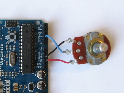
Potentiometers are cool, and theres a great arduino tutorial of how to wire one up here: http://www.arduino.cc/en/Tutorial/Potentiometer
Basically, all you need to know is that there are three pins; your two outer pins govern voltage flow across the pot, meaning one has to be 5V and the other has to be ground. It doesn’t matter which, but your 5v pin is going to be where your pot reads maximum, so convention dictates this should be the right hand pin. The center pin needs to be connected to an analog in on the arduino and will read the value of the pot as it sweeps from ground (0v) to 5v.
All wired up? Plug it into your laptop and open Pure Data, we’re ready to get things talking.
- SETTING UP OUR PATCH
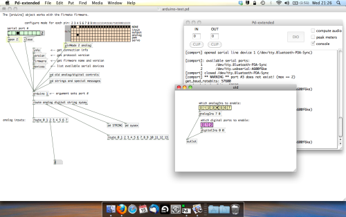
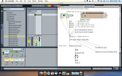
Open the example “arduino-test.pd” Pure Data patch you copied over earlier. It should look like this one…
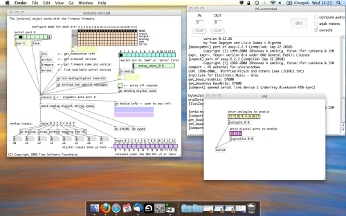
The test patch has everything we need to open a connection and enable pins. Firstly, lets delete a bunch of stuff and make our window a bit bigger. Hit Command + E to enter edit mode in Pure Data.
Ok a quick explaination; the key component here is the ‘arduino’ object. This is being drawn from the file you copied in earlier, and is what communicated with your arduino. Here we can do everything to control the arduino from opening a connection, to receiving data.
The large grid allows us to set the mode of each pin on the arduino. Remember pins 0 and 1 are reserved for Rx and Tx. I’m using analog pin 4 for this demo, so I’ve set my pin mode for pin 4 to ‘analog’.
Now we can plug our arduino in and get a reading from the potentiometer.
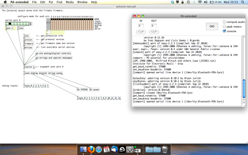
- ARDUINO INTO PURE DATA
With your arduino plugged in, hit command and E to bring us out of edit mode. In our patch, click on ‘Devices’ above the arduino object and open up the pure data terminal. (That other thing that loads with PD that has all the scary code in)
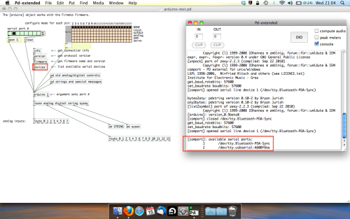
The “Devices” message connected to the arduino object pings your computer to find what devices are connected and on what serial ports. Since we’re using a USB cable to connect our arduino, we’re looking for something with ‘usbserial’ in it, in this case; port 2.
Select the relevent port in the green box at the top (remember the first box is ‘0’, second is ‘1’ and so forth) and hit ‘Open’ to establish a connection. Check the terminal to see if the connection was sucessful.

Now lets check we’re getting something in. Create a number box (Command + 3) and connect it to the relevent pin on the ‘Route analog’ box at the bottom. In this case, pin 4.
One more thing; if you’re not getting any readings in, you’ll need to click on ‘pd old analog/digital controls’ and enable your pins here too. What I tend to do in my patches is just not include the large grid but make my own ‘old pd’ controls custom to what i’m enabling/disabling to save space.
Here’s what the ‘old analog/digital controls’ subpatch looks like (pin 4 enabled)…
Come out of edit mode and check that you’ve got readings. If so congratulations! If not, troubleshoot, start with making sure your usb connection is opened, make sure all the correct pins are enabled (remember you’re counting from 0 not 1 on most of these buttons in PD, it’s just the way computers work).
- SCALING READINGS TO MIDI
So we’ve got a reading and chances are it’s to 3 decimal places between 0 to 1. No problem, create a new object (Command + 1) and type “autoscale 0 127”. This allows us to scale the input to a min and max value, in this case 0 to 127 of MIDI. Next, lets get things looking nice, create a new object and type “knob”. Connect this AFTER the autoscale object. (the knob is default set to read inputs from 0 to 127. Then create another number to display the scaled MIDI data coming out, and finally a new object and type “ctlout 1”.
It should look something like this…
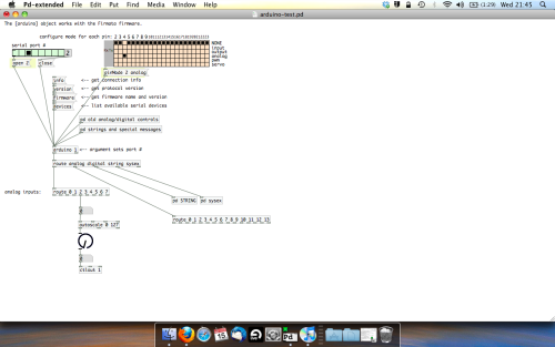
The second box should be outputing values from 0 – 127 now, and the knob giving a visual representation of your potentiometer.
Now lets patch it into ableton…
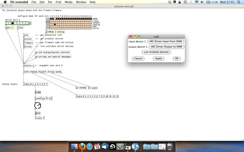
- PURE DATA TO ABLETON LIVE
Firstly, you’ll need to set up your macs IAC driver if you’ve not done this. Basically you’ll need to go into Audio/MIDI preferences and enable your IAC driver. Then create a new input and output. One for input to DAW and one for output from DAW. Google around for a tutorial on this, its really simple, a 30 second job.
After you’ve set up your IAC driver, go back to PD and go to preferences > MIDI Settings, and connect your IAC driver.
Open ableton and go to its MIDI preferences. Create a device listing for your IAC driver and enable its ins and outs into ableton like so…
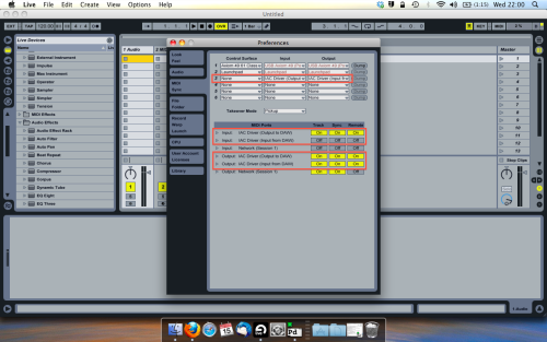
And thats it! Create an instrument and try to assign something! I’ve got it controlling the brightness of a bass sound here.
Shout out for Facu who requested this tutorial. Hopefully it’ll help some of you looking to get into this stuff and start building things but with no idea where to start.
 posted in tutorials
Pduino + Arduino Output to Pins
Dear Forum,
Experienced PD user, intermediate Arduino user here.
My goal is to send several different frequency square waves (to be used as "on" and "off" signals for a circuit) to various output pins on an Arduino.
I am up and running using the Pduino library, and have PD and Arduino talking to each other.
However, I am not able to output audio-rate signals to any Arduino pins. For example, sending a square~ into an appropriately timed snapshot~ to output 0's and 1's to Arduino pins yields random clicking/sputtering Arduino output, rather than the expected steady square wave tone at any freq.
My arduinos play a square wave out through the pins just fine when using the Arduino IDE...so, what am I missing in the communication between Arduino and PD/Pduino? A speed issue?
Thanks in advance for any advice!
 posted in technical issues
Some questions regarding a loop station
@whale-av
I'm using a RME Fireface uc with it's own Asio driver on Win7/10. On Purr Data or vanilla I can set latency to 2 ms as well, but the roundtrip latency tester gives me the same results for 2-5 ms (around 440 samples measured with cable). With a 48 sample buffer instead of 64 on my soundcard I receive even worse values.
But on pd-extended it just doesn't work. Don't know why, but as it's not updated anymore, I prefer working with vanilla and Purr Data.
Anyway - in the manner I'm trying to loop, latency doesn't really matter, but you have to know it's length. Even with a latency of 50 ms or more you won't notice any offset in the recorded loops as long as you know the exact length of the latency.
Tracks get recorded and shifted by the latency afterwards, so latency should be compensated.
You're right, latency won't add up in Pd. But I don't use an in ear system. So if you change your reference from a metronom to a recorded track and from that track to the next recorded one, you will add up latency when the latency isn't compensated.
Xaver
 posted in technical issues
Some questions regarding a loop station
I changed my first post and uploaded a zip at the end.
Works with Purr Data or pd (plus zexy)
@whale-av
Thanks for your patch. I tested it with extended, but I get latency issues. When I record saying something like "tik" on the beat, the "tik" is heavily delayed to the metronom on playback. But on pd extended I can't set the latency lower than 24 msecs. So there might be some issues with extendend on my machine. (pd or Purr Data let me set the latency to 5 msecs without problems.)
You wrote: The biggest problem with (not noticing) an edit will be a difference of volume (power). Our ears are very sensitive to that.
The second biggest problem will be the quality.... timbre..... but as you say a crossfade could help. But the bigger the difference the longer the crossfade needs to be.
I thought about starting recording a little bit earlier and stop somewhat later, so I can crossfade between these extra samples. And maybe it's easier than I thought.
@LiamG
Thanks. How can I trigger between blocks? I thought messages are only send once during a block, aren't they?
About 3): I was wondering, if it is a problem, not to be able to set the exact metronom tempo
And here's a little screenshot to see what it looks like:
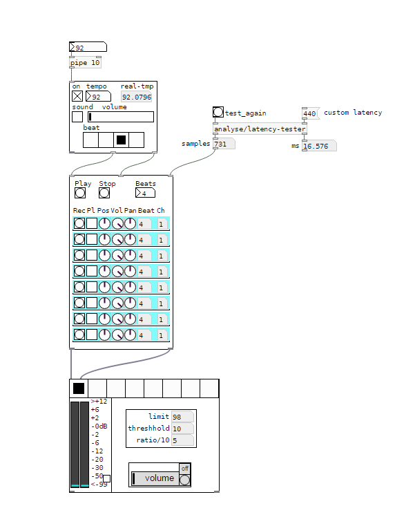
I would say, anything above 5 ms latency between the metronom and some voices starts to feel strange. And when you start to change your reference - say you start recording with the metronom, change to first recorded line as a reference, than to the second etc, - the latency will sum up and increase.
I wonder how latency is treated on hardware loop stations.
And I'm still asking myself how latency should be treated to get it right.
Regards,
Xaver
posted in technical issues
Problem with [comport]
Hello
i have one problem and i don't know how to solve it without going back to windows 8.1
before i update my pc to windows 10 my puredata+arduino work, on arduino i use Serial.write(); to comunicate with puredata with [comport 9600] but now when i open puredata sketch i get this error:
comport number 9600 out of range (1-99)
[comport] opening serial port 9600 failed!
comport number 9600 out of range (1-99)
[comport] opening serial port 9600 failed!
and when i try to open port 3 (where i have arduino connected) i get this error:
Opening COM3
[comport] opened serial line device 3 (COM3)
[comport]: RXERRORS on serial line (997)
[comport]: RXERRORS on serial line (997)
[comport]: RXERRORS on serial line (997)
[comport]: RXERRORS on serial line (997)
[comport]: RXERRORS on serial line (997)
[comport]: RXERRORS on serial line (997)
[comport]: RXERRORS on serial line (997)
[comport]: RXERRORS on serial line (997)
[comport]: RXERRORS on serial line (997)
[comport]: RXERRORS on serial line (997)
and i can't receive the data from arduino.
I am using arduino 1.6.4 and puredata 0.43.4- extended
anyone can help me?
thanks in advance
 posted in technical issues