simple polyphonic synth - clone the central phasor or not?
@manuels That's clever, thanks! I especially like how you get the slope of the input phasor (compensating for that downward jump every cycle) and how you construct the output phasor. But I think there are two issues with it. Firstly, a sync will reset the phase of the output phasor at an arbitrary point unless the output phasor frequency is an exact multiple of the input frequency. Secondly, without sync, I think the output phasor may drift WRT the input phasor due to floating point roundoff error. Agree?
Backing out to look at the big picture again, i.e. Brendan's question, this means that it couldn't be used to make either a "hardsync" synthesizer (disclaimer: I don't really know what that is) or a "phasor~-synchronized system", assuming that both require a precise phase relationship between the input and output phasors and that the output phasor doesn't contain discontinuities. What do you think?
 posted in technical issues
using 0..10hz osc~ as amplitude modulation, when i get to 0, there's an audible click
@esaruoho when it gets to 0 frequency, use a [line~] going into the same inlet as the osc~ and ramp from
0 to the difference between the output value at the phase you want to set and the current output value (get w/ [snapshot~]). (so if current output of the osc~ is -0.25 and will be 1 when the phase gets set, ramp from 0 to 1,25).
then after the ramp is done, set the osc~ phase and reset the line~ to 0 at the same time.
this technique is called 'switch and ramp' and is explained by miller in his book http://msp.ucsd.edu/techniques/v0.11/book-html/node63.html
(here I did it in reverse by ramping first and then switching, but you could also simply add the discontinuity when you change the phase and ramp to 0. that would work to eliminate the discontinuity as well, but in that case the artifact might be more prominent bc the frequency is higher)
 posted in technical issues
using 0..10hz osc~ as amplitude modulation, when i get to 0, there's an audible click
@whale-av said:
@esaruoho The image is not useful as you say.
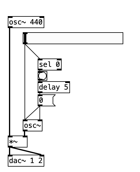
The only [osc~] that I see seems to be set to 0Hz and have its phase reset 5ms after receiving data..... so maybe the phase reset causes the click as the [osc~] wave could be at any value when the phase is reset and a sudden jump in value is a click.
David.
yep, that's what's happening. if i don't have the delay5 0( then the amplitude might be set to anything, so then i have to keep resetting it to zero multiple times until it's at the original volume. so hence the phase needs to be reset to 0.
here, maybe this'll help.
clicks when goes to 0.pd
i tried both hooking the 0..10hz osc to the first inlet of [*~] or the second inlet. both "goes to 0" result in an audible click.
how does one reset the phase so that the volume is at the original volume, please?
here's the attached script as a screenshot
 posted in technical issues
Controlling ramp time
Hi all, beginner here.
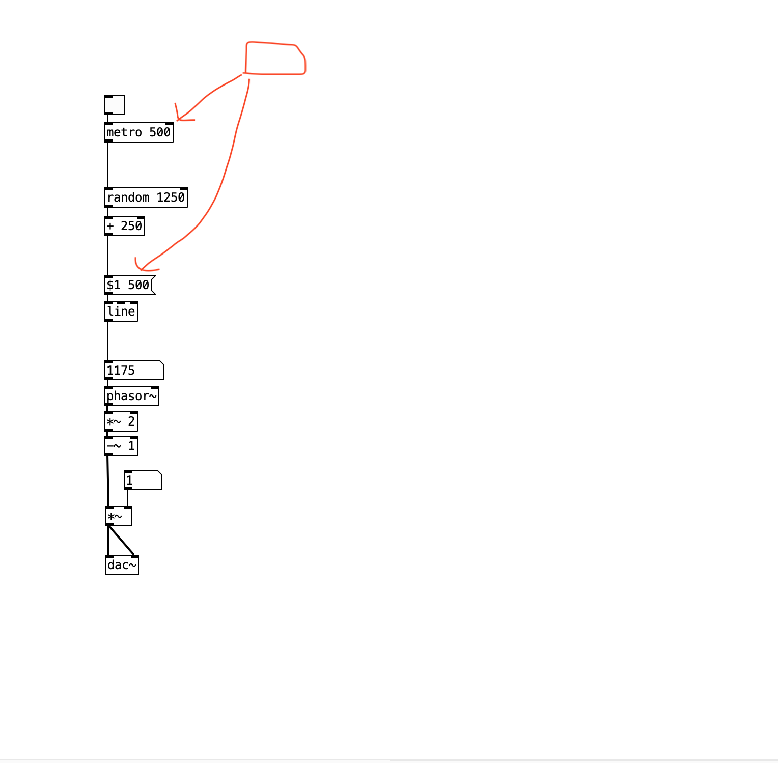
I'm trying to find a way to simultaneously modulate my METRO time and the ramp time of my LINE. I tried to crudely illustrate that concept in the red line drawing on my patch.
What I have here is
- METRO sends regular pulses to RANDOM
- with each pulse RANDOM chooses a random value
- values ramp from one to the next via LINE
- LINE passes values to NUMBER
- NUMBER passes values to PHASOR~ as frequency values
I want to be able to use one control that overrides the METRO time with a value that simultaneously becomes my LINE's ramp time. So when METRO is 1000ms, LINE ramp time is also 1000ms; when METRO is 750ms, LINE ramp time is also 750ms, etc.
Any insights on how to patch this up? Thank you!
 posted in technical issues
maths regarding conversion from metro speed to pitch
Another approach is to design the implementation around the requirement.
You want to be able to produce a specific frequency. So... make frequency the input parameter, rather than metro time interval.
You want to step through array values, with an equal amount of time for each. That suggests a linear ramp, with a given frequency... i.e., phasor~.
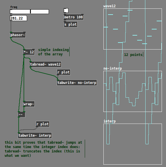
phasor~ always goes 0.0 - 1.0. With 12 points, the array indices go 0.0 - 11 -- but here, note that if you say 0.0 - 11.0, then index 0 covers a span of 1, but index 11 covers a span of 0! That doesn't sound right. Instead, define the span for each index as i <= x < (i+1) -- inclusive at the bottom, exclusive at the top. Now the entire range is 0 <= x < 12... leading to the idea of multiplying the phasor by 12 (number of points).
The array indexing should truncate away any fractional part: if (phasor * 12) = 3.546, it should just read 3. Fortunately, this is the normal behavior of tabread~ (not tabread4~).
So we can get a sample-and-hold waveform this way. (The third array is just showing the floor-ed indices, to demonstrate that tabread~ really is truncating rather than rounding.)
All that's left is to add linear interpolation. A standard way to do linear interpolation is:
x = crossfade factor (0.0 - 1.0)
a = value when x = 0
b = value when x = 1
xfade = (b-a) * x + a (this is a reduction of (a * (1-x)) + (b * x)).
If i is the index, then a = array "at" i, and b = array "at" i+1 -- but here, b needs to be modulo-wrapped back around, because i+1 could be 12-point-something. Pd vanilla doesn't have [%~] at signal rate, but [expr~] has fmod().
So we can index the two values, subtract, multiply by the crossfade factor (which is phasor * 12 --> wrap~), then add the "array[i]" value back in.
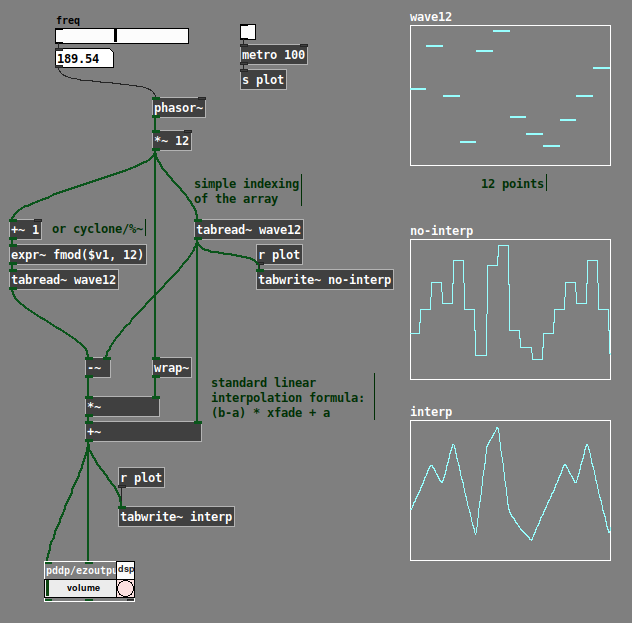
Now you can do whatever frequency you want, without the awkward conversion. Doesn't matter what that online tutorial said, IMO this fits the stated requirement better.
hjh
 posted in technical issues
Puzzling question about sqrt ~
Now I'v got it ..( I hope )
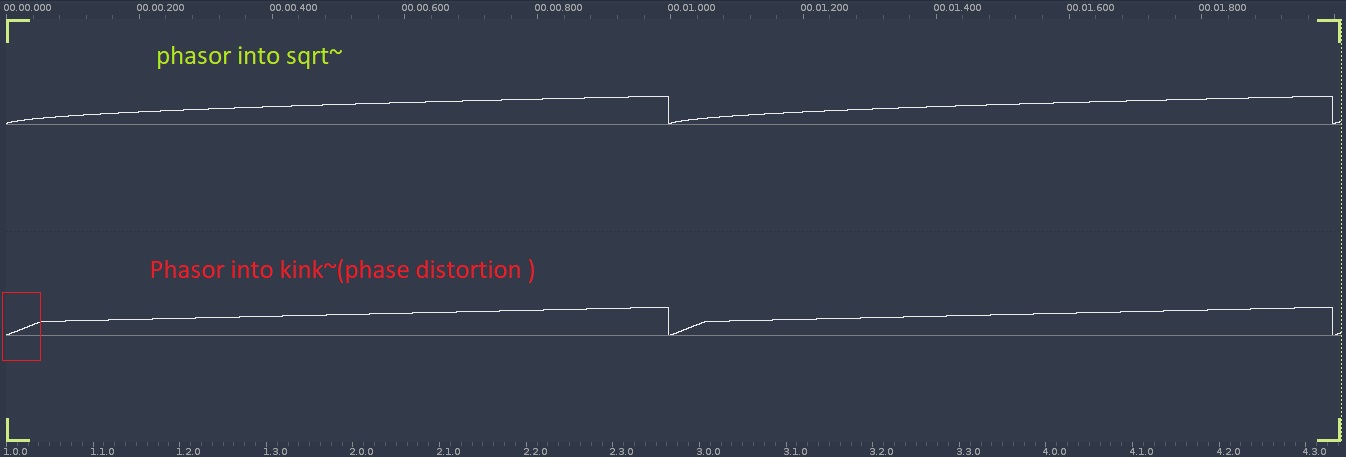
The line~ into sqrt does phase distortion
I compared it with ( cyclone ) kink~ (phasor into kink~) which adds a variabe breakpoint to the linear ramp of the phasor
First screenshot shows phasor into sqrt~(upper ) and lower phasor into kink~ .
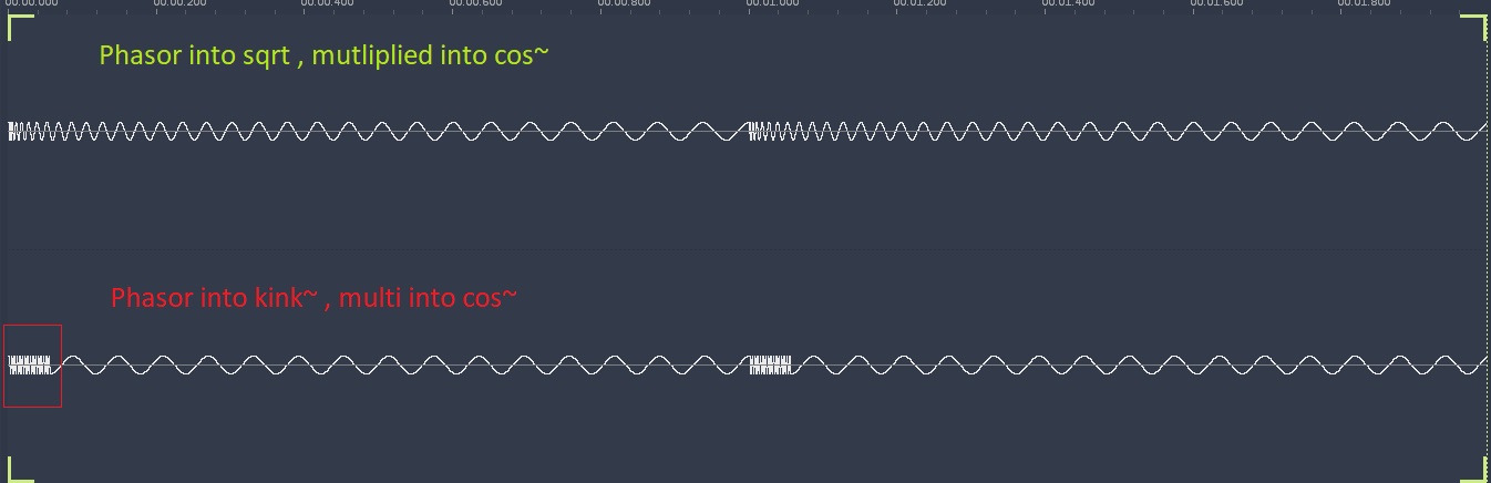
Second screenshot shows both outputs (left sqrt,right kink ) multiplied and into separate cosines .
The cosine when driven by kink ~ is obviously played a higher pitches before the breakpoint ( steeper rise ) and a steady lower pitch .after that . ( when using mul*)
The sqrt ~ becasue of the conitinous rise has a fallen pitchbend
Always worked with phase disrtion to distort ramps into lookuptables , kind of asurprise its capable of pitchbend
 posted in technical issues
looper overdubbing not lining up.....
Hey @whale-av and anyone else interested in this issue.
I'm still trying to wrap my head around this.
So this looper works if you loop one pass and play it. It works with overdubbing at speed = 1 or -1.. The problem is if you overdub at any speed other than 1 or -1.
I am going to explain the issue as I see it, although I may be mistaken. It is set up so the buffer length will not change after the first recording, so when overdubbing the buffer size doesn't change. If you doing playback at a speed other than 1 or -1 the speed of the phasor~ reading the array with the loop will change to that new speed. When you are done overdubbing, it would seem that the phasor~ should be at the same speed it was during the overdub, but if this is the case things get out of whack. At least that was my observation in the "simple3.pd" patch a few posts up.
I added an [expr] object to try and accomodate for what I was hearing. But now what is happening is it seems that the loop is getting shorter if it is less than 1 and it's too long if it's greater than 1.
I must be missing something obvious here.
I haven't tried this yet, but maybe I should add another phasor~ that is lined up to start with the first phasor~ playing the array, but when I alter playback speed this 2nd phasor will change as well and i can use that to start and stop the overdub process. What I am hearing is the overdub, when playing at speed = 2, will double in speed , then double in speed again during a recording. and the opposite is true for half speed. I think maybe a 2nd phasor can modulate to the new speed when an overdub is activated then take over reading the array when an overdub is finished. It's just an idea I had.
Anyway, any suggestions into this would be much appreciated.
Here is what I have now. simple6.pd
Thank you.
 posted in technical issues
get phase of [osc~]
[phasor~]
|
[cos~]
should be the same as
[osc~]
but this time I need to measure the phase of [osc~]
and do the same as
with [osc~] instead of [phasor~].
I have a running patch, but sometimes it flips the phase by 180 degrees.
Do you know why or how to avoid that?
Here is the patch:
phase_of_normalized_cosine~.pd
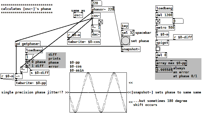
The patch calculates the phase of a normalized cosine y(x) by
asin(y(x)) / (pi/2)
this is a triangle wave, following cosine's shape linearized.
Then a tri-to-saw waveshper:
invert the falling part of the triangle
and divide it's frequency by 2.
late EDIT: also read this: https://forum.pdpatchrepo.info/topic/15128/snapshotting-and-restoring-the-state-of-a-phasor-exactly
 posted in technical issues
Signal logic - Clocks, Division and sequences
clock division and clock multiplication for a phaseaccumulator?
division is easy.
[*~ 4.]
[%~ 1.]
but multiplication is more or less impossible, as it would require something to count the current subcycle.
there are a workarounds though. if you want to use a phasor~ and a phasor~ which is 4 times slower, you could
a ) use multiple phasors~ from the beginning on and then select one of them
or, if you need them to be in sync with a "master phasor",
b ) use a phasor which is 8 times slower than the rated rate and derive the base speed phasor from it already using multiplication.
 posted in technical issues
Audio click occur when change start point and end point using |phasor~| and |tabread4~|
Hi Junzhe 
I often like to think through something like this with a concrete example.
Let's start with 10 seconds of audio: phasor = 0 --> time 0, phasor = 1 --> time 10000 (ms).
Then, at 5000 ms, you change the end time to 7000 ms.
So, now, phasor = 0.5, time = 5000. And you need phasor = 1 now to map onto 7000 ms.
So two things need to happen:
- The phasor, running at its current speed, would reach its end 5000 ms later -- but you actually need it to reach the end in 2000 ms. So the phasor's speed has to increase by a factor of 5/2 = current_time_to_end / new_time_to_end.
- The linear mapping currently locates phasor = 1 at time = 10000, but now you need phasor = 1 --> time 7000. So the slope of the linear mapping will have to adjust by a factor of 2/5 = new_time_to_end / current_time_to_end (and the linear function's intercept would have to change too).
The changes in phasor frequency and linear slope should cancel out.
Then, at the start of the next cycle (which can be detected by [samphold~]), you would have to recalculate the slope for the entire start <--> end segment.
I might be overthinking it, but e.g. jameslo admits that in a simpler solution "the pitch is not steady as you adjust the start and end" so I think there aren't many shortcuts to be taken.
BTW there is another way to integrate a rate: rpole~. With an integrator, you don't have to worry about rejiggering slopes -- it just continues on its way, and reaches the end value in its own time. But, you would be responsible for triggering the reset at that point. This version uses control messages for triggering, so it would be quantized to block boundaries. To do it sample-accurately involves feedback and I never worked that out.
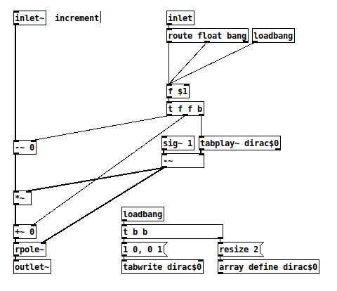
And a quick test patch (array "a" is 44100 samples, vertical range -10 to +50):
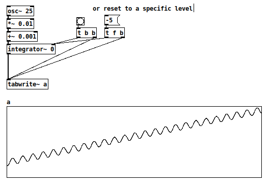
hjh
PS Hm, now I guess the [route float bang] isn't needed after all.
posted in technical issues