get phase of [osc~]
[phasor~]
|
[cos~]
should be the same as
[osc~]
but this time I need to measure the phase of [osc~]
and do the same as
with [osc~] instead of [phasor~].
I have a running patch, but sometimes it flips the phase by 180 degrees.
Do you know why or how to avoid that?
Here is the patch:
phase_of_normalized_cosine~.pd
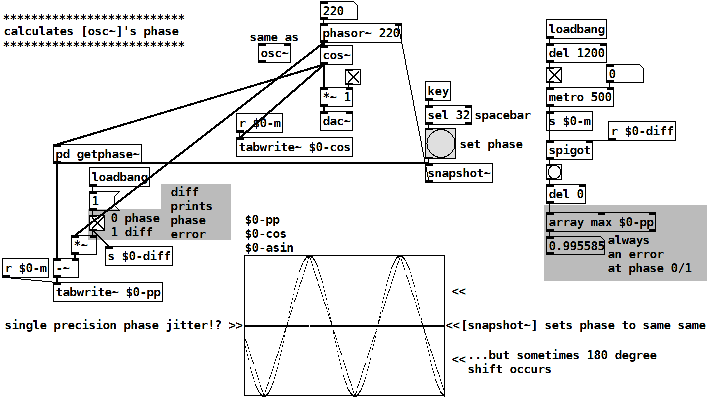
The patch calculates the phase of a normalized cosine y(x) by
asin(y(x)) / (pi/2)
this is a triangle wave, following cosine's shape linearized.
Then a tri-to-saw waveshper:
invert the falling part of the triangle
and divide it's frequency by 2.
late EDIT: also read this: https://forum.pdpatchrepo.info/topic/15128/snapshotting-and-restoring-the-state-of-a-phasor-exactly
 posted in technical issues
Signal logic - Clocks, Division and sequences
clock division and clock multiplication for a phaseaccumulator?
division is easy.
[*~ 4.]
[%~ 1.]
but multiplication is more or less impossible, as it would require something to count the current subcycle.
there are a workarounds though. if you want to use a phasor~ and a phasor~ which is 4 times slower, you could
a ) use multiple phasors~ from the beginning on and then select one of them
or, if you need them to be in sync with a "master phasor",
b ) use a phasor which is 8 times slower than the rated rate and derive the base speed phasor from it already using multiplication.
 posted in technical issues
Signal logic - Clocks, Division and sequences
@RT-Chris You would need something like Doc/G09_pitchshift.pd but accuracy would float out the window I think.
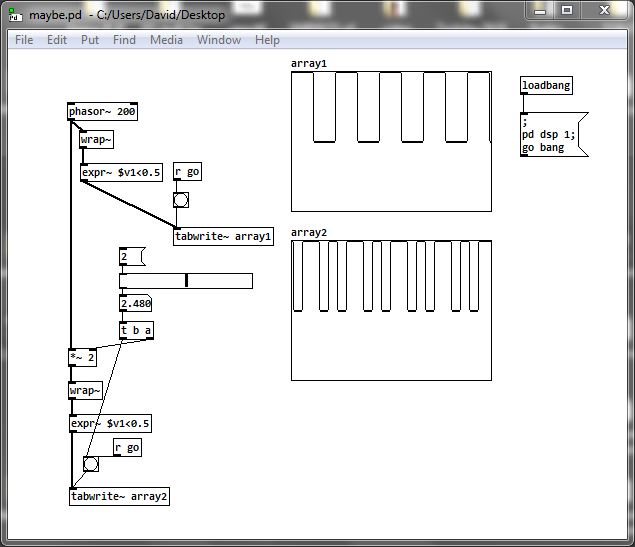
As you say [wrap~] can get you the square wave and some leeway on frequency......... https://forum.pdpatchrepo.info/topic/2628/phasor-vs-metro
Just built a test........ maybe.pd
You can get down to half the rate, but below that....... even changing the edge position will not help.
It looks as though there will be problems with increasing the rate above 2.... screenshot below....
...... except multiples of 2..... not sure... lost my maths hat...
The other problem is accuracy if you need a control signal sent from your patch, in which case [metro] is a better choice......... https://forum.pdpatchrepo.info/topic/4098/phasor-vs-metro .... as the block boundary will cause problems.
Of course I am probably wrong and there are solutions.....?
Maybe multiple [expr~] with different but relative edges?
But [wrap~] takes it out of phase so timing from the origin is all messed up anyway.
David.
 posted in technical issues
Audio click occur when change start point and end point using |phasor~| and |tabread4~|
Hi Junzhe 
I often like to think through something like this with a concrete example.
Let's start with 10 seconds of audio: phasor = 0 --> time 0, phasor = 1 --> time 10000 (ms).
Then, at 5000 ms, you change the end time to 7000 ms.
So, now, phasor = 0.5, time = 5000. And you need phasor = 1 now to map onto 7000 ms.
So two things need to happen:
- The phasor, running at its current speed, would reach its end 5000 ms later -- but you actually need it to reach the end in 2000 ms. So the phasor's speed has to increase by a factor of 5/2 = current_time_to_end / new_time_to_end.
- The linear mapping currently locates phasor = 1 at time = 10000, but now you need phasor = 1 --> time 7000. So the slope of the linear mapping will have to adjust by a factor of 2/5 = new_time_to_end / current_time_to_end (and the linear function's intercept would have to change too).
The changes in phasor frequency and linear slope should cancel out.
Then, at the start of the next cycle (which can be detected by [samphold~]), you would have to recalculate the slope for the entire start <--> end segment.
I might be overthinking it, but e.g. jameslo admits that in a simpler solution "the pitch is not steady as you adjust the start and end" so I think there aren't many shortcuts to be taken.
BTW there is another way to integrate a rate: rpole~. With an integrator, you don't have to worry about rejiggering slopes -- it just continues on its way, and reaches the end value in its own time. But, you would be responsible for triggering the reset at that point. This version uses control messages for triggering, so it would be quantized to block boundaries. To do it sample-accurately involves feedback and I never worked that out.
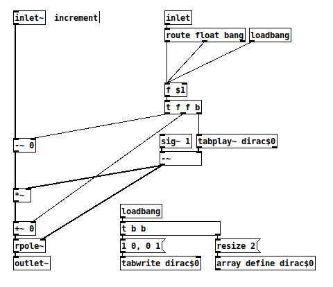
And a quick test patch (array "a" is 44100 samples, vertical range -10 to +50):
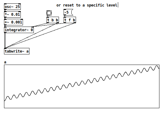
hjh
PS Hm, now I guess the [route float bang] isn't needed after all.
 posted in technical issues
s~/r~ throw~/catch~ latency and object creation order
For a topic on matrix mixers by @lacuna I created a patch with audio paths that included a s~/r~ hop as well as a throw~/catch~ hop, fully expecting each hop to contribute a 1 block delay. To my surprise, there was no delay. It reminded me of another topic where @seb-harmonik.ar had investigated how object creation order affects the tilde object sort order, which in turn determines whether there is a 1 block delay or not. Object creation order even appears to affect the minimum delay you can get with a delay line. So I decided to do a deep dive into a small example to try to understand it.
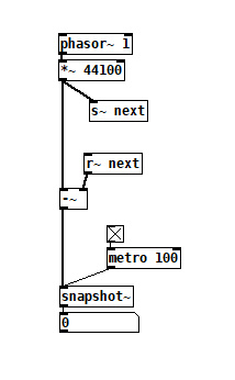
Here's my test patch: s~r~NoLatency.pd
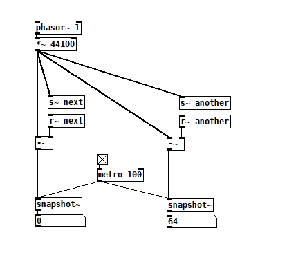
 The s~/r~ hop produces either a 64 sample delay, or none at all, depending on the order that the objects are created. Here's an example that combines both: s~r~DifferingLatencies.pd
 That's pretty kooky! On the one hand, it's probably good practice to avoid invisible properties like object creation order to get a particular delay, just as one should avoid using control connection creation order to get a particular execution order and use triggers instead. On the other hand, if you're not considering object creation order, you can't know what delay you will get without measuring it because there's no explicit sort order control. Well...technically there is one and it's described in G05.execution.order, but it defeats the purpose of having a non-local signal connection because it requires a local signal connection. Freeze dried water: just add water.
To reduce the number of cases I had to test, I grouped the objects into 4 subsets and permuted their creation orders:
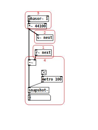 The order labeled in the diagram has no latency and is one that I just stumbled on, but I wanted to know what part of it is significant, so I tested all 24 permuations. (Methodology note: you can see the object creation order if you open the .pd file in a text editor. The lines that begin with "#X obj" list the objects in the order they were created.)
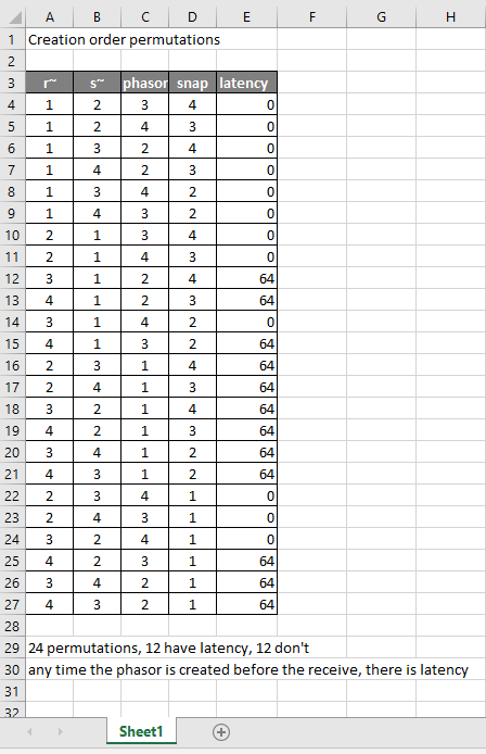
It appears that any time the phasor group is created before the r~, there is latency. Nothing else matters. Why would that be? To test if it's the whole audio chain feeding s~ that has to be created before, or only certain objects in that group, I took the first permutation with latency and cut/pasted [phasor~ 1] and [*~ 44100] in turn to push the object's creation order to the end. Only pushing [phasor~ 1] creation to the end made the delay go away, so maybe it's because that object is the head of the audio chain?
I also tested a few of these permutations using throw~/catch~ and got the same results. And I looked to see if connection creation order mattered but I couldn't find one that did and gave up after a while because there were too many cases to test.
So here's what I think is going on. Both [r~ next] and [phasor~ 1] are the heads of their respective locally connected audio chains which join at [-~]. Pd has to decide which chain to process first, and I assume that it has to choose the [phasor~ 1] chain in order for the data buffered by [s~ next] to be immediately available to [r~ next]. But why it should choose the [phasor~ 1] chain to go first if it's head is created later seems arbitrary to me. Can anyone confirm these observations and conjectures? Is this behavior documented anywhere? Can I count on this behavior moving forward? If so, what does good coding practice look like, when we want the delay and also when we don't?
 posted in technical issues
looking for velvet noise generator
@porres oh yeah I always forget about [expr~] for some reason.. maybe bc of the license it used to have.
There's no real reason to have the phase reset inlet, just more control.
From what I can tell, velvet noise is outputting a 1-sample impulse of value that's either 1 or -1, chosen randomly, at a random point in a regular period.
So I have a [phasor~] to keep track of the period, and the [samphold~] samples a random value from 0-1 when the [phasor~] resets. This will be the point in the phase of that period that the impulse will occur. When the [phasor~] gets to above or equal to this value, the [<~ ] will go from 1 to 0. That goes into [rzero~ 1], which will put out a -1 on the sample that occurs. That goes into the [==~ -1], which acts (together with [*~ ]) as a gate for the noise value that has been manipulated to either be 1 or -1, depending on if the output of [noise~] is positive or not.
The issue with this original implementation was that when the [phasor~] wraps around to start a new phase, it can wrap to a value greater than the new [samphold~] value from the noise. That means that if the noise value is very small, there will be no impulse for that period since the [phasor~] value will never be less than the sampled noise value for that period (and therefore the [<~ ] won't go from 1 to 0, which means the [rzero~ 1] below it won't output a -1, and so on). So, the [rzero~] and [<~ 0] put out a 1-sample value of 1 when the [phasor~] wraps around, which is combined with the other signal in [min~ 1] to take care of this. That way the [rzero~ 1] below the [min~ 1] will get a 1 even if the wrapped-around [phasor~] value is less than the new sampled noise value, and there will be an impulse for that period.
(that is what "make sure there is at least 1 1 on wraparound" means)
edit: after writing all of this it occurred to me that the sampled noise value could also be greater than the value that the [phasor~] will get to before it wraps around.. perhaps the solution is to constrain the sampled noise value depending on the frequency and phase of the [phasor~]...
 posted in technical issues
how can i make a [phasor~] myself?
my goal from doing this is to make a [phasor~], which only does one oscillation when it recieves a message, i can't simply use a line~ (at least AFAIK) to do this because i want to do FM on that [phasor~]. is there a way tho see what an object is made of, like opening a patch inside a patch, or is it just C code? i'm not good at C, BTW. could someone make a patch that does the same as [phasor~], or what i intend to do? both would be nice, because, if i just know haw the [phasor~] is made, i can probably transform it into what i need it for.
If none of the options above are possible, i have tried to use expr~/fexpr~ to time to turn off the [phasor~]/(output of [phasor~]), one attempt was with [fexpr~ if($x1[-1]==1,0,$x2[0])] where $x1 is the output of [phasor~], and $x2 is the frequency for [phasor~], and connect the output to [phasor~], but that didn't work. can somebody make a patch that reacts to [phasor~] reaching its peak: 1, and excactly between 1 and 0, when 1 is over and 0 has not started, and so turns the [phasor~] off?
help is greatly appreciated here:D
 posted in technical issues
samphold-ing a previous signal value
I would like to create a Pd equivalent of SuperCollider's LFDNoise1 LFO (random line segments).
It's basically like this. In Pd, I can see how to do almost all of it, except for sample/holding the previous random value.
(
a = {
    // pd: phasor~
    var phasor = LFSaw.ar(1) * 0.5 + 0.5,  // 0-1
    // pd: [rzero~ 1] --> [<~ 0]
    trig = HPZ1.ar(phasor) < 0,  // 1 when phasor drops
    // pd: [samphold~]
    nextEndpoint = Latch.ar(WhiteNoise.ar, trig),
    // pd: I don't know how to do this
    prevEndpoint = Latch.ar(Delay1.ar(nextEndpoint), trig),
    // pd: easy math
    line = (nextEndpoint - prevEndpoint) * phasor + prevEndpoint;

    // simple test signal: map bipolar LFO exponentially to freq
    SinOsc.ar(400 * (2 ** line), 0, 0.1).dup
}.play;
)

a.free;
I made one failed attempt using [phasor~] --> [rzero~ 1] --> [*~ -1] --> [threshold~] --> [random], but if the phasor jumps to zero in the middle of a control block, then the random calculation is out of sync and the output glitches slightly. So I need to keep all of it in the signal domain (no control objects).
Thanks,
hjh
posted in technical issues
Phase modulation FM8 emulation troubles
@RandLaneFly "When the mod index is maxed out it sounds way more extreme and than on the FM8."
Without looking at your patch --
I've always done FM (leaving PM aside for a moment) such that index = 1 means that, if f is the main frequency, the carrier frequency oscillates between 0 and 2f.
mod_phase = phasor(0 .. 2pi) at (f * ratio) Hz

mod = sin(mod_phase) * index

car_phase = phasor(0 .. 2pi) at (f + (f * mod)) Hz = (f * (1 + mod)) Hz

carrier = sin(car_phase)
If you do phase modulation like this, then index has exactly the same meaning.
mod_phase = phasor(0 .. 2pi) at (f * ratio) Hz

mod = sin(mod_phase) * index

car_phase = mod + phasor(0 .. 2pi) at f Hz

carrier = sin(car_phase)
Takeaway: if the phasor goes 0 to 2pi, then you don't need to do any extra scaling on the modulation index for PM and FM to be compatible.
The catch in Pure Data is that the phasor is not 0 to 2pi. It's 0 to 1.
So, for phase modulation, you have to scale the index down by 2pi: mod --> [/ 6.28319].
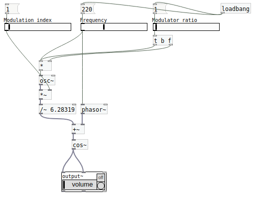
hjh
posted in technical issues
PD's scheduler, timing, control-rate, audio-rate, block-size, (sub)sample accuracy,
Hello, 
this is going to be a long one.
After years of using PD, I am still confused about its' timing and schedueling.
I have collected many snippets from here and there about this topic,
-wich all together are really confusing to me.
*I think it is very important to understand how timing works in detail for low-level programming … *
(For example the number of heavy jittering sequencers in hard and software make me wonder what sequencers are made actually for ? lol )
This is a collection of my findings regarding this topic, a bit messy and with confused questions.
I hope we can shed some light on this.


- a)
The first time, I had issues with the PD-scheduler vs. how I thought my patch should work is described here:
https://forum.pdpatchrepo.info/topic/11615/bang-bug-when-block-1-1-1-bang-on-every-sample
The answers where:
„
[...] it's just that messages actually only process every 64 samples at the least. You can get a bang every sample with [metro 1 1 samp] but it should be noted that most pd message objects only interact with each other at 64-sample boundaries, there are some that use the elapsed logical time to get times in between though (like vsnapshot~)
also this seems like a very inefficient way to do per-sample processing..
https://github.com/sebshader/shadylib http://www.openprocessing.org/user/29118
seb-harmonik.ar posted about a year ago , last edited by seb-harmonik.ar about a year ago
• 1
 whale-av
@lacuna An excellent simple explanation from @seb-harmonik.ar.
Chapter 2.5 onwards for more info....... http://puredata.info/docs/manuals/pd/x2.htm
David.
“
There is written: http://puredata.info/docs/manuals/pd/x2.htm
„2.5. scheduling
Pd uses 64-bit floating point numbers to represent time, providing sample accuracy and essentially never overflowing. Time appears to the user in milliseconds.
2.5.1. audio and messages
Audio and message processing are interleaved in Pd. Audio processing is scheduled every 64 samples at Pd's sample rate; at 44100 Hz. this gives a period of 1.45 milliseconds. You may turn DSP computation on and off by sending the "pd" object the messages "dsp 1" and "dsp 0."
In the intervals between, delays might time out or external conditions might arise (incoming MIDI, mouse clicks, or whatnot). These may cause a cascade of depth-first message passing; each such message cascade is completely run out before the next message or DSP tick is computed. Messages are never passed to objects during a DSP tick; the ticks are atomic and parameter changes sent to different objects in any given message cascade take effect simultaneously.
In the middle of a message cascade you may schedule another one at a delay of zero. This delayed cascade happens after the present cascade has finished, but at the same logical time.
2.5.2. computation load
The Pd scheduler maintains a (user-specified) lead on its computations; that is, it tries to keep ahead of real time by a small amount in order to be able to absorb unpredictable, momentary increases in computation time. This is specified using the "audiobuffer" or "frags" command line flags (see getting Pd to run ).
If Pd gets late with respect to real time, gaps (either occasional or frequent) will appear in both the input and output audio streams. On the other hand, disk strewaming objects will work correctly, so that you may use Pd as a batch program with soundfile input and/or output. The "-nogui" and "-send" startup flags are provided to aid in doing this.
Pd's "realtime" computations compete for CPU time with its own GUI, which runs as a separate process. A flow control mechanism will be provided someday to prevent this from causing trouble, but it is in any case wise to avoid having too much drawing going on while Pd is trying to make sound. If a subwindow is closed, Pd suspends sending the GUI update messages for it; but not so for miniaturized windows as of version 0.32. You should really close them when you aren't using them.
2.5.3. determinism
All message cascades that are scheduled (via "delay" and its relatives) to happen before a given audio tick will happen as scheduled regardless of whether Pd as a whole is running on time; in other words, calculation is never reordered for any real-time considerations. This is done in order to make Pd's operation deterministic.
If a message cascade is started by an external event, a time tag is given it. These time tags are guaranteed to be consistent with the times at which timeouts are scheduled and DSP ticks are computed; i.e., time never decreases. (However, either Pd or a hardware driver may lie about the physical time an input arrives; this depends on the operating system.) "Timer" objects which meaure time intervals measure them in terms of the logical time stamps of the message cascades, so that timing a "delay" object always gives exactly the theoretical value. (There is, however, a "realtime" object that measures real time, with nondeterministic results.)
If two message cascades are scheduled for the same logical time, they are carried out in the order they were scheduled.
“
[block~ smaller then 64] doesn't change the interval of message-control-domain-calculation?,
Only the size of the audio-samples calculated at once is decreased?
Is this the reason [block~] should always be … 128 64 32 16 8 4 2 1, nothing inbetween, because else it would mess with the calculation every 64 samples?
How do I know which messages are handeled inbetween smaller blocksizes the 64 and which are not?
How does [vline~] execute?
Does it calculate between sample 64 and 65 a ramp of samples with a delay beforehand, calculated in samples, too - running like a "stupid array" in audio-rate?
While sample 1-64 are running, PD does audio only?
[metro 1 1 samp]
How could I have known that? The helpfile doesn't mention this. EDIT: yes, it does.
(Offtopic: actually the whole forum is full of pd-vocabular-questions)
How is this calculation being done?
But you can „use“ the metro counts every 64 samples only, don't you?
Is the timing of [metro] exact? Will the milliseconds dialed in be on point or jittering with the 64 samples interval?
Even if it is exact the upcoming calculation will happen in that 64 sample frame!?
- b )


There are [phasor~], [vphasor~] and [vphasor2~] … and [vsamphold~]
https://forum.pdpatchrepo.info/topic/10192/vphasor-and-vphasor2-subsample-accurate-phasors
“Ive been getting back into Pd lately and have been messing around with some granular stuff. A few years ago I posted a [vphasor.mmb~] abstraction that made the phase reset of [phasor~] sample-accurate using vanilla objects. Unfortunately, I'm finding that with pitch-synchronous granular synthesis, sample accuracy isn't accurate enough. There's still a little jitter that causes a little bit of noise. So I went ahead and made an external to fix this issue, and I know a lot of people have wanted this so I thought I'd share.
[vphasor~] acts just like [phasor~], except the phase resets with subsample accuracy at the moment the message is sent. I think it's about as accurate as Pd will allow, though I don't pretend to be an expert C programmer or know Pd's api that well. But it seems to be about as accurate as [vline~]. (Actually, I've found that [vline~] starts its ramp a sample early, which is some unexpected behavior.)
[…]
“
- c)


Later I discovered that PD has jittery Midi because it doesn't handle Midi at a higher priority then everything else (GUI, OSC, message-domain ect.)
EDIT:
Tryed roundtrip-midi-messages with -nogui flag:
still some jitter.
Didn't try -nosleep flag yet (see below)
- d)

So I looked into the sources of PD:
scheduler with m_mainloop()
https://github.com/pure-data/pure-data/blob/master/src/m_sched.c
And found this paper
Scheduler explained (in German):
https://iaem.at/kurse/ss19/iaa/pdscheduler.pdf/view
wich explains the interleaving of control and audio domain as in the text of @seb-harmonik.ar with some drawings
plus the distinction between the two (control vs audio / realtime vs logical time / xruns vs burst batch processing).
And the "timestamping objects" listed below.
And the mainloop:
Loop
- messages (var.duration)
- dsp (rel.const.duration)
- sleep
With
[block~ 1 1 1]
calculations in the control-domain are done between every sample? But there is still a 64 sample interval somehow?
Why is [block~ 1 1 1] more expensive? The amount of data is the same!? Is this the overhead which makes the difference? Calling up operations ect.?
Timing-relevant objects
from iemlib:
[...]
iem_blocksize~   blocksize of a window in samples
iem_samplerate~  samplerate of a window in Hertz


------------------ t3~ - time-tagged-trigger --------------------
-- inputmessages allow a sample-accurate access to signalshape --
t3_sig~          time tagged trigger sig~
t3_line~         time tagged trigger line~


--------------- t3 - time-tagged-trigger  ---------------------
----------- a time-tag is prepended to each message -----------
----- so these objects allow a sample-accurate access to ------
---------- the signal-objects t3_sig~ and t3_line~ ------------
t3_bpe           time tagged trigger break point envelope
t3_delay         time tagged trigger delay
t3_metro         time tagged trigger metronom
t3_timer         time tagged trigger timer

[...]
What are different use-cases of [line~] [vline~] and [t3_line~]?
And of [phasor~] [vphasor~] and [vphasor2~]?
When should I use [block~ 1 1 1] and when shouldn't I?
[line~] starts at block boundaries defined with [block~] and ends in exact timing?
[vline~] starts the line within the block?
and [t3_line~]???? Are they some kind of interrupt? Shortcutting within sheduling???
- c) again)

https://forum.pdpatchrepo.info/topic/1114/smooth-midi-clock-jitter/2
I read this in the html help for Pd:
„
MIDI and sleepgrain
In Linux, if you ask for "pd -midioutdev 1" for instance, you get /dev/midi0 or /dev/midi00 (or even /dev/midi). "-midioutdev 45" would be /dev/midi44. In NT, device number 0 is the "MIDI mapper", which is the default MIDI device you selected from the control panel; counting from one, the device numbers are card numbers as listed by "pd -listdev."
The "sleepgrain" controls how long (in milliseconds) Pd sleeps between periods of computation. This is normally the audio buffer divided by 4, but no less than 0.1 and no more than 5. On most OSes, ingoing and outgoing MIDI is quantized to this value, so if you care about MIDI timing, reduce this to 1 or less.
„
Why is there the „sleep-time“ of PD? For energy-saving??????
This seems to slow down the whole process-chain?
Can I control this with a startup flag or from withing PD? Or only in the sources?
There is a startup-flag for loading a different scheduler, wich is not documented how to use.
- e)

[pd~] helpfile says:
ATTENTION: DSP must be running in this process for the sub-process to run. This is because its clock is slaved to audio I/O it gets from us!
Doesn't [pd~] work within a Camomile plugin!?
How are things scheduled in Camomile? How is the communication with the DAW handled?
- f)

and slightly off-topic:
There is a batch mode:
https://forum.pdpatchrepo.info/topic/11776/sigmund-fiddle-or-helmholtz-faster-than-realtime/9
EDIT:
- g)
I didn't look into it, but there is:
https://grrrr.org/research/software/
clk – Syncable clocking objects for Pure Data and Max
This library implements a number of objects for highly precise and persistently stable timing, e.g. for the control of long-lasting sound installations or other complex time-related processes.
Sorry for the mess!
Could you please help me to sort things a bit? Mabye some real-world examples would help, too.

posted in technical issues