Little help with pitshifter.
oh shoot! okay. I use a vline~ to feed tabread4~ so the method is a little different
The mtof part is designed to calculate a ratio - so if you input a zero into the left part, the result is one. If you input something like -5, it will give you a value that is less than one. You can multiply that value by the length of the sample in ms to get how long the sample would play back if you wanted it to play at 5 semitones above(?) the base pitch of the sample. You have to choose a midi note to start at. Above that note, the sample will play faster, below that note the sample will play slower. I think I calculate this value by taking the base note and subtracting from that the note from the midi keyboard.
You want to use the tabread4~ method from the (3.7.1.1.) example, but instead of feeding it with a phasor~, try feeding it with a vline~. Then you can calculate the length in samples of your sample. That's the left output of soundfiler. Dividing length in samples by the samplerate~ gives you the lenght of the sample in seconds. Multiply that by 1000 and you have the the length in milliseconds. vline~ takes input in milliseconds. Send it a message to ramp from 0 to the number of samples in your sample in the number of milliseconds you just calculated. If you want to repitch it, also multiply by the midi ratio from above.
If you want to use phasor~ instead, you're setting frequency in Hz. So instead of multiplying the sample length by 1000, you might want to multiply it by the ratio and then get the reciprocal of it with this:

Then feed that to the phasor~
Are you going to use phasor~ in your design? I could double check that there's not a better transposing method with phasor.
Actually, it might be way easier with phasor, You could convert your current input to phasor to midi with ftom, then add transposition in semitones and then convert back to a frequency...
 posted in abstract~
Tabwrite~/array has problems working as a long timebase oscilloscope?
Hi all,
I needed to have some more long-running visualisation of waveforms in PD, so as there is no vanilla [scope~] object, I thought I'd use [tabwrite~] with [array], as commonly recommended - however, I have stumbled upon a somewhat strange behavior, which I'm not sure whether it's a bug. This is on Ubuntu 18.04, vanilla Puredata from Ubuntu repos (0.48.1-3)
So, basically I made a patch, which is mostly reused help of [tabwrite~] :
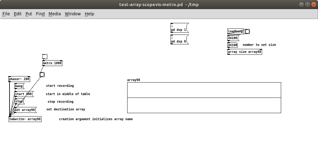
The patch itself is here: test-array-scopevis-metro.pd
So, basically, I want to view signals as if on a scope with timebase of 1 second. My PD/Media/Audio Settings tells me: Sample rate: 44100, Block size: 64, Delay (msec): 25
So, all I have in addition to what was there in the [tabwrite~] help, is a few objects to set the array98 array size to 44100 when the patch is loaded - so there is enough memory to record 1 second of signal. And then I've added a metro, so it bangs the tabwrite~ each second (each 1000 msec) - the idea being that I bang the tabwrite~, it records 44100 samples in a second and shows them, then after that second I bang again, it records 44100 samples in a second and shows them anew and so on - pretty much like an oscilloscope at a timebase of 1 sec would do.
However, the actual response is shown in this video:
That is, when I start the metro at 1000 msec, it keeps banging for at least 10 times, without the array ever refreshing the waveform display?! Then, when I stop the metro, the waveform is displayed ?! At that point, I draw whatever in the array graph so as to "reset" this display, change the metro to 1001 msec - and start the metro again. This time the display does update as expected - but only after an initial delay of some 2 seconds (or three bangs) - I would have otherwise expected a delay of 1 second (two bangs).
Does anyone knows why this happens, and how to get a more reliable behavior for this kind of case? My guess is, for a [metro 1000], PD actually does not have enough time to fill the entire array with all 44100 samples, and thus it never updates the graph - apparently 1 millisecond extra is enough for PD to realize that the array has been filled, and so it updates the graph, but then why does it take 2 sec (at 3rd bang) to update, and not only 1 second (at 2nd bang)?
 posted in technical issues
prophet 3003 wavetable synth prototype
hi folks, thanks for the kind comments!
sure ill share the patch eventually but right now its an uncommented messy laboratory affair. best thing you can do right now is look at the patch image above which is quite self explanatory.
here is the vs rom in one wav file, scan this in 128 chunks of 128 samples and you have the single wave data.
harmonic aliasing is best described by acreil in the above mentioned blog post because thats where i got the idea from. the rest is trial and error and a lot of listening to integer combinations.
harmonic aliasing is actually my own term for what im trying to do. here is how i would describe it:
-
if you repeat 128 samples with a phasor at 128 hz (or 64/32/16/8/4/2) or any multiple of 128 your phasor restarts exactly at the beginning of the wave data and the aliasing frequencies generated by the steppyness of the data will follow the harmonic overtone series 1,2,3 etc. depending on the multiple.
-
if you introduce another prime divider ie. 3 as in 128 / 3 the phasor will line up with the sample data every 3rd sample and the osc will alias at the 3rd subharmonic frequency which will be somewhat more disharmonic than any overtone.
-
another way to look at it would be the pattern repetitions. at subdivision 5 the phasor starts at 5 different points in the sample data and its easy to imagine that the readout patterns are all slightly different ... but the whole thing cycles after 5 phasor rounds = 5th subharmonic..
-
if you subdivide 128 further with a higher prime ie. 563 you will get 562 different sounding samples until nr. 563 lines up again. get the idea?
this is all very easy to hear once you experiment with prime subdivisions and multiplications. just remember its all based on synching the data flow from the sample with the frequency of the index phasor. this will work with ANY sample data, the vs rom is just cool to use for vintage synth fans.
whats important for proper aliasing is that you use a simple [tabread] into the data without any interpolation like tabread4 or oversampling!
all the other elements in the synth like delay, waveshaper, sequencer follow the same rule as they are just repetition devices like the wavetable oscillator.
if you finally synch everything to the sample rate of your soundcard the voltages that hit your speakers will repeat in exact patterns. thats the idea of this synth: precision number repetition controlled by harmonic/disharmonic integer combinations ... just like the great 80s synths waldorf microwave or prophet vs.
 posted in output~
{lop~} controlled by {adc~} via potentiometer
3 things:
-
The signal outlet from the [*~ ] object should go into the [snapshot~] , not the [metro]. [metro] is a control level object and can't take signal input. [snapshot~] takes a signal for its source and a control level "bang" message to trigger it, both in the same input.
-
There's no need to use [bang~] and metro at the same time. [bang~] is essentially a metro already, firing once every DSP cycle, which is faster than [metro] can manage. So either use [bang~] to send a "bang" message at the highest possible rate, or use [metro] to send a "bang" message at any other rate.
-
A low-pass filter plus a high-pass filter is equivalent to a band-pass filter. There are several band-pass filters in PD to choose from, including [bp~] and [vcf~]. [vcf~] has a signal input for the centre frequency, so if you use this, you won't need to worry about converting signal to control at all.
 posted in technical issues
Metro sync
@CBronisimo The easiest way to do such a thing is to use a metro as a clock signal at the fastest time division you'd like to obtain. Then use a counter, a [mod N] and a [sel 0] to bang every N beats.
This way you can have lots of pseudo-metro functions that depend on just one metro, and they will be in sync every time. Obviously you'll have to reset the counter if you stop and restart the clock metro.
For example, if you want a whole time to beat every 1000 ms, set metro to 1000/32, then use [mod 32] to bang whole time, [mod 16] to bang 1/2, [mod 8] to bang 1/4 and so on up to 1/32 with no mod at all, or [mod 64] to bang twice the time etc... If you plan to go even faster just set the clock metro to 1000/64 or 1000/128 and change [mod N] accordingly. You can even get dotted and odd time signatures this way.
Hope this helps!
 posted in technical issues
siwtch/case in pd ? (IN VANILLA)
@phil123456 It's hard to tell with the picture.... but it looks as though sending the number to all of the [pd phaser-bank] objects and letting them decide how to "use" that number would be easiest.
If you make an abstraction of [pd phaser-bank] as maybe [phaser-bank] and then place that many times in the patch with a number argument........
[phaser-bank 1]
[phaser-bank 2]
[phaser-bank 3]
etc.
Then in [phaser-bank] you could use
[r number_being_sent]
|
[t b f]
| |
[$1<]
|
[do it $1 times]
to let the abstraction decide it's action...........
Does that make sense? it was posted in a hurry....
David.
 posted in patch~
Arduino Stepper Motor
Hi, this is the driver that i connect to arduino : http://ruggedcircuits.com/html/rugged_motor_driver.html
in arduino I've a patch that read the PWM of two pin and i need to write a sequence like this with the digitals output :
void StepperHighSpeed::stepMotor(int thisStep)
{
if (this->pin_count == 2) {
switch (thisStep) {
case 0: /* 01 */
digitalWrite(motor_pin_1, LOW);
digitalWrite(motor_pin_2, HIGH);
break;
case 1: /* 11 */
digitalWrite(motor_pin_1, HIGH);
digitalWrite(motor_pin_2, HIGH);
break;
case 2: /* 10 */
digitalWrite(motor_pin_1, HIGH);
digitalWrite(motor_pin_2, LOW);
break;
case 3: /* 00 */
digitalWrite(motor_pin_1, LOW);
digitalWrite(motor_pin_2, LOW);
break;
}
did someone can help me ?
Thanks
Best
Enrico
 posted in I/O hardware diy
JKP - Bangboum
Sorry I'm getting errors, can you help me?
I've installed the montreal mtl library, but still I have too many objects missing
mtl/qompander~ /id compander
... couldn't create
mtl/clkMaster 120
... couldn't create
setting pattern to default: /home/leopard/Documenti/Music/_sperimentazioni/_PURE DATA/Bangboum/./moteur/*
[msgfile] part of zexy-2.2.3 (compiled: Sep 22 2010)
Copyright (l) 1999-2008 IOhannes m zmölnig, forum::für::umläute & IEM
mtl/player~
... couldn't create
mtl/clkSlave 4 16
... couldn't create
mtl/kick808~
... couldn't create
mtl/clkSlave 1 4
... couldn't create
setting pattern to default: /home/leopard/Documenti/Music/_sperimentazioni/_PURE DATA/Bangboum/./moteur/*
mtl/player~
... couldn't create
setting pattern to default: /home/leopard/Documenti/Music/_sperimentazioni/_PURE DATA/Bangboum/./moteur/*
mtl/player~
... couldn't create
setting pattern to default: /home/leopard/Documenti/Music/_sperimentazioni/_PURE DATA/Bangboum/./moteur/*
mtl/player~
... couldn't create
setting pattern to default: /home/leopard/Documenti/Music/_sperimentazioni/_PURE DATA/Bangboum/./moteur/*
mtl/player~
... couldn't create
setting pattern to default: /home/leopard/Documenti/Music/_sperimentazioni/_PURE DATA/Bangboum/./moteur/*
mtl/player~
... couldn't create
setting pattern to default: /home/leopard/Documenti/Music/_sperimentazioni/_PURE DATA/Bangboum/./moteur/*
mtl/player~
... couldn't create
setting pattern to default: /home/leopard/Documenti/Music/_sperimentazioni/_PURE DATA/Bangboum/./moteur/*
mtl/player~
... couldn't create
 posted in patch~
Phasor~ as index to tabread~ with del and line~ envelope glitch
Hey
I'm using phasor for an index to a tabread~ to play a sample.
I'm also using line~ as an envelope to control audio output.
The timing for the envelope is set by the size of the sample size and samplerate~ as well as the frequency for the phasor~.
The magnitude of the phasor is adjusted to the sample size.
The sample player can be re-triggered and when this happens a line~ is set to go to 0 in 5ms,
a delay is set for 5ms,
then bangs another line~ to go to velocity in 0,
as well as setting phasor~ frequency to 1/t and phase to zero.
At which time another delay is setup at samplelength in ms.
After the sample is played the phasor~ frequency is set to 0 then
another line~ to 0 in 5ms is sent to the [*~] .
This causes a glitch when the sample is retriggered because the phasor~ is reset to zero and starts replaying the sample.
This glitch can not be heard when the sample is not re-triggered so maybe it's a control vs signal timing issue.
I did hear the glitch at the end of the sample re-triggered or not using vline~.
So my question is how do you do audio rate envelope triggering of envelopes ? I would post the patch but it is a mess. A good answer or pointer to some reference material would be greatly appreciated. I haven't quite wrapped my head around the sample and hold sampler examples yet.
 posted in technical issues
Phasor~ vs metro
The choice really depends on how you want to work. With [phasor~] it's (generally) pretty easy to use one master [phasor~] and divide the signal into whatever subdivisions you may need. You can also do smoother tempo changes since the frequency can be updated at audio rate. But while you have a sample-accurate clock, converting it into messages/bangs loses that accuracy. [edge~] and [threshold~] are the only objects that I've used to convert a [phasor~] clock to bangs, and both conform to block boundaries and have a minimum limit of 64 samples. So if you need sample accuracy with [phasor~], then you have to find a way to keep your events triggered with audio signals, which is not very easy.
[metro] is really just easier, and for a drum machine it's probably the best way to go. Pd's [metro] is pretty damn accurate (it's the one in Max that is prone to drift). Most of the time you'll be triggering events at message rate, and so using [metro] with objects like [vline~] will actually be more accurate than [phasor~]. And for a drum machine, you might find that pretty important.
 posted in technical issues