Pd compiled for double-precision floats and Windows
@jameslo said:
@ddw_music So in the case of c#, Pd64 and SC, are the non-zero numbers past the precision limit real?
lacuna beat me to the punch, but I already wrote some stuff up from a slightly different perspective. Maybe this will fill in some gaps.
In short: Yes, those "extra digits" accurately reflect the number that's being stored.
Sticking with single precision... you get 1 sign bit, 8 exponent bits, and 23 mantissa bits (for 24 bits of precision in the mantissa, because in scientific notation, there's one nonzero digit to the left of the point, and in binary, there's only one nonzero digit, so it doesn't have to be encoded).
Binary long division: 1 over 1010 (1010 = decimal 8+2 = decimal 10).
       0.00011001100....
      __________
1010 ) 1.0000 - 16/10
         1010
         ----
          1100 - remainder 6, then add a digit = 12/10
          1010
          ----
          00100 - remainder 2, then add a digit = 4/10
            1000 - 8/10
            10000 - 16/10 repeating from here
= 1.10011001100110011001100 * 2^(-4)
The float encoding has a finite number of digits -- therefore it must be a rational number. Moving the binary point 23 places to the right, and compensating in the exponent:
110011001100110011001100 * 2^(-27)
= 0xCCCCCC / 2^27
= 13421772 / 134217728
Just to be really pedantic, I went ahead and coded step-by-step decimal long division in SC, and I get:
~longDiv.(13421772, 134217728, maxIter: 50);
-> 0.0999999940395355224609375
... which is below the IEEE result. That's because I just naively truncated the mantissa -- I think IEEE's algorithm (when populating the float in the first place, or when dividing) recognizes that the next bit would be 1, and so, rounds up:
~longDiv.(13421773, 134217728, maxIter: 50);
-> 0.100000001490116119384765625
... matching lacuna's post exactly.
Division by large powers of two, in decimal, produces a lot of decimal digits below the point -- but it will always terminate.
hjh
 posted in technical issues
Pd compiled for double-precision floats and Windows
@jameslo said:
@ddw_music I love that story but am scratching my head over the 1/10 example you gave. Here's a test I made in Arduino c++: ... I went out 40 digits and didn't see anything unexpected. Was that example you gave just a metaphor for the issue, or is my test naive?
Not a metaphor at all:
[16, 17, 40].do { |prec|
"% digits: %\n".postf(
prec,
0.1.asStringPrec(prec)
)
};
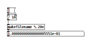
16 digits: 0.1
17 digits: 0.10000000000000001
40 digits: 0.1000000000000000055511151231257827021182
As for Arduino, the float datatype reference says "Unlike other platforms, where you can get more precision by using a double (e.g. up to 15 digits), on the Arduino, double is the same size as float" -- so my guess here is that Serial places a limit on the number of digits it will try to render, and then fills the rest with zeros.
I went out 40 digits and didn't see anything unexpected.
Seeing zeros all the way out to 40 digits is unexpected! Arduino's output here is more comforting to end-users (which might be why they did that), but it isn't accurate.
Considering that Arduino calculates "double" using single precision, the output should deviate from the mathematically true value even earlier:
// 0.1.as32Bits = single precision but as an integer
// Float.from32Bits = double precision but based on the 32 bit float
Float.from32Bits(0.1.as32Bits).asStringPrec(40)

-> 0.100000001490116119384765625
The most reasonable conclusion I can draw is that Arduino is gussying up the output to reduce the number of "what the xxx is it printing" questions on their forum. That should not be taken as a standard against which other software libraries may be judged.
Edit: hmm, but here's Pd64.
Pd64 is doing it right, and Arduino is not.
Getting back to how Pd seems to differ from other programming languages, I'm going to hazard a guess and say that Pd hasn't separated the value of a float from its display/storage format.
The value must be stored in standard single/double precision format. You need the CPU to be able to take advantage of floating point instructions.
It's rather that Pd has to render the arguments as text, and this part isn't syncing up with the "double" compiler switch.
PS I hope my attempt at humor didn't discourage @porres from responding to @oid's question. I'm sure he would have something more meaningful to contribute.
Of patchers as programming languages... well, I got a lot of opinions about that. Another time. For now, just to say, classical algorithms are much harder to express in patchers because patchers are missing a few key features of programming languages.
hjh
posted in technical issues
Ultrasonic distance sensors with Pd in Bela
The ultrasonic distance sensors are usually digital, not analog. If this is the case, you're trying to read a digital signal as analog, which doesn't make much sense. This sensor has two pins, a trigger and an echo. You have to send a high voltage to the trigger pin, then pull it low, and read the echo pin which will help you compute the distance based on the time it took for this trigger pulse to arrive back at the echo pin.
The code below (copied from Arduino'g Project Hub), uses Arduino's pulseIn() function, to compute the distance:
// Define Trig and Echo pin:
#define trigPin 2
#define echoPin 3
//  Define variables:
long duration;
int distance;
void setup() {
  // Define  inputs and outputs:
  pinMode(trigPin, OUTPUT);
  pinMode(echoPin, INPUT);
  //Begin Serial communication at a baudrate of 9600:
  Serial.begin(9600);
}
void  loop() {
  digitalWrite(trigPin, LOW);
  delayMicroseconds(5);
  digitalWrite(trigPin,  HIGH);
  delayMicroseconds(10);
  digitalWrite(trigPin, LOW);
  // Read  the echoPin, pulseIn() returns the duration (length of the pulse) in microseconds:
  duration = pulseIn(echoPin, HIGH);
  // Calculate the distance:
  distance=  duration*0.034/2;
  // Print the distance on the Serial Monitor
  Serial.print("Distance  = ");
  Serial.print(distance);
  Serial.println(" cm");
  delay(1000);
}
I searched online and found the source of this pulseIn() function in Arduino's forum, which is this:
/*
  wiring_pulse.c - pulseIn() function
  Part of Arduino - http://www.arduino.cc/

  Copyright (c) 2005-2006 David A. Mellis

  This library is free software; you can redistribute it and/or
  modify it under the terms of the GNU Lesser General Public
  License as published by the Free Software Foundation; either
  version 2.1 of the License, or (at your option) any later version.

  This library is distributed in the hope that it will be useful,
  but WITHOUT ANY WARRANTY; without even the implied warranty of
  MERCHANTABILITY or FITNESS FOR A PARTICULAR PURPOSE.  See the GNU
  Lesser General Public License for more details.

  You should have received a copy of the GNU Lesser General
  Public License along with this library; if not, write to the
  Free Software Foundation, Inc., 59 Temple Place, Suite 330,
  Boston, MA  02111-1307  USA

  $Id: wiring.c 248 2007-02-03 15:36:30Z mellis $
*/

#include "wiring_private.h"
#include "pins_arduino.h"

/* Measures the length (in microseconds) of a pulse on the pin; state is HIGH
 * or LOW, the type of pulse to measure.  Works on pulses from 2-3 microseconds
 * to 3 minutes in length, but must be called at least a few dozen microseconds
 * before the start of the pulse. */
unsigned long pulseIn(uint8_t pin, uint8_t state, unsigned long timeout)
{
    // cache the port and bit of the pin in order to speed up the
    // pulse width measuring loop and achieve finer resolution.  calling
    // digitalRead() instead yields much coarser resolution.
    uint8_t bit = digitalPinToBitMask(pin);
    uint8_t port = digitalPinToPort(pin);
    uint8_t stateMask = (state ? bit : 0);
    unsigned long width = 0; // keep initialization out of time critical area

    // convert the timeout from microseconds to a number of times through
    // the initial loop; it takes 16 clock cycles per iteration.
    unsigned long numloops = 0;
    unsigned long maxloops = microsecondsToClockCycles(timeout) / 16;

    // wait for any previous pulse to end
    while ((*portInputRegister(port) & bit) == stateMask)
        if (numloops++ == maxloops)
            return 0;

    // wait for the pulse to start
    while ((*portInputRegister(port) & bit) != stateMask)
        if (numloops++ == maxloops)
            return 0;

    // wait for the pulse to stop
    while ((*portInputRegister(port) & bit) == stateMask) {
        if (numloops++ == maxloops)
            return 0;
        width++;
    }

    // convert the reading to microseconds. The loop has been determined
    // to be 20 clock cycles long and have about 16 clocks between the edge
    // and the start of the loop. There will be some error introduced by
    // the interrupt handlers.
    return clockCyclesToMicroseconds(width * 21 + 16);
}
This is already getting complicated, as pulseIn() uses other functions which should be found and translated to Pd. I guess the best thing you can do is try to translate the first code chuck in this reply to Pd, and when you read a high voltage in the echo pin, do some math to calculate the distance.
In essence, set a digital input and a digital output pin on the Bela, trigger the output pin with a high and low signal, and keep reading the input pin (you should probably use a pull-down resistor there), until you get a high. Calculate the time it took with the [timer] object and do some simple math to get the distance. Do that with distances you know first, and then use the rule of three based on the known distance and the time you get. At least, that's how I would try to get this to work.
Another solution is to use an infrared proximity sensor, which is analog, and it's probably much easier to use. But this gets the proximity of obstacles right in front of it only, while the ultrasonic range finder has a wider field where it can detect obstacles.
 posted in technical issues
Math detail problem of numbers larger than six or so decimals
@raynovich I agree with your larger point. I don't understand why there isn't more interest in double precision floats. Single precision floating point only gives you so many digits--I think just one or two digits past where Pd is truncating. You can get control of those digits using ugly tricks like this:
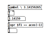
The backslash-escaped space before the pi digits stops Pd from truncating it.
 posted in technical issues
Large number representation in pd
@60hz double precision would solve the bit-depth issue, but the textual representation of numbers (floats) would also have to be changed to add precision. (I haven't checked if pd-double does this or not.. katja's page makes it seem like it does though)
here is her description from https://www.katjaas.nl/doubleprecision/doubleprecision.html :
You have probably noticed that single precision floats are represented in Pd with a maximum of 6 significant digits. This is done to hide inconsistencies like 33 * 0.3 = 9.900001, which happens when 7 decimal digits are shown. The limitation to 6 significant digits is however very annoying when we want to type or see large integers, like indexes of long audio buffers.
In calculations, Pd can use all integers from 0 to 2^24 = 16,777,216, over 16 million. Numbers with up to 8 decimal digits. But in the GUI, 1 million is shown in scientific notation as 1e+06. This scientific notation also uses a maximum of 6 significant digits. Therefore, the next representable number is 1.00001e+06, that is 1 million and 10. See below how the result of 2^20 is rounded in the GUI, as an example. The fact that numbers are also stored with patches this way, makes things worse. At 44100 Hz samplerate, one million samples is about 23 seconds - not at all that much. Longer audio buffers are allowed, but handling them in the GUI becomes tricky.
 posted in technical issues
Having lots of switches into Pd
@alexandros now pwm and digital output work fine, but when I try to merge with digital and analog inputs it goes wrong. the leds flicker randomly. If you remove the code below
// do input pins: flicker stops. :/
int outPins[3] = {2, 4, 7};

int pwmPins[6] = {3, 5, 6, 9, 10, 11};

// a global variable to hold which LED we want to control (either digital or PWM)
int channel = 0;

int inPins[2] = {12, 13};

int analogPins[8] = {0, 1, 2, 3, 4, 5, 6, 7};

void setup() {

   for (int i = 0; i < 3; i++) {
    pinMode(outPins[i], OUTPUT);
  }
    for (int i = 0; i < 6; i++) {
    pinMode(pwmPins[i], OUTPUT);
  }
    for(int i = 0; i < 2; i++) {
    pinMode(inPins[i], INPUT);
  }

  pinMode(A0, INPUT_PULLUP);
  pinMode(A1, INPUT_PULLUP);
  pinMode(A2, INPUT_PULLUP);
  pinMode(A3, INPUT_PULLUP);
  pinMode(A4, INPUT_PULLUP);
  pinMode(A5, INPUT_PULLUP);
  pinMode(A6, INPUT);
  pinMode(A7, INPUT);

//DEFAULT works with thermistors,
//INTERNAL with transitor thermostats
  analogReference(DEFAULT);

  Serial.begin(115200);

}

void loop() {

  //do output pins:

  if (Serial.available()) {
    static int temp;
    byte in = Serial.read();
    if (isDigit(in)) temp = temp * 10 + in - '0';
    else if (in == 'c') {
      channel = temp;
      temp = 0;
    }
    else if (in == 'd') {
      digitalWrite(outPins[channel], temp);
      temp = 0;
    }
    else if (in == 'p') {
      analogWrite(pwmPins[channel], temp);
      temp = 0;
    }
  }

  // do input pins:

Serial.print("analog"); // use "knobs" as a keyword so you can receive
  // the knob values as a list with a [r analog] in Pd
  for(int i = 0; i < 8; i++){
    unsigned int analogVal = analogRead (analogPins[i]);
    Serial.print(" "); // first print a white space to separate the "knob" keyword from the values
    // and the values from each other
    Serial.print(analogVal); // then  print the actual knob value
  }
  Serial.println(); // finally print a newline character to denote end of data for keyword "knobs"

  Serial.print("digital");
  for(int i = 0; i < 2; i++) {
    unsigned int digitalVal = digitalRead(inPins[i]);
    Serial.print(" ");
    Serial.print(digitalVal);
  }
  Serial.println();
}
 posted in I/O hardware diy
Having lots of switches into Pd
First of all, don't separate functions for reading the serial data, even if you want to read data for different kinds of stuff.
Combining digital with PWM pins should be sort of straight forward. Here's some example code:
int digitalPins[4] = {2, 4, 7, 10};
// use an array for all the pins of similar type, e.g. PWM pins, like below
int pwmPins[6] = {3, 5, 6, 9, 11, 12}; // can't remember the exact pin numbers with PWM, change accordingly

// a global variable to hold which LED we want to control (either digital or PWM)
int channel = 0;

void setup() {
  for (int i = 0; i < 4; i++) {
    pinMode(digitalPins[i], OUTPUT);
    pinMode(pwmPins[i], OUTPUT);
  Serial.begin(115200);
}

void loop() {
  if (Serial.available()) {
    static int temp;
    byte in = Serial.read();
    if (isDigit(in)) temp = temp * 10 + in - '0';
    else if (in == 'c') {
      channel = temp;
      temp = 0;
    }
    else if (in == 'd') {
      digitalWrite(digitalPins[channel], temp);
      temp = 0;
    }
    else if (in == 'a') {
      analogWrite(pwmPins[channel], temp);
      temp = 0;
    }
}
Check this code with Pd by sending messages of the type print $1c$2d for digital values and print $1c$2a for analog values. $1 is the led number (incrementing, starting from 0), and $2 is the value you want to write, 0-1 for digital and 0-255 for PWM.
posted in I/O hardware diy
Having lots of switches into Pd
@alexandros
This code sort of works with wip_multiple_PWM.pd
// merging works but pwm leds are choppy.

// number of elements in arrays need to
// match for() cycles in void setup and void loop
int pinsIn[2] = {2, 4};
int pinsAnalog[8] = {0, 1, 2, 3, 4, 5, 6, 7};

int pin = 0;
int val = 0;
int pinsOut[2] = {7, 12};

//TMP setup pwm:

// variables to hold pin numbers
int pwmLED1 = 3;
int pwmLED2 = 5;
int pwmLED3 = 6;
int pwmLED4 = 9;
int pwmLED5 = 10;
int pwmLED6 = 11;

// variables to hold pin states
int pwmLEDvalue1;
int pwmLEDvalue2;
int pwmLEDvalue3;
int pwmLEDvalue4;
int pwmLEDvalue5;
int pwmLEDvalue6;

//should this be omitted and use the a
// variable to hold and assemble incoming data
int temporary;

//END TMP pwm setup

void setup()
{
  //set up a total of pins for digital input (has to match number of elements in array)
  for(int i = 0; i < 2; i++)
  pinMode(pinsIn[i], INPUT);

  for (int i = 0; i < 2; i++) {
    pinMode(pinsOut[i], OUTPUT);
    digitalWrite(pinsOut[i], LOW);
  }

//DEFAULT works with thermistors,
//INTERNAL with transitor thermostats

  analogReference(DEFAULT);

  pinMode(A0, INPUT_PULLUP);
  pinMode(A1, INPUT_PULLUP);
  pinMode(A2, INPUT_PULLUP);
  pinMode(A3, INPUT_PULLUP);
  pinMode(A4, INPUT_PULLUP);
  pinMode(A5, INPUT_PULLUP);
  pinMode(A6, INPUT);
  pinMode(A7, INPUT);

//TMP test pwm setup:

  pinMode(pwmLED1, OUTPUT);
  pinMode(pwmLED2, OUTPUT);
  pinMode(pwmLED3, OUTPUT);
  pinMode(pwmLED4, OUTPUT);
  pinMode(pwmLED5, OUTPUT);
  pinMode(pwmLED6, OUTPUT);

  Serial.begin(115200); // perhaps use a faster baud rate
}

void loop()
{
  Serial.print("knobs"); // use "knobs" as a keyword so you can receive
  // the knob values as a list with a [r knobs] in Pd
  for(int i = 0; i < 8; i++){
    unsigned int knob = analogRead (pinsAnalog[i]);
    Serial.print(" "); // first print a white space to separate the "knob" keyword from the values
    // and the values from each other
    Serial.print(knob); // then  print the actual knob value
  }
  Serial.println(); // finally print a newline character to denote end of data for keyword "knobs"

  // the same technique applies to the switches too
  // receive the switch values as a list with [r switches]
  Serial.print("switches");
  for(int i = 0; i < 2; i++) {
    int switchVal = digitalRead(pinsIn[i]);
    Serial.print(" ");
    Serial.print(switchVal);
  }
  Serial.println();

  //handle digital outputs
  if (Serial.available()) {
    static int temp;
    byte in = Serial.read();
    if (isDigit(in)) {
      temp = temp * 10 + in - '0';
    }
    else if (in == 'p') {
      pin = temp;
      temp = 0;
    }
    else if (in == 'v')  {
      val = temp;
      temp = 0;
      digitalWrite(pinsOut[pin], val);
    }
}

//TMP merge test PWMs:
while(Serial.available()){
     byte inByte = Serial.read();
     if((inByte >= '0') && (inByte <= '9'))
       temporary = 10 * temporary + inByte - '0';
     else{
       if(inByte == 'p'){
         pwmLEDvalue1 = temporary;
         temporary = 0;
       }
       else if(inByte == 'q'){
         pwmLEDvalue2 = temporary;
         temporary = 0;
       }
       else if(inByte == 'r'){
         pwmLEDvalue3 = temporary;
         temporary = 0;
       }
       else if(inByte == 's'){
         pwmLEDvalue4 = temporary;
         temporary = 0;
       }
       else if(inByte == 't'){
         pwmLEDvalue5 = temporary;
         temporary = 0;
       }
       else if(inByte == 'u'){
         pwmLEDvalue6 = temporary;
         temporary = 0;
       }
     }
     analogWrite(pwmLED1, pwmLEDvalue1);
     analogWrite(pwmLED2, pwmLEDvalue2);
     analogWrite(pwmLED3, pwmLEDvalue3);
     analogWrite(pwmLED4, pwmLEDvalue4);
     analogWrite(pwmLED5, pwmLEDvalue5);
     analogWrite(pwmLED6, pwmLEDvalue6);
     //digitalWrite(dspLED, dspLEDstate);
   }
}
This is the code without PWM control. It works fine.
//number of elements in arrays need to match for() cycles in void setup
int pinsIn[4] = {6, 7, 8, 9};
int pinsAnalog[8] = {0, 1, 2, 3, 4, 5, 6, 7};

int pin = 0;
int val = 0;
int pinsOut[4] = {2, 3, 4, 5};

void setup()
{
  //set up a total of pins for digital input (has to match number of elements in array)
  for(int i = 0; i < 4; i++)
  pinMode(pinsIn[i], INPUT);

  for (int i = 0; i < 4; i++) {
    pinMode(pinsOut[i], OUTPUT);
    digitalWrite(pinsOut[i], LOW);
  }
//DEFAULT works with thermistors,
//INTERNAL with transitor thermostats
// ELLER var det tvartom???
  analogReference(DEFAULT);

  pinMode(A0, INPUT_PULLUP);
  pinMode(A1, INPUT_PULLUP);
  pinMode(A2, INPUT_PULLUP);
  pinMode(A3, INPUT_PULLUP);
  pinMode(A4, INPUT_PULLUP);
  pinMode(A5, INPUT_PULLUP);
  pinMode(A6, INPUT);
  pinMode(A7, INPUT);

  Serial.begin(115200); // perhaps use a faster baud rate
}

void loop()
{
  Serial.print("knobs"); // use "knobs" as a keyword so you can receive
  // the knob values as a list with a [r knobs] in Pd
  for(int i = 0; i < 8; i++){
    unsigned int knob = analogRead (pinsAnalog[i]);
    Serial.print(" "); // first print a white space to separate the "knob" keyword from the values
    // and the values from each other
    Serial.print(knob); // then  print the actual knob value
  }
  Serial.println(); // finally print a newline character to denote end of data for keyword "knobs"

  // the same technique applies to the switches too
  // receive the switch values as a list with [r switches]
  Serial.print("switches");
  for(int i = 0; i < 4; i++) {
    int switchVal = digitalRead(pinsIn[i]);
    Serial.print(" ");
    Serial.print(switchVal);
  }
  Serial.println();

  //handle digital outputs
  if (Serial.available()) {
    static int temp;
    byte in = Serial.read();
    if (isDigit(in)) {
      temp = temp * 10 + in - '0';
    }
    else if (in == 'p') {
      pin = temp;
      temp = 0;
    }
    else if (in == 'v')  {
      val = temp;
      temp = 0;
      digitalWrite(pinsOut[pin], val);
    }
}
}
and here is the code from tutorial5 from Arduino for Pd'ers. It goes with arduinoforpdrs_tut5.pd
// variables to hold pin numbers
int pwmLED = 9;
int dspLED = 2;
// variables to hold pin states
int pwmLEDvalue;
int dspLEDstate;
//variable to hold and assemble incoming data
int temporary;

void setup()
{
  pinMode(pwmLED, OUTPUT);
  pinMode(dspLED, OUTPUT);
  Serial.begin(9600);
}

void loop()
{
  while(Serial.available()){
    byte inByte = Serial.read();
    if((inByte >= '0') && (inByte <= '9'))
    temporary = 10 * temporary + inByte - '0';
    else{
      if(inByte == 'p'){
        pwmLEDvalue = temporary;
        temporary = 0;
      }
      else if(inByte == 'd'){
        dspLEDstate = temporary;
        temporary = 0;
      }
    }
    analogWrite(pwmLED, pwmLEDvalue);
    digitalWrite(dspLED, dspLEDstate);
  }
}
I am aiming at using same type of array handling as for the digital outs.
Thanks a lot
posted in I/O hardware diy
Using PD in a complex commercial hardware groovebox project
@ingox I remember it going the same slow route, but I could be wrong.
I think it has been around since at least 2007...... but maybe 2015..... I am usually wrong about everything.
New product release was much easier the further you go back in time......
It had more "save the planet" niche appeal when it started than full tech blowout I think (and they have built on that).
Niche can do it, but a user base is still a fundamental for sales, and will be smaller.
Organelle is certainly an established strong competition for a new entrant.
It was around in 2015.... https://forum.pdpatchrepo.info/topic/9570/organelle
and manufactured by an established synth company.... so they had the resources.
I was not 100% mistaken. Not the same principle, but the same design from 2009/2011.......
https://encyclotronic.com/synthesizers/critter-guitari/pocket-piano-r1216/
And they have done the "flashing buttons" too.......
https://encyclotronic.com/synthesizers/critter-guitari/critter-guitari-onda-musical-instrument-computer-r1792/
 posted in I/O hardware diy
How to detect a hit on the guitar strings (coming through [adc~]) and use it as a simple bang trigger
@toxonic Thank you very much for your help. Indeed you helped me out a lot with your suggestions, especially to use [bonk~].
[bonk~] is really good, since it allows me to learn specific signal patters (i.e., in my case the hit with the hand on guitar strings), and it is able to detect it in the followup microphone coming from the guitar.
This hit detection got really messy using the [fiddle~] or [sigmund~] since there was a need to filter the power in specific frequency ranges and the amplitude of certain frequencies when the very percussive hit on the guitar strings happens. The problem is really complex if one wants to discern the guitar strings hit during a regular guitar playing with many events happening at the same time.
 posted in patch~