ELSE 1.0-0 RC13 with Live Electronics Tutorial Released
Ok, the cat is out of the bag --> https://github.com/porres/pd-else/releases/tag/1.0-rc13 I'm officialy announcing the update and uploaded binaries to deken for mac (intel/arm), Win and Linux. It all looks ok but tell me if you see something funny please. There's also a raspberry pi binary but not working 100%yet and we'll still look into that. Hopefully someone could help me/us with it. I might make another upload just for the pi later on if/when we figure it out. Find release notes and changelog below.
RELEASE NOTES:
Please support me on Patreon https://www.patreon.com/porres I'll now try to add special content for subscribers. You can follow me on instagram as well if you like... I'm always posting Pd development stuff over there https://www.instagram.com/alexandre.torres.porres/
It's been a little bit over 7 months since the last update and I almost broke the record for taking too long to release an update (which had happened in my previous update). So yeah, there's just too much to talk about! I guess the delays in releasing updates is because it's been a little tricky and hard to sync the release cycles of ELSE with PlugData, which includes ELSE in its download.
Plugdata 0.9.2 should come out soon with ELSE RC13 and it's supposedly the last update before 1.0.0, so I've heard. And the plans was to get to that still in 2025! This means ELSE could be at its last "Release Candidate" phase as I'm aiming to sync the final release with PlugData. Until then, I'll still make breaking changes and I can't wait until I can't do that anymore as I really feel bad. On the other hand, it's kind of inevitable when I'm always adding new stuff and redesigning and reconfiguring objects to include more functionalities. And I always got a lot of new stuff! So I'm thinking that I will eventually try some mechanism like Pd's compatibility flag or something. I'll try to come up with something like that in the next update.
This update has 22 new objects for a total of 573 and 26 new examples in my tutorial for a total of 554 examples. Let's dive into the highlights (see full changelog below after the release notes).
-
Multichannel Support: Last release had 92 MC aware objects, now it's 139! Over a 50% increase that include old and new objects (all the new ones have been coming with MC support). Virtually all oscillators and envelope generators now have MC support, plus some other random ones. Let me highlight the new [lace~]/[delace~] objects that are 'MC' tools that perform interleave/deinterleave in Multichannel connections. My bare minimum number of objects "to start with" would be at least a bit over half the number of signal objects. That was my target for 1.0! ELSE right now has 319 signal objects, so that'd be at least 160. I will definitely pass this milestone in the next update. I guess a good number of MC objects would be around 75% of the signal objects. I will aim for that as soon as I can. Some objects simply can't be MC at all, so 100% will never be the case, but maybe an ideal 90% eventually? We'll see... I am just proud and happy that ELSE is taking such a big jump on MC awareness in less than a couple years.
-
Envelope generators ([adsr~]/[asr~]/[envgen~]/[function~]) now have more curve options. For [adsr~]/[asr~] the default is now a new log curve that you can set the curve parameter (and was 'stolen' from SuperCollider). A new [smooth~] family of objects perform the same kind of curved smoothening for alternating inputs - [envgen~] and [function~] also have that but also '1-pole' filtering, 'sine' and 'hann' curves. You can now trigger [adsr~] and [asr~] with impulses.
-
The [play.file~] object now supports even more file formats besides MP3 and stuff. Hey, you can even stream the supported formats from weblinks! The [sfload] object (which loads files into arrays) also gained support for more formats and can download from weblinks as well! It also has a new threaded mode, so loading big files won't choke Pd. It now also outputs the file information, which is a way to tell you when loading finished in threaded mode. The [sample~], [player~], [gran.player~] and [pvoc.player~] objects are now also based on [sfload], so they support all these file formats!!! Now [sample~] and [tabplayer~] are integrated in a way that [tabplayer~] is always aware of the sample rate of the file loaded in [sample~] (so it reads in the "correct speed"). A new [sfinfo] object is able to extract looping regions and instrument metadata information from AIFF files (which is something I wanted for ages) - it should do more stuff in the future.
-
[knob] has become the ultimate featured bloated creep GUI I always feared and avoided. MAX is envy! but I'm happy with this structure and I want to replicate in other GUIs in the future (yeah, I got plans to offer alternatives to all iemguis). I wanna highlight a new 'param' symbol I added that allows you to remotely set a particular method in an object, so you don't to connect to a "method $1" message and you can even do this wirelessly with a send symbol. [knob] now also acts like a number box, where you can type in the value, which may also be displayed in different ways or the value can be sent elsewhere via another send symbol so you can temper with it using [makefilename] or [else/format]. I've been using this for the MERDA modules and it's really cool.
-
We finally have a [popmenu] GUI object! This was in my to do list forever and was crucial to improve the MERDA modules to set waveforms, instruments and whatnot.
-
Let's about MERDA, the "Modular Euroracks Dancing Along" subset of abstractions in ELSE. It was first released in the last update and it's been driving lots of the development in ELSE as you can see. I now added a MIDI Learn feature for all knobs that feels great and quite handy! There are many fixes and improvements in general and some new modules. I wanna highlight the new [sfont.m~] module, which loads "sound font" banks and you can just click on a [popmenu] to choose the instrument you want. The default bank has numerous (hundreds) options and also comes with PlugData. The sequencer module [seq8.m~] was rather worthless but it's now a whole new cool thingie. It allows you to set pitches with symbols and even has quarter tone resolution. I added a right outlet to send impulses to trigger envelopes and stuff (there's still more stuff of course, see full changelog below).
-
There are newly designed/renamed/recreated [resonbank~]/[resonbank2~] objects that are well suited for Modal Synthesis.
-
What actually drives my development is my Live Electronics tutorial, which got a fair upgrade with a new chapter on Modal Synthesis amongst other things, such as new subtractive synthesis examples and a revision of envelope generators with examples on AHDSR and DAHDSR - by the way, there are new gaterelease~/gatedelay~ objects for handling envelopes (and other processes).
-
I have to thank some people. Tim added 'zoom' to the [pic] object, as well as an image offset. Tim also implemented a new and better technique for bandlimited oscillators. Ben Wesh gave me a new [scope3d~] GUI object, pretty cool, that plots an oscilloscope in 3 dimensions, which is coded in LUA - and ELSE has been carrying a modified version of [pdlua] because it now depends on it for a couple of GUIs. Tim and Ben made many improvements to [pdlua] (as well as Albert Graef, of course).
-
For more new objects, let me also tell you about the simple and cool [float2imp~], that is based on [vline~] and can convert floats to impulses with sample accuracy (don't know why I didn't think of that earlier). A new [tanh~] object has Multichannel support. A bit earlier I made an update to Cyclone that actually "borrows" and includes this one from ELSE instead of its original one (which does not have Multichannel support). PlugData users will load the one from ELSE. This is another tiny step that sort of integrates ELSE and Cyclone, specially for PlugData users.
happy patching.
CHANGELOG:
LIBRARY:
Breaking changes:
- [adsr~]/[asr~]: now a gate off before reaching the sustain point does not start the release right away (this allows you to trigger it with impulses). There's a new mode just for immediate release. There's a new exponential setting for curve factors, the old 'log' mode is renamed to 'lag' as it's the same as used in the [lag~] object. For [adsr~], a bang now is not "retrigger", but an impulse at control rate, there's a new 'retrigger' message for control rate retriggering (and now it only retriggers if the gate is on). For [asr~] a bang now also works like an impulse.
- [sample~]: no more 'load' message, args to 'open' message changed, size is now only in 'ms'.
- [format]: outputs are now always symbols, before you could get float outputs. Also, we just have a simplified symbol output, no more lists or anythings. Hopefully I'll be able to get the 'list' output back, but it involved some bugs that I couldn't fix so I just removed it. You cannot use bangs and lists in secondary inlets no more (this is cylone/max crappy paradigm we don't want here). Bang method was actually removed as well.
- [pack2]: no more support for anythings, also no more support for lists in secondary inlets and output has a list selector (I wanna make this more Pd like and not a silly clone from MAX's [pak], cause fuck MAX).
- [merge]/[unmerge]/[group]: no more '-trim' flag (again, respecting pd's usual list paradigm), in [merge] now there's no more 'hot' argument and a bang now represents an empty list and inlets initialized with empty lists
- [mono]: 1st argument is now 'glide' in ms.
- [sfont~] now uses 'mma' for bank selection (this alters how CC messages set the bank number).
- [player~]/[play.file~]: 'open' message does not play files right away anymore.
- [tabplayer~]/[player~]: play message without args now play at the default settings (whole file at regular speed).
- [envgen~]: removed the 'maxsustain' parameter, use the new [gaterelease~] or [gaterelease] objects instead. Removed the rightmost inlet just to set envelopes, now a list input only sets the envelope and doesn't trigger it. The 'set' message is then removed.
- [envgen~]/[function~]: simplified and got rid of '-exp' flag and message, also deleted 'expl' and 'expi' messages. A new 'curve' and cimpler message sets exponential factors for all or individual segments, and includes more curve formats.
- [knob]: 'esc' key now deactivates the object. The 'ticks' message is renamed to 'steps' and there is a new 'ticks' message that toggles showing ticks on and off. The 'start' message has been renamed to 'arcstart'. The 'outline' message has been renamed to 'square' for better clarity. Design changed a bit to make it like it is in PlugData (they won), so we now fill the whole background color when in 'square mode' and the knob circle has an 85% proportion in this case inside the full 100% square size (so it grows bigger when not in 'square' mode). Now, by default, the GUI is in a new 'loadbang' mode (I don't think this will influence old patches). I'm afraid some old patches might behave really weird since I added a lot of new stuff. I changed the 'load' message behaviour to not update the object (this can arguably be considered a bug fix).
- [wavetable~], [bl.wavetable~] and [wt2d~]: 'set' message now sets frequencies because of the MC support in [wt~] and [wt2d~], while there's a new 'table' method to set the table name.
- [gbman~]/[cusp~] list method is now for MC, old list method is now renamed back to an old 'coeffs' method.
- [f2s~]/[float2sig~] default value is now 10 ms.
- [op] now behaves like [*~] where the smaller list wraps til reaching the size of the longer one.
- [list.seq] does not loop anymore by default.
- [impseq~] list input removed, use the new [float2imp~] object to convert floats to impulses.
- [resonant~] now has 'q' as the default.
- [resonant2~] has been removed.
- [decay2~] has also been removed ([asr~] much better).
- [vcf2~] has been renamed to [resonator2~].
- [resonbank~]/[resonbank2~] have basically been deleted and replaced by new objects with the same name... [resonator~] is based on a new [resonator~] object which is similar to [resonant~] and [resonbank2~] is now based on [resonator2~] (old [vcf2~] instead of [resonant2~] that got deleted). These are well suited objects for Modal Synthesis.
- [oscbank~] now uses a 'partial' list and not a frequency list. The freq input now defaults to '1' and this makes [oscbank2~] completely obsolete.
- [oscbank2~] has been deleted since it became completely obsolete.
- [sfload] load message changed the behaviour a bit.
Enhancements/fixes/other changes:
- [adsr~]: We have now a new mode for immediate release (see breaking changes above, I'm not repeating it). Fixed ADSR signal inputs (it was simply not really working, specially for linear). Fixed status output for MC signals. There's a new curve parameter that allows you to set the curvature.
- [asr~] I actually just made the new [adsr~] code into a new [asr~] code as a simplified version (as it was before)... so it's got the same impromevents/fixes.
- [play.file~]: added support for more file formats and even weblinks for online streaming!
- [sfload]: added an outlet to output information, added threaded mode, added support for more file formats and even weblinks for downloading.
- [sample~], [player~], [gran.player~] and [pvoc.player~] are now also based on [sfload], so they support more file formats!
- [sample~]: improved extension management with [file splitext].
- [sample~] and [tabplayer~] now are automatically integrated in a way that [tabplayer~] is always aware of the sample rate of the file loaded in [sample~], so it automatically adjusts the reading speed if it is different than the one Pd is running with.
- [numbox~]'s number display is not preceded by "~" anymore (that was just kinda stupid to have).
- [format]: fixed issues where empty symbols and symbols with escaped spaces didn't work. Added support '%a' and '%A' type. Added support for an escaped 'space' flag. Improved and added support for length modifiers. Improved syntax check which prevents a crash. Improved documentation.
- [knob]: added new 'param', 'var', 'savestate', 'read only', 'loadbang', "active", "reset" and 'ticks' methods. Added the possibility to type in number values and also modes on how to display these number values, plus new send symbols for 'activity', 'typing', 'tab' and 'enter'. New design more like plugdata. Changed some shortcuts to make it simpler. If you have the yet unreleased Pd 0.56-0 you can also use 'double clicking' in the same way that works in PlugData. Properties were also significantly improved (I'm finally starting to learn how to deal with this tcl/tk thingie). Yup, a lot of shit here...
- [autofade2~]/[autofade2.mc~]: fixed immediate jump up for 0 ramp up.
- [synth~]: fixed polyphony bug.
- [metronome~]: fixed bug with 'set' message.
- [midi2note]: fixed range (octaves 0-8).
- [pulsecount~]: fixed reset count to not output immediately, added bang to reset counter at control rate
- [click]: fixed regression bug where it stopped working.
- [else]: new 'dir' method to output ELSE's binary directory in a new rightmost outlet. The print information also includes the directory.
- [pic]: added zoom capability finally (thanks to tim schoen) and added offset message (also thanks to tim).
- [store]: added 'sort' functionality.
- [scales]: fixed octave number argument. Added functionality to allow octave number as part of the note symbol.
- [mono]: added 'glide' parameter, as in [mono~].
- [pluck~]: fixed list input.
- [rescale]/[rescale~]: added a "reverse log" mode.
- [limit]: added a new second ignore mode.
- [graph~]: added an external source input for plotting the graph and a 'clear' message.
- [canvas.setname]: added a new argument for "abstraction mode" and methods to set name, depth (and mode).
- [midi.learn]: added a new argument for "abstraction mode", fixed 'dirty' message sent to parent.
- [brickwall~]: fixed initialization.
- [list.seq]: added a loop mode and a 2nd outlet to send a bang when the sequence is done.
- [delete]: fixed index for positive numbers.
- [dust~]: added 'list', 'set' and '-mc' flag for managing the already existing Multichannel capabilities.
- Thanks to Tim we have many fixes and a whole new technique for band limited oscillators. Now [bl.saw~], [bl.saw2~], [bl.vsaw~], [bl.square~], [bl.tri~], [bl.imp~] and [bl.imp2~] have been redesigned to implement elliptic blep, which should provide better anti-aliasing.
- [parabolic~] now uses and internal wavetable for more efficiency.
- [resonant~]: added 'bw' resonance mode.
- [lowpass~]/[highpass~]: added 't60' resonance mode.
- [quantizer~]/[quantizer]: added a new mode, which combines floor (for negative) and ceil (for positive) values.
- [crusher~]: now uses the new [quantizer~] mode from above (arguably a breaking change).
- [envgen~]: fixed a bug (actually a misconception) where ramps started one sample earlier. Fixed 0-length lines. Added a possibility to set time in samples instead of ms. Maximum number of lines is now 1024. Added loop mode. Added many curve options (sin/hann/log curve/lag).
- [function~]: Added many curve options (sin/hann/log curve/lag).
- [The out~] family of abstractions now use [bitnormal~] so you won't blow your speakers beyond repair in edge cases.
- [trig.delay~]/[trig.delay2~]: fixed bug where impulse values different than '1' didn't work.
- Added MC support to: [trig.delay~], [trig.delay2~], [gatehold~], [vca.m~], [gain2~], [decay~], [asr~], [envgen~], [function~], [bl.osc~], [bl.saw~], [bl.saw2~], [bl.vsaw~], [bl.square~], [bl.tri~], [bl.imp~], [bl.imp2~], [imp2~], [tri~], [saw~], [saw2~], [vsaw~], [square~], [pulse~], [parabolic~], [gaussian~], [wavetable~], [wt2d~], [randpulse~], [randpulse2~], [stepnoise~], [rampnoise~] [pink~], [gbamn~], [cusp~], [gray~] and [white~].
- Also added MIDI input and soft sync to [imp2~], [tri~], [saw~], [saw2~], [vsaw~], [square~], [pulse~], [gaussian~] and [parabolic~].
- [wavetable~] and [wt2d~] gained args to set xfading.
- Updated pdlua to 0.12.23.
- M.E.R.D.A: Added MIDI-LEARN for all modules (this is only for the knobs). Replaced some number boxes that were attached to knobs by an internal number display mechanism (new feature from knob). Improved interface of [gendyn.m~]. Preset/symbol name fixes to [flanger.m~]. Now we have automatic MIDI mode detection for [plaits.m~] and [pluck.m~] when no signals are connected (still trying to get plaits right, huh? Yup! And bow MIDI input with monophony and trigger mode has been fixed in [plaits.m~]). Added MC support to [vca.m~]. Increased range of [drive.m~] down to 0.1. Changed some objects to include the new [popmenu] GUI. [vco.m~] now uses the new MC functionalities of oscillators and doesn't need to load abstractions into [clone], I hope it makes this more efficient and clean. The [seq8.m~] module was worthless and got a decent upgrade, it's practically a new module. Added new modules (see below). Note that MERDA is still at alpha development phase, much experimental. Expect changes as it evolves.
- 22 new objects: [float2imp~], [lace], [delace], [lace~], [delace~], [gatehold], [gatedelay],[gatedelay~], [gaterelease~], [gaterelease], [popmenu], [scope3d~], [tanh~], [resonator~], [sfinfo], [smooth], [smooth2], [smooth~], [smooth2~], [dbgain~], [level~] plus [crusher.m~], [sfont.m~] and [level.m~] MERDA Modules.
Objects count: total of 573 (319 signal objects [139 of which are MC aware] and 254 control objects)!
- 323 coded objects (210 signal objects / 113 control objects)
- 227 abstractions objects (87 signal objects / 140 control objects)
- 23 MERDA modular abstractions (22 audio / 1 control)
TUTORIAL:
- New examples and revisions to add the new objects, features and breaking changes in ELSE.
- Added the MERDA modules into the examples for reference.
- Revised section on envelopes.
- New subtractive synthesis examples.
- New chapter on Modal Synthesis.
- Total number of examples is now 554! (26 new ones)
 posted in news
Coarse-grained noise?
@jameslo Oh, [expr~] obviously can't handle this kind of pow notation ... So what I suggested (pretty arbitrarily, to be honest) was just a skinny Gaussian curve. Try exp(-1000*$v1*$v1) instead.
The intuition behind my choice was quite simple: First off, I thought it might be useful to reduce the density of the echoes of the input sample. In fact, convolution does produce "echoes" at every sample, although most of them won't be heard as echoes but as filtering effects. Furthermore, the exponential function has the useful property to be bounded between 0 and 1 for negative input values, and it seemed to be a natural choice, since it corresponds to our perception of amplitude.
Trying to generalize on how to use a transfer/shaping function in this specific case: The input (noise) is equally distributed, so the distribution of the output will be exactly the same as the distribution of the shaping function itself. If I correctly understand the concept of white noise, any shaping function will also produce white noise as its output. The "color" of noise is only affected, if the operation introduces some kind of correlation between successive samples. That's what all digital filters do, of course. So now you may ask: Then why does waveshaping in its conventional use affect the timbre of a sound? Well, usually successive samples of an input signal aren't uncorrelated, right? A transfer/shaping function then will have some impact on the existing autocorrelation of the sound. So the case of applying such a function to white noise is really quite specific.
BTW: Thinking about distributions of sample values also helps to understand the RMS amplitude of differently distributed white noise signals: Equally distributed noise has the same power as triangle and sawtooth waves, whereas binary noise has the greatest possible power, equal to square waves etc.
Hopefully, this does help in some way ... Apart from that, I would recommend to implement the transfer function as a lookup table and draw different curves. I think, this might be the best way to get an intuition of how a waveshaping transfer function works.
Edit: Drawing the histogram instead of the transfer function may be even more intuitive, especially if you already know how to use [array random]. So here's basically an audio rate version of that ... array_random~.pd
 posted in technical issues
Coarse-grained noise?
@whale-av Judging from your reply I think I could have asked my question more clearly. I'm simply applying a impulse-response (IR) reverb to a piano chord, and IR reverbs use convolution under the hood. In this case though I'm using an artificial impulse response, stereo white noise, which is like simulating a 100% reverberant space that has a 30s hang time during which the reverb does not decay. In such a strange space, if you could go in and pop a balloon, it would give you 30s of white noise back.
Changing the noise color is not what I need. Darker noise just creates darker reverb, one with less high frequency energy. I need a different kind of white noise if such a thing exists. Something bumpy, coarse-grained.
The volume variation I'm referring to is analogous to watching a real-time analyzer (RTA) while playing noise through a sound system. Each of the frequency band strengths bounce around a bit--that's the variation. I'm wondering if I make noise that would cause an RTA to bounce around like crazy whether that noise, when used as an IR, would cause my piano chord (or whatever) to sound even more tremolo-ish.
I did a little FFT analysis on [noise~] and found that while the phase angle of each term appears randomly and equally distributed, the modulus has a bell-curve distribution that favors smaller moduli. Ah ha! Evidence that certain frequencies are popping out from moment to moment. I tried using [array random] to synthesize similar distributions of moduli together with completely randomized phases but the result was disappointing. The noise sounds like a low fidelity mp3 and when used as an IR it increases the tremolo effect only slightly, if at all. Next, I tried resynthesizing [noise~] by subtracting an amount from each modulus, multiplying it back up to match the former peak, and then [clip~ 0 1e+09]. The result sounds like nasty digital noise but as an IR is just as smooth as [noise~] itself. I did both experiments using [block~ 1024 2 1] and a plain cosine window (like what you might use in a granular synth) hoping to lengthen each frequency peak. <--probable BS alert.
Returning to time domain, I then tried filtering noise through something like a 64 band 1/5 oct graphic EQ with rapidly changing random band cut amounts up to 12dB. When used as an IR, the result gives a strong but unnatural effect.
So far the best noise I've generated (for use as an IR) is to take some real-world steady-ish sound, like a bubbling cauldron, and to "whiten" it by using the technique in I05.compressor. The result sounds awful but that surprisingly doesn't mean it's not useful as an IR. I've got a lot more investigation to do, but if anyone is curious about the view from down here in the weeds I'd be happy to post snapshots, patches and sound files.
 posted in technical issues
How to keep number until turn knob
it gets in the weeds - basically you got a problem if your knob isn't a digital encoder which sends things like +1 or -1 to move numbers - typically these also have a push button.
if your knob is a potentiometer/slider/knob/pot like on an electric guitar - these only give discrete values and will Jump like on the left.
if you use one of those like I am on the right - and I apologize for it seeming messy, I'm cleaning up little problems - but the knob is still a potentiometer, so even tho I changed it into something that compares if its going higher or lower it ends up at weird places - so to do it right these needs to be an encoder type of knob - (which I'm simulating by just hitting the 1 and -1, a little surprised acting like an encoder isn't in [knob] yet.)knob-problems-pot-vs-encoder.pd
 posted in technical issues
Midi Rotary Knob Direction Patch/Algorythm?
Hey everybody,
Sorry, for a lot of text. But the bold text at the bottom is my main question. The rest will help you to get a better understanding of my situation.
you helped me so much, with my last question here (the Faders are working dope now):
https://forum.pdpatchrepo.info/topic/13849/how-to-smoothe-out-arrays/25
I am doing a Steinberg Houston to Mackie Control emulation at the moment, to use my controller with other DAWs than Cubase/Nuendo. Will upload it to the internet community, when I am finished for the handful of people that maybe are also using this controller.
I made good progress:
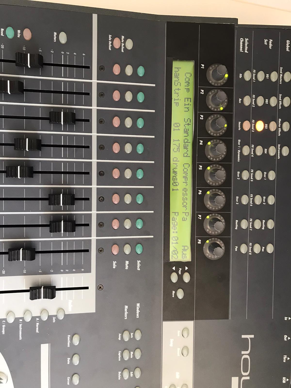
I got the Faders and the normal knobs to work. And the display puts out information. But it is with bugs, because the LCD Screen of the Houston has 40 characters for one line and the Mackie Universal Pro has 56 Characters. So i did a list algorithm, which deletes spaces of the mackie message until the message fits on the 40 character line. Maybe there is a method wich will work better but this subject eats too much time for me at the moment and it works rough okay. One defenitely get's some helpful information on the screen from the DAW.
The Faders and Rotary Knobs and normal knobs are the most important of this controller I guess. The Faders are working fine as I mentioned above, but there is a problem with the rotary knobs, wich I can't handle alone and hope you can help me. 
The problem is, that the Mackie Controller send simple clicks to the DAW. If you are turning a rotary knob, it sends out a number of midi messages:
If you turn it right, it sends midi messages wich contains the value 1 and if you turn it down it sends messages wich are containing the value 65.
"When the VPots are rotated rapidly, a message equal to the number of clicks is sent."
BUT the Houston controller instead is sending values like it's faders with 15 (MSB) and 128(LSB) values. AND it is updating the rotary limit by itself. So if I turn a rotary, it will update it's LEDs and stops sending midi messages when it reaches the maximum or minimum value. So, I did this patch as a momentary state:
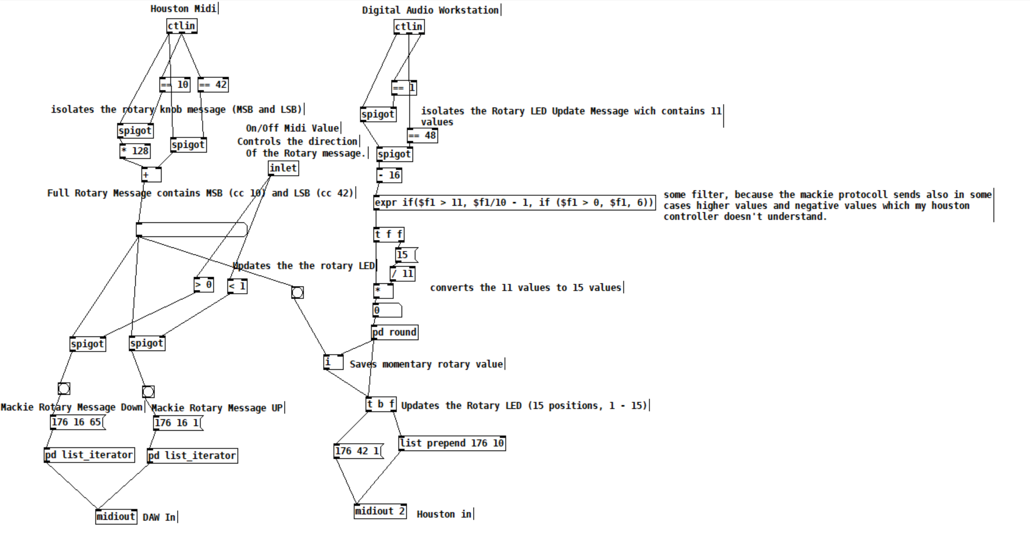
The DAW sends 11 values for the Houston LEDs. 11 is max and 1 is min. This is good, I send this values to my houston controller and can update the rotary values and LEDs.
With this updated values from the DAW, I can force my rotary knobs, that they don't stop to send values, because they are set to the values, which the DAW sends, every time I turn a knob. With this method I got it to work to imitate a Mackie Rotary knob. Everytime the Houston Rotary value changes, it sends Mackie "midi click values" according to the amount of midi value changes of the houston.
BUT the problem is, that this is working only in one direction. Now my main question:
How can I make pure Data know, if I am turning my knob in the left direction or in the right direction? There is also the problem, which I mentioned above, that I set the momentary value everytime, I move the rotary, so that I get a unlimited amount of possible rotary move "clicks". Also the midi values which the houston sends arent perfect smooth. It works fine, but it isn't like that, that if you move a rotary in one direction, every value one by another is perfectly lower or higher.
I think I maybe need a algorythm, which looks if the values in a time period are getting higher or lower and then send out bangs on two seperate outlets. For example the left outlet for lower values and the right outlet for higher values. And it should also detect, if I move the rotary fast or slow. So a constant smoothing or clocked bang is also not an option. This is defenitely to complicated for me. I have no idea and what I tried didn't worked.
Would be super cool, if you could help me out again. 
 posted in technical issues
Having lots of switches into Pd
@alexandros
This code sort of works with wip_multiple_PWM.pd
// merging works but pwm leds are choppy.

// number of elements in arrays need to
// match for() cycles in void setup and void loop
int pinsIn[2] = {2, 4};
int pinsAnalog[8] = {0, 1, 2, 3, 4, 5, 6, 7};

int pin = 0;
int val = 0;
int pinsOut[2] = {7, 12};

//TMP setup pwm:

// variables to hold pin numbers
int pwmLED1 = 3;
int pwmLED2 = 5;
int pwmLED3 = 6;
int pwmLED4 = 9;
int pwmLED5 = 10;
int pwmLED6 = 11;

// variables to hold pin states
int pwmLEDvalue1;
int pwmLEDvalue2;
int pwmLEDvalue3;
int pwmLEDvalue4;
int pwmLEDvalue5;
int pwmLEDvalue6;

//should this be omitted and use the a
// variable to hold and assemble incoming data
int temporary;

//END TMP pwm setup

void setup()
{
  //set up a total of pins for digital input (has to match number of elements in array)
  for(int i = 0; i < 2; i++)
  pinMode(pinsIn[i], INPUT);

  for (int i = 0; i < 2; i++) {
    pinMode(pinsOut[i], OUTPUT);
    digitalWrite(pinsOut[i], LOW);
  }

//DEFAULT works with thermistors,
//INTERNAL with transitor thermostats

  analogReference(DEFAULT);

  pinMode(A0, INPUT_PULLUP);
  pinMode(A1, INPUT_PULLUP);
  pinMode(A2, INPUT_PULLUP);
  pinMode(A3, INPUT_PULLUP);
  pinMode(A4, INPUT_PULLUP);
  pinMode(A5, INPUT_PULLUP);
  pinMode(A6, INPUT);
  pinMode(A7, INPUT);

//TMP test pwm setup:

  pinMode(pwmLED1, OUTPUT);
  pinMode(pwmLED2, OUTPUT);
  pinMode(pwmLED3, OUTPUT);
  pinMode(pwmLED4, OUTPUT);
  pinMode(pwmLED5, OUTPUT);
  pinMode(pwmLED6, OUTPUT);

  Serial.begin(115200); // perhaps use a faster baud rate
}

void loop()
{
  Serial.print("knobs"); // use "knobs" as a keyword so you can receive
  // the knob values as a list with a [r knobs] in Pd
  for(int i = 0; i < 8; i++){
    unsigned int knob = analogRead (pinsAnalog[i]);
    Serial.print(" "); // first print a white space to separate the "knob" keyword from the values
    // and the values from each other
    Serial.print(knob); // then  print the actual knob value
  }
  Serial.println(); // finally print a newline character to denote end of data for keyword "knobs"

  // the same technique applies to the switches too
  // receive the switch values as a list with [r switches]
  Serial.print("switches");
  for(int i = 0; i < 2; i++) {
    int switchVal = digitalRead(pinsIn[i]);
    Serial.print(" ");
    Serial.print(switchVal);
  }
  Serial.println();

  //handle digital outputs
  if (Serial.available()) {
    static int temp;
    byte in = Serial.read();
    if (isDigit(in)) {
      temp = temp * 10 + in - '0';
    }
    else if (in == 'p') {
      pin = temp;
      temp = 0;
    }
    else if (in == 'v')  {
      val = temp;
      temp = 0;
      digitalWrite(pinsOut[pin], val);
    }
}

//TMP merge test PWMs:
while(Serial.available()){
     byte inByte = Serial.read();
     if((inByte >= '0') && (inByte <= '9'))
       temporary = 10 * temporary + inByte - '0';
     else{
       if(inByte == 'p'){
         pwmLEDvalue1 = temporary;
         temporary = 0;
       }
       else if(inByte == 'q'){
         pwmLEDvalue2 = temporary;
         temporary = 0;
       }
       else if(inByte == 'r'){
         pwmLEDvalue3 = temporary;
         temporary = 0;
       }
       else if(inByte == 's'){
         pwmLEDvalue4 = temporary;
         temporary = 0;
       }
       else if(inByte == 't'){
         pwmLEDvalue5 = temporary;
         temporary = 0;
       }
       else if(inByte == 'u'){
         pwmLEDvalue6 = temporary;
         temporary = 0;
       }
     }
     analogWrite(pwmLED1, pwmLEDvalue1);
     analogWrite(pwmLED2, pwmLEDvalue2);
     analogWrite(pwmLED3, pwmLEDvalue3);
     analogWrite(pwmLED4, pwmLEDvalue4);
     analogWrite(pwmLED5, pwmLEDvalue5);
     analogWrite(pwmLED6, pwmLEDvalue6);
     //digitalWrite(dspLED, dspLEDstate);
   }
}
This is the code without PWM control. It works fine.
//number of elements in arrays need to match for() cycles in void setup
int pinsIn[4] = {6, 7, 8, 9};
int pinsAnalog[8] = {0, 1, 2, 3, 4, 5, 6, 7};

int pin = 0;
int val = 0;
int pinsOut[4] = {2, 3, 4, 5};

void setup()
{
  //set up a total of pins for digital input (has to match number of elements in array)
  for(int i = 0; i < 4; i++)
  pinMode(pinsIn[i], INPUT);

  for (int i = 0; i < 4; i++) {
    pinMode(pinsOut[i], OUTPUT);
    digitalWrite(pinsOut[i], LOW);
  }
//DEFAULT works with thermistors,
//INTERNAL with transitor thermostats
// ELLER var det tvartom???
  analogReference(DEFAULT);

  pinMode(A0, INPUT_PULLUP);
  pinMode(A1, INPUT_PULLUP);
  pinMode(A2, INPUT_PULLUP);
  pinMode(A3, INPUT_PULLUP);
  pinMode(A4, INPUT_PULLUP);
  pinMode(A5, INPUT_PULLUP);
  pinMode(A6, INPUT);
  pinMode(A7, INPUT);

  Serial.begin(115200); // perhaps use a faster baud rate
}

void loop()
{
  Serial.print("knobs"); // use "knobs" as a keyword so you can receive
  // the knob values as a list with a [r knobs] in Pd
  for(int i = 0; i < 8; i++){
    unsigned int knob = analogRead (pinsAnalog[i]);
    Serial.print(" "); // first print a white space to separate the "knob" keyword from the values
    // and the values from each other
    Serial.print(knob); // then  print the actual knob value
  }
  Serial.println(); // finally print a newline character to denote end of data for keyword "knobs"

  // the same technique applies to the switches too
  // receive the switch values as a list with [r switches]
  Serial.print("switches");
  for(int i = 0; i < 4; i++) {
    int switchVal = digitalRead(pinsIn[i]);
    Serial.print(" ");
    Serial.print(switchVal);
  }
  Serial.println();

  //handle digital outputs
  if (Serial.available()) {
    static int temp;
    byte in = Serial.read();
    if (isDigit(in)) {
      temp = temp * 10 + in - '0';
    }
    else if (in == 'p') {
      pin = temp;
      temp = 0;
    }
    else if (in == 'v')  {
      val = temp;
      temp = 0;
      digitalWrite(pinsOut[pin], val);
    }
}
}
and here is the code from tutorial5 from Arduino for Pd'ers. It goes with arduinoforpdrs_tut5.pd
// variables to hold pin numbers
int pwmLED = 9;
int dspLED = 2;
// variables to hold pin states
int pwmLEDvalue;
int dspLEDstate;
//variable to hold and assemble incoming data
int temporary;

void setup()
{
  pinMode(pwmLED, OUTPUT);
  pinMode(dspLED, OUTPUT);
  Serial.begin(9600);
}

void loop()
{
  while(Serial.available()){
    byte inByte = Serial.read();
    if((inByte >= '0') && (inByte <= '9'))
    temporary = 10 * temporary + inByte - '0';
    else{
      if(inByte == 'p'){
        pwmLEDvalue = temporary;
        temporary = 0;
      }
      else if(inByte == 'd'){
        dspLEDstate = temporary;
        temporary = 0;
      }
    }
    analogWrite(pwmLED, pwmLEDvalue);
    digitalWrite(dspLED, dspLEDstate);
  }
}
I am aiming at using same type of array handling as for the digital outs.
Thanks a lot
 posted in I/O hardware diy
looking for velvet noise generator
@porres oh yeah I always forget about [expr~] for some reason.. maybe bc of the license it used to have.
There's no real reason to have the phase reset inlet, just more control.
From what I can tell, velvet noise is outputting a 1-sample impulse of value that's either 1 or -1, chosen randomly, at a random point in a regular period.
So I have a [phasor~] to keep track of the period, and the [samphold~] samples a random value from 0-1 when the [phasor~] resets. This will be the point in the phase of that period that the impulse will occur. When the [phasor~] gets to above or equal to this value, the [<~ ] will go from 1 to 0. That goes into [rzero~ 1], which will put out a -1 on the sample that occurs. That goes into the [==~ -1], which acts (together with [*~ ]) as a gate for the noise value that has been manipulated to either be 1 or -1, depending on if the output of [noise~] is positive or not.
The issue with this original implementation was that when the [phasor~] wraps around to start a new phase, it can wrap to a value greater than the new [samphold~] value from the noise. That means that if the noise value is very small, there will be no impulse for that period since the [phasor~] value will never be less than the sampled noise value for that period (and therefore the [<~ ] won't go from 1 to 0, which means the [rzero~ 1] below it won't output a -1, and so on). So, the [rzero~] and [<~ 0] put out a 1-sample value of 1 when the [phasor~] wraps around, which is combined with the other signal in [min~ 1] to take care of this. That way the [rzero~ 1] below the [min~ 1] will get a 1 even if the wrapped-around [phasor~] value is less than the new sampled noise value, and there will be an impulse for that period.
(that is what "make sure there is at least 1 1 on wraparound" means)
edit: after writing all of this it occurred to me that the sampled noise value could also be greater than the value that the [phasor~] will get to before it wraps around.. perhaps the solution is to constrain the sampled noise value depending on the frequency and phase of the [phasor~]...
 posted in technical issues
Having lots of switches into Pd
@alexandros thanks, it all works!
I merged the codes for in and outs and also changed so you can set up all of the pins with arrays (as you did in the latter code). Then you can set up the pins in any order.
Here is the Arduino code. Do you spot any errors I may have introduced?
//number of elements in array need to match for() cycles
int pinsIn[4] = {2, 7, 10, 11};
int pinsAnalog[3] = {0, 2, 3};

int pin = 0;
int val = 0;
// some random pins
int pinsOut[4] = {3, 4, 5, 6};

void setup()
{
  //set up a total of pins for input (has to match number of elements in array)
  for(int i = 0; i < 4; i++)
  pinMode(pinsIn[i], INPUT);

  for (int i = 0; i < 4; i++) {
    pinMode(pinsOut[i], OUTPUT);
    digitalWrite(pinsOut[i], LOW);
  }

  Serial.begin(115200); // perhaps use a faster baud rate
}

void loop()
{
  Serial.print("knobs"); // use "knobs" as a keyword so you can receive
  // the knob values as a list with a [r knobs] in Pd
  for(int i = 0; i < 3; i++){
    unsigned int knob = analogRead (pinsAnalog[i]);
    Serial.print(" "); // first print a white space to separate the "knob" keyword from the values
    // and the values from each other
    Serial.print(knob); // then  print the actual knob value
  }
  Serial.println(); // finally print a newline character to denote end of data for keyword "knobs"

  // the same technique applies to the switches too
  // receive the switch values as a list with [r switches]
  Serial.print("switches");
  for(int i = 0; i < 4; i++) {
    int switchVal = digitalRead(pinsIn[i]);
    Serial.print(" ");
    Serial.print(switchVal);
  }
  Serial.println();

  //handle digital outputs
  if (Serial.available()) {
    static int temp;
    byte in = Serial.read();
    if (isDigit(in)) {
      temp = temp * 10 + in - '0';
    }
    else if (in == 'p') {
      pin = temp;
      temp = 0;
    }
    else if (in == 'v')  {
      val = temp;
      temp = 0;
      digitalWrite(pinsOut[pin], val);
    }
}
}
In Pd I was not able to use [r switches] or [r knobs] but had to use [route]. Is this the correct way to use [serial_print]?
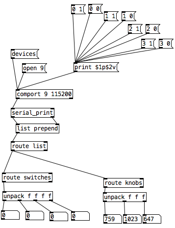
And here it is on the breadboard:
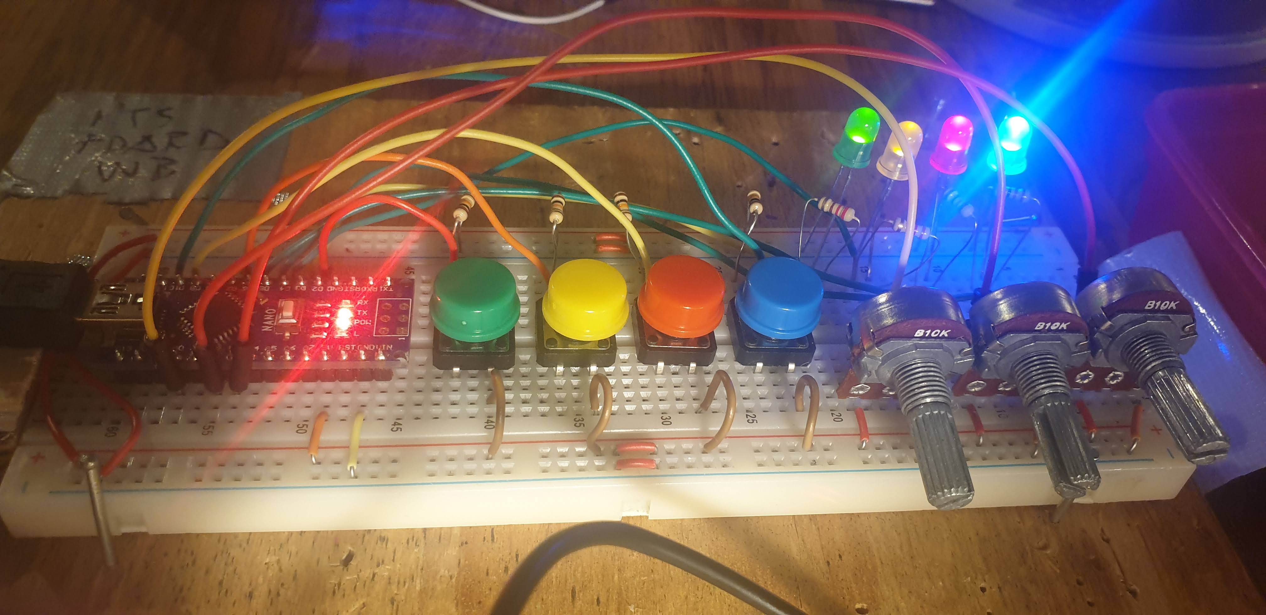
posted in I/O hardware diy
Having lots of switches into Pd
I would suggest to not mix the analog values with the digital ones. The first code could be changed to the following (using Serial.print() with the [serial_print] abstraction):
void setup()
{
  for(int i = 2; i < 14; i++)
  pinMode(i, INPUT);
  Serial.begin(115200); // perhaps use a faster baud rate
}

void loop()
{
  Serial.print("knobs"); // use "knobs" as a keyword so you can receive
  // the knob values as a list with a [r knobs] in Pd
  for(int i = 0; i < 6; i++){
    unsigned int knob = analogRead (i);
    Serial.print(" "); // first print a white space to separate the "knob" keyword from the values
    // and the values from each other
    Serial.print(knob); // then  print the actual knob value
  }
  Serial.println(); // finally print a newline character to denote end of data for keyword "knobs"

  // the same technique applies to the switches too
  // receive the switch values as a list with [r switches]
  Serial.print("switches");
  for(int i = 2; i < 14; i++) {
    int switchVal = digitalRead(i);
    Serial.print(" ");
    Serial.print(switchVal);
  }
  Serial.println();
}
As for writing to several outputs you need to set which output you want to write to and then the value you want to write. Here's an example that writes to several different digital outputs:
int pin = 0;
int val = 0;
// some random pins
int pins[4] = {3, 4, 5, 6];

void setup() {
  for (int i = 0; i < 4; i++) {
    pinMode(pins[i], OUTPUT);
    digitalWrite(pins[i], LOW);
  }

  Serial.begin(115200);
}

void loop() {
  if (Serial.available()) {
    static int temp;
    byte in = Serial.read();
    if (isDigit(in)) {
      temp = temp * 10 + in - '0';
    }
    else if (in == 'p') {
      pin = temp;
      temp = 0;
    }
    else if (in == 'v')  {
      val = temp;
      temp = 0;
      digitalWrite(pins[pin], val);
    }
}
With the code above you can send messages like this one print $1p$2v in Pd to the [comport] object. $1 is the number of the pin you want to light up starting from 0 and incrementing by 1 (so the first pin used which is pin 3 in the Arduino code would be 0 in the Pd patch), and $2 is the value, 0 or 1.
Note though that in the first code (and the code you posted), you're using all digital pins as inputs so there's no pin left to use as output. If you want to combine these two chunks of code you'll have to use less pins as inputs and leave some to be used as outputs.
 posted in I/O hardware diy
JASS, Just Another Synth...Sort-of, codename: Gemini (UPDATED: esp with midi fixes)
JASS, Just Another Synth...Sort-of, codename: Gemini (UPDATED TO V-1.0.1)
jass-v1.0.1( esp with midi fixes).zip
1.0.1-CHANGES:
- Fixed issues with midi routing, re the mode selector (mentioned below)
- Upgraded the midi mode "fetch" abstraction to be less granular
- Fix (for midi) so changing cc["14","15","16"] to "rnd" outputs a random wave (It has always done this for non-midi.)
- Added a midi-mode-tester.pd (connect PD's midi out to PD's midi in to use it)
- Upgrade: cc-56 and cc-58 can now change pbend-cc and mod-cc in all modes
- Update: the (this) readme
INFO: Values setting to 0 on initial cc changes is (given midi) to be expected.
JASS is a clone-based, three wavetable, 16 voice polyphonic, Dual-channel synth.
With...
- The initial, two wavetables combined in 1 of 5 possible ways per channel and then adding those two channels. Example: additive+frequency modulation, phase+pulse-modulation, pulse-modulation+amplitude modulation, fm+fm, etc
- The third wavetable is a ring modulator, embedded inside each mod type
- 8 wave types, including a random with a settable number of partials and a square with a settable dutycycle
- A vcf~ filter embedded inside each modulation type
- The attack-decay-release, cutoff, and resonance ranges settable so they immediately and globally recalculate all relevant values
- Four parameters /mod type: p1,p2, cutoff, and resonance
- State-saving, at both the global level (wavetables, env, etc.), as well as, multiple "substates" of for-each-mod-type settings.
- Distortion, reverb
- Midiin, paying special attention to the use of 8-knob, usb, midi controllers (see below for details)
- zexy-limiters, for each channel, after the distortion, and just before dac~
Instructions
Requires: zexy
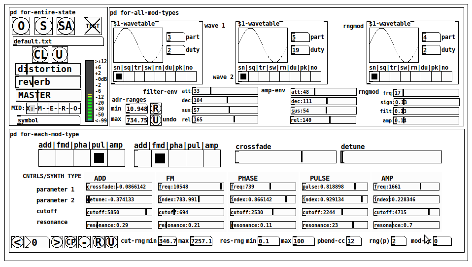
for-entire-state
- O: Open preset. "default.txt" is loaded by...default
- S: Save preset (all values incl. the multiple substates) (Note: I have Not included any presets, besides the default with 5 substates.)
- SA: Save as
- TEST: A sample player
- symbol: The filename of the currently loaded preset
- CL: Clear, sets all but a few values to 0
- U: Undo CL
- distortion,reverb,MASTER: operate on the total out, just before the limiter.
- MIDI (Each selection corresponds to a pgmin, 123,124,125,126,127, respectively, see below for more information)
- X: Default midi config, cc[1,7,8-64] available
- M: Modulators;cc[10-17] routed to ch1&ch2: p1,p2,cutoff,q controls
- E: Envelopes; cc[10-17] routed to filter- and amp-env controls
- R: Ranges; cc[10-17] routed to adr-min/max,cut-off min/max, resonance min/max, distortion, and reverb
- O: Other; cc[10-17] routed to rngmod controls, 3 wavetypes, and crossfade
- symbol: you may enter 8 cc#'s here to replace the default [10-17] from above to suit your midi-controller's knob configuration; these settings are saved to file upon entry
- vu: for total out to dac~
for-all-mod-types
- /wavetable
- graph: of the chosen wavetype
- part: partials, # of partials to use for the "rn" wavetype; the resulting, random sinesum is saved with the preset
- duty: dutycycle for the "du" wavetype
- type: sin | square | triangle | saw | random | duty | pink (pink-noise: a random sinesum with 128 partials, it is not saved with the preset) | noise (a random sinesum with 2051 partials, also not saved)
- filter-env: (self-explanatory)
- amp-env: (self-explanatory)
- rngmod: self-explanatory, except "sign" is to the modulated signal just before going into the vcf~
- adr-range: min,max[0-10000]; changing these values immediately recalculates all values for the filter- and amp-env's scaled to the new range
- R: randomizes all for-all-mod-types values, but excludes wavetype "noise"; rem: you must S or SA the preset to save the results
- U: Undoes R
for-each-mod-type
- mod-type-1: (In all cases, wavetable1 is the carrier and wavetable2 is the modulator); additive | frequency | phase | pulse | amplitude modulation
- mod-type-2: Same as above; mod-type-2 May be the same type as mod-type-1
- crossfade: Between ch1 and ch2
- detune: Applied to the midi pitch going into ch2
- for-each-clone-type controls:
- p1,p2: (self-explanatory)
- cutoff, resonance: (self-explanatory)
- navigation: Cycles through the saved substates of for-each-mod-type settings (note: they are lines on the end of a [text])
- CP: Copy the current settings, ie. add a line to the end of the [text] identical to the current substate
- -: Delete the current substate
- R: Randomize all (but only a few) substate settings
- U: Undo R
- cut-rng: min,max[0-20000] As adr-range above, this immediately recalculates all cutoff values
- res-rng: min,max[0-100], same as previously but for q
- pbend: cc,rng: the pitchwheel may be assigned to a control by setting this to a value >7 (see midi table below for possibilities); rng is in midi pitches (+/- the value you enter)
- mod-cc: the mod-wheel may be assigned to a control [7..64] by setting this value
midi-implementation
| name | --- | Description |
|---|---|---|
| sysex | not supported | |
| pgmin | 123,124,125,126,127; They set midi mode | |
| notein | 0-127 | |
| bendin | pbend-cc=7>pitchbend; otherwise to the cc# from below | |
| touch | not supported | |
| polytouch | not supported |
cc - basic (for all midi-configs)
| # | name | --- | desciption |
|---|---|---|---|
| 1 | mod-wheel | (assignable) | |
| 7 | volume | Master |
cc - "X" mode/pgmin=123
| cc | --- | parameter |
|---|---|---|
| 8 | wavetype1 | |
| 9 | partials 1 | |
| 10 | duty 1 | |
| 11 | wavetype2 | |
| 12 | partials 2 | |
| 13 | duty 2 | |
| 14 | wavetype3 | |
| 15 | partials 3 | |
| 16 | duty 3 | |
| 17 | filter-att | |
| 18 | filter-dec | |
| 19 | filter-sus | |
| 20 | filter-rel | |
| 21 | amp-att | |
| 22 | amp-dec | |
| 23 | amp-sus | |
| 24 | amp-rel | |
| 25 | rngmod-freq | |
| 26 | rngmod-sig | |
| 27 | rngmod-filt | |
| 28 | rngmod-amp | |
| 29 | distortion | |
| 30 | reverb | |
| 31 | master | |
| 32 | mod-type 1 | |
| 33 | mod-type 2 | |
| 34 | crossfade | |
| 35 | detune | |
| 36 | p1-1 | |
| 37 | p2-1 | |
| 38 | cutoff-1 | |
| 39 | q-1 | |
| 40 | p1-2 | |
| 41 | p2-2 | |
| 42 | cutoff-2 | |
| 43 | q-2 | |
| 44 | p1-3 | |
| 45 | p2-3 | |
| 46 | cutoff-3 | |
| 47 | q-3 | |
| 48 | p1-4 | |
| 49 | p2-4 | |
| 50 | cutoff-4 | |
| 51 | q-4 | |
| 52 | p1-5 | |
| 53 | p2-5 | |
| 54 | cutoff-5 | |
| 55 | q-5 | |
| 56 | pbend-cc | |
| 57 | pbend-rng | |
| 58 | mod-cc | |
| 59 | adr-rng-min | |
| 60 | adr-rng-max | |
| 61 | cut-rng-min | |
| 62 | cut-rng-max | |
| 63 | res-rng-min | |
| 64 | res-rng-max |
cc - Modes M, E, R, O
Jass is designed so that single knobs may be used for multiple purposes without reentering the previous value when you turn the knob, esp. as it pertains to, 8-knob controllers.
Thus, for instance, when in Mode M(pgm=124) your cc send the signals as listed below. When you switch modes, that knob will then change the values for That mode.
In order to do this, you must turn the knob until it hits the previously stored value for that mode-knob.
After hitting that previous value, it will begin to change the current value.
cc - Modes M, E, R, O assignments
Where [10..17] may be the midi cc #'s you enter in the MIDI symbol field (as mentioned above) aligned to your particular midi controller.
| cc# | --- | M/pgm=124 | --- | E/pgm=125 | --- | R/pgm=126 | --- | O/pgm=127 |
|---|---|---|---|---|---|---|---|---|
| 10 | ch1:p1 | filter-env:att | adr-rng-min | rngmod:freq | ||||
| 11 | ch1:p2 | filter-env:dec | adr-rng-max | rngmod:sig | ||||
| 12 | ch1:cutoff | filter-env:sus | cut-rng-min | rngmod:filter | ||||
| 13 | ch1:q | filter-env:re | cut-rng-max | rngmod:amp | ||||
| 14 | ch2:p1 | amp-env:att | res-rng-min | wavetype1 | ||||
| 15 | ch2:p2 | amp-env:dec | res-rng-max | wavetype2 | ||||
| 16 | ch2:cutoff | amp-env:sus | distortion | wavetype3 | ||||
| 17 | ch2:q | amp-env:rel | reverb | crossfade |
In closing
If you have anywhere close to as much fun (using, experimenting with, trying out, etc.) this patch, as I had making it, I will consider it a success.
For while an arduous learning curve (the first synth I ever built), it has been an Enormous pleasure to listen to as I worked on it. Getting better and better sounding at each pass.
Rather, than say to much, I will say this:
Enjoy. May it bring a smile to your face.
Peace through love of creating and sharing.
Sincerely,
Scott
 posted in patch~