Having lots of switches into Pd
@alexandros thanks, it all works!
I merged the codes for in and outs and also changed so you can set up all of the pins with arrays (as you did in the latter code). Then you can set up the pins in any order.
Here is the Arduino code. Do you spot any errors I may have introduced?
//number of elements in array need to match for() cycles
int pinsIn[4] = {2, 7, 10, 11};
int pinsAnalog[3] = {0, 2, 3};

int pin = 0;
int val = 0;
// some random pins
int pinsOut[4] = {3, 4, 5, 6};

void setup()
{
  //set up a total of pins for input (has to match number of elements in array)
  for(int i = 0; i < 4; i++)
  pinMode(pinsIn[i], INPUT);

  for (int i = 0; i < 4; i++) {
    pinMode(pinsOut[i], OUTPUT);
    digitalWrite(pinsOut[i], LOW);
  }

  Serial.begin(115200); // perhaps use a faster baud rate
}

void loop()
{
  Serial.print("knobs"); // use "knobs" as a keyword so you can receive
  // the knob values as a list with a [r knobs] in Pd
  for(int i = 0; i < 3; i++){
    unsigned int knob = analogRead (pinsAnalog[i]);
    Serial.print(" "); // first print a white space to separate the "knob" keyword from the values
    // and the values from each other
    Serial.print(knob); // then  print the actual knob value
  }
  Serial.println(); // finally print a newline character to denote end of data for keyword "knobs"

  // the same technique applies to the switches too
  // receive the switch values as a list with [r switches]
  Serial.print("switches");
  for(int i = 0; i < 4; i++) {
    int switchVal = digitalRead(pinsIn[i]);
    Serial.print(" ");
    Serial.print(switchVal);
  }
  Serial.println();

  //handle digital outputs
  if (Serial.available()) {
    static int temp;
    byte in = Serial.read();
    if (isDigit(in)) {
      temp = temp * 10 + in - '0';
    }
    else if (in == 'p') {
      pin = temp;
      temp = 0;
    }
    else if (in == 'v')  {
      val = temp;
      temp = 0;
      digitalWrite(pinsOut[pin], val);
    }
}
}
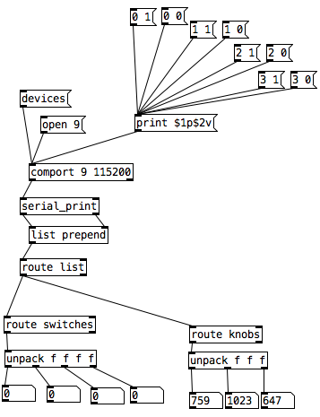
In Pd I was not able to use [r switches] or [r knobs] but had to use [route]. Is this the correct way to use [serial_print]?
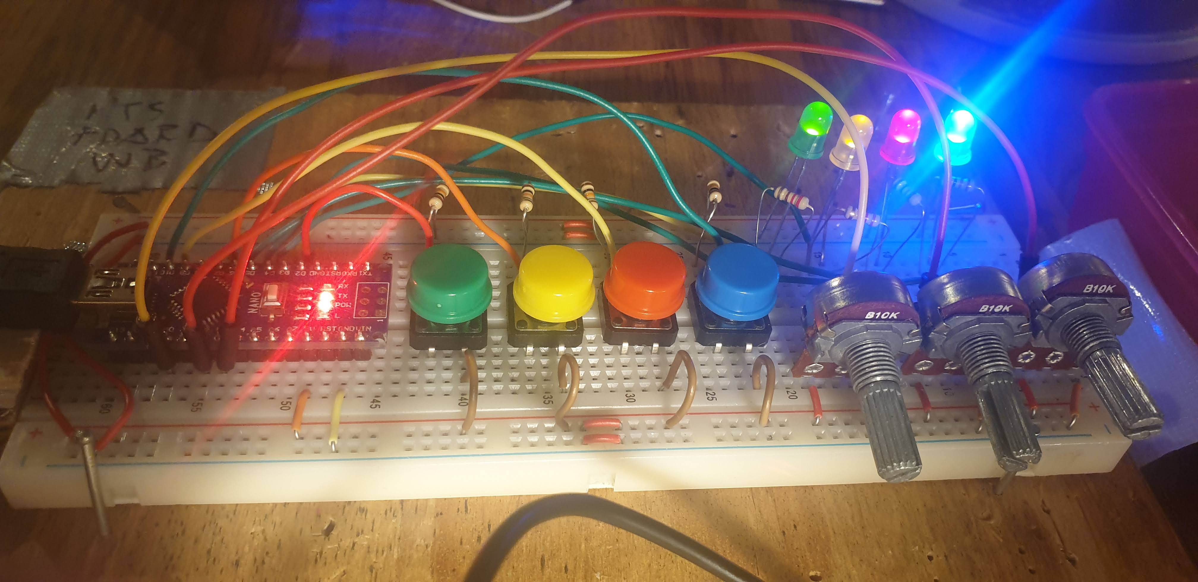
And here it is on the breadboard:
 posted in I/O hardware diy
Having lots of switches into Pd
I would suggest to not mix the analog values with the digital ones. The first code could be changed to the following (using Serial.print() with the [serial_print] abstraction):
void setup()
{
  for(int i = 2; i < 14; i++)
  pinMode(i, INPUT);
  Serial.begin(115200); // perhaps use a faster baud rate
}

void loop()
{
  Serial.print("knobs"); // use "knobs" as a keyword so you can receive
  // the knob values as a list with a [r knobs] in Pd
  for(int i = 0; i < 6; i++){
    unsigned int knob = analogRead (i);
    Serial.print(" "); // first print a white space to separate the "knob" keyword from the values
    // and the values from each other
    Serial.print(knob); // then  print the actual knob value
  }
  Serial.println(); // finally print a newline character to denote end of data for keyword "knobs"

  // the same technique applies to the switches too
  // receive the switch values as a list with [r switches]
  Serial.print("switches");
  for(int i = 2; i < 14; i++) {
    int switchVal = digitalRead(i);
    Serial.print(" ");
    Serial.print(switchVal);
  }
  Serial.println();
}
As for writing to several outputs you need to set which output you want to write to and then the value you want to write. Here's an example that writes to several different digital outputs:
int pin = 0;
int val = 0;
// some random pins
int pins[4] = {3, 4, 5, 6];

void setup() {
  for (int i = 0; i < 4; i++) {
    pinMode(pins[i], OUTPUT);
    digitalWrite(pins[i], LOW);
  }

  Serial.begin(115200);
}

void loop() {
  if (Serial.available()) {
    static int temp;
    byte in = Serial.read();
    if (isDigit(in)) {
      temp = temp * 10 + in - '0';
    }
    else if (in == 'p') {
      pin = temp;
      temp = 0;
    }
    else if (in == 'v')  {
      val = temp;
      temp = 0;
      digitalWrite(pins[pin], val);
    }
}
With the code above you can send messages like this one print $1p$2v in Pd to the [comport] object. $1 is the number of the pin you want to light up starting from 0 and incrementing by 1 (so the first pin used which is pin 3 in the Arduino code would be 0 in the Pd patch), and $2 is the value, 0 or 1.
Note though that in the first code (and the code you posted), you're using all digital pins as inputs so there's no pin left to use as output. If you want to combine these two chunks of code you'll have to use less pins as inputs and leave some to be used as outputs.
 posted in I/O hardware diy
JASS, Just Another Synth...Sort-of, codename: Gemini (UPDATED: esp with midi fixes)
JASS, Just Another Synth...Sort-of, codename: Gemini (UPDATED TO V-1.0.1)
jass-v1.0.1( esp with midi fixes).zip
1.0.1-CHANGES:
- Fixed issues with midi routing, re the mode selector (mentioned below)
- Upgraded the midi mode "fetch" abstraction to be less granular
- Fix (for midi) so changing cc["14","15","16"] to "rnd" outputs a random wave (It has always done this for non-midi.)
- Added a midi-mode-tester.pd (connect PD's midi out to PD's midi in to use it)
- Upgrade: cc-56 and cc-58 can now change pbend-cc and mod-cc in all modes
- Update: the (this) readme
INFO: Values setting to 0 on initial cc changes is (given midi) to be expected.
JASS is a clone-based, three wavetable, 16 voice polyphonic, Dual-channel synth.
With...
- The initial, two wavetables combined in 1 of 5 possible ways per channel and then adding those two channels. Example: additive+frequency modulation, phase+pulse-modulation, pulse-modulation+amplitude modulation, fm+fm, etc
- The third wavetable is a ring modulator, embedded inside each mod type
- 8 wave types, including a random with a settable number of partials and a square with a settable dutycycle
- A vcf~ filter embedded inside each modulation type
- The attack-decay-release, cutoff, and resonance ranges settable so they immediately and globally recalculate all relevant values
- Four parameters /mod type: p1,p2, cutoff, and resonance
- State-saving, at both the global level (wavetables, env, etc.), as well as, multiple "substates" of for-each-mod-type settings.
- Distortion, reverb
- Midiin, paying special attention to the use of 8-knob, usb, midi controllers (see below for details)
- zexy-limiters, for each channel, after the distortion, and just before dac~
Instructions
Requires: zexy
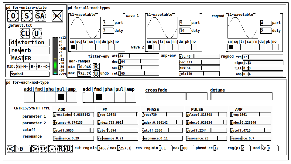
for-entire-state
- O: Open preset. "default.txt" is loaded by...default
- S: Save preset (all values incl. the multiple substates) (Note: I have Not included any presets, besides the default with 5 substates.)
- SA: Save as
- TEST: A sample player
- symbol: The filename of the currently loaded preset
- CL: Clear, sets all but a few values to 0
- U: Undo CL
- distortion,reverb,MASTER: operate on the total out, just before the limiter.
- MIDI (Each selection corresponds to a pgmin, 123,124,125,126,127, respectively, see below for more information)
- X: Default midi config, cc[1,7,8-64] available
- M: Modulators;cc[10-17] routed to ch1&ch2: p1,p2,cutoff,q controls
- E: Envelopes; cc[10-17] routed to filter- and amp-env controls
- R: Ranges; cc[10-17] routed to adr-min/max,cut-off min/max, resonance min/max, distortion, and reverb
- O: Other; cc[10-17] routed to rngmod controls, 3 wavetypes, and crossfade
- symbol: you may enter 8 cc#'s here to replace the default [10-17] from above to suit your midi-controller's knob configuration; these settings are saved to file upon entry
- vu: for total out to dac~
for-all-mod-types
- /wavetable
- graph: of the chosen wavetype
- part: partials, # of partials to use for the "rn" wavetype; the resulting, random sinesum is saved with the preset
- duty: dutycycle for the "du" wavetype
- type: sin | square | triangle | saw | random | duty | pink (pink-noise: a random sinesum with 128 partials, it is not saved with the preset) | noise (a random sinesum with 2051 partials, also not saved)
- filter-env: (self-explanatory)
- amp-env: (self-explanatory)
- rngmod: self-explanatory, except "sign" is to the modulated signal just before going into the vcf~
- adr-range: min,max[0-10000]; changing these values immediately recalculates all values for the filter- and amp-env's scaled to the new range
- R: randomizes all for-all-mod-types values, but excludes wavetype "noise"; rem: you must S or SA the preset to save the results
- U: Undoes R
for-each-mod-type
- mod-type-1: (In all cases, wavetable1 is the carrier and wavetable2 is the modulator); additive | frequency | phase | pulse | amplitude modulation
- mod-type-2: Same as above; mod-type-2 May be the same type as mod-type-1
- crossfade: Between ch1 and ch2
- detune: Applied to the midi pitch going into ch2
- for-each-clone-type controls:
- p1,p2: (self-explanatory)
- cutoff, resonance: (self-explanatory)
- navigation: Cycles through the saved substates of for-each-mod-type settings (note: they are lines on the end of a [text])
- CP: Copy the current settings, ie. add a line to the end of the [text] identical to the current substate
- -: Delete the current substate
- R: Randomize all (but only a few) substate settings
- U: Undo R
- cut-rng: min,max[0-20000] As adr-range above, this immediately recalculates all cutoff values
- res-rng: min,max[0-100], same as previously but for q
- pbend: cc,rng: the pitchwheel may be assigned to a control by setting this to a value >7 (see midi table below for possibilities); rng is in midi pitches (+/- the value you enter)
- mod-cc: the mod-wheel may be assigned to a control [7..64] by setting this value
midi-implementation
| name | --- | Description |
|---|---|---|
| sysex | not supported | |
| pgmin | 123,124,125,126,127; They set midi mode | |
| notein | 0-127 | |
| bendin | pbend-cc=7>pitchbend; otherwise to the cc# from below | |
| touch | not supported | |
| polytouch | not supported |
cc - basic (for all midi-configs)
| # | name | --- | desciption |
|---|---|---|---|
| 1 | mod-wheel | (assignable) | |
| 7 | volume | Master |
cc - "X" mode/pgmin=123
| cc | --- | parameter |
|---|---|---|
| 8 | wavetype1 | |
| 9 | partials 1 | |
| 10 | duty 1 | |
| 11 | wavetype2 | |
| 12 | partials 2 | |
| 13 | duty 2 | |
| 14 | wavetype3 | |
| 15 | partials 3 | |
| 16 | duty 3 | |
| 17 | filter-att | |
| 18 | filter-dec | |
| 19 | filter-sus | |
| 20 | filter-rel | |
| 21 | amp-att | |
| 22 | amp-dec | |
| 23 | amp-sus | |
| 24 | amp-rel | |
| 25 | rngmod-freq | |
| 26 | rngmod-sig | |
| 27 | rngmod-filt | |
| 28 | rngmod-amp | |
| 29 | distortion | |
| 30 | reverb | |
| 31 | master | |
| 32 | mod-type 1 | |
| 33 | mod-type 2 | |
| 34 | crossfade | |
| 35 | detune | |
| 36 | p1-1 | |
| 37 | p2-1 | |
| 38 | cutoff-1 | |
| 39 | q-1 | |
| 40 | p1-2 | |
| 41 | p2-2 | |
| 42 | cutoff-2 | |
| 43 | q-2 | |
| 44 | p1-3 | |
| 45 | p2-3 | |
| 46 | cutoff-3 | |
| 47 | q-3 | |
| 48 | p1-4 | |
| 49 | p2-4 | |
| 50 | cutoff-4 | |
| 51 | q-4 | |
| 52 | p1-5 | |
| 53 | p2-5 | |
| 54 | cutoff-5 | |
| 55 | q-5 | |
| 56 | pbend-cc | |
| 57 | pbend-rng | |
| 58 | mod-cc | |
| 59 | adr-rng-min | |
| 60 | adr-rng-max | |
| 61 | cut-rng-min | |
| 62 | cut-rng-max | |
| 63 | res-rng-min | |
| 64 | res-rng-max |
cc - Modes M, E, R, O
Jass is designed so that single knobs may be used for multiple purposes without reentering the previous value when you turn the knob, esp. as it pertains to, 8-knob controllers.
Thus, for instance, when in Mode M(pgm=124) your cc send the signals as listed below. When you switch modes, that knob will then change the values for That mode.
In order to do this, you must turn the knob until it hits the previously stored value for that mode-knob.
After hitting that previous value, it will begin to change the current value.
cc - Modes M, E, R, O assignments
Where [10..17] may be the midi cc #'s you enter in the MIDI symbol field (as mentioned above) aligned to your particular midi controller.
| cc# | --- | M/pgm=124 | --- | E/pgm=125 | --- | R/pgm=126 | --- | O/pgm=127 |
|---|---|---|---|---|---|---|---|---|
| 10 | ch1:p1 | filter-env:att | adr-rng-min | rngmod:freq | ||||
| 11 | ch1:p2 | filter-env:dec | adr-rng-max | rngmod:sig | ||||
| 12 | ch1:cutoff | filter-env:sus | cut-rng-min | rngmod:filter | ||||
| 13 | ch1:q | filter-env:re | cut-rng-max | rngmod:amp | ||||
| 14 | ch2:p1 | amp-env:att | res-rng-min | wavetype1 | ||||
| 15 | ch2:p2 | amp-env:dec | res-rng-max | wavetype2 | ||||
| 16 | ch2:cutoff | amp-env:sus | distortion | wavetype3 | ||||
| 17 | ch2:q | amp-env:rel | reverb | crossfade |
In closing
If you have anywhere close to as much fun (using, experimenting with, trying out, etc.) this patch, as I had making it, I will consider it a success.
For while an arduous learning curve (the first synth I ever built), it has been an Enormous pleasure to listen to as I worked on it. Getting better and better sounding at each pass.
Rather, than say to much, I will say this:
Enjoy. May it bring a smile to your face.
Peace through love of creating and sharing.
Sincerely,
Scott
 posted in patch~
abs-fetch-slider: using a value (slider) multiple ways based on creation argument
abs-fetch-slider: using a value (slider) multiple ways based on creation argument
abs-fetch-slider-help.pd
abs-fetch-slider.pd
;
reuse a value by only changing the value;
once the value matches the previously set value;
for that index/creation argumet.;
;
USECASE:;
Getting a (hardware) knob to serve multiple functions;
by only having it change its value once the previous value for that index is hit.;
(See the help file for details, using two ctlin to set multiple values)
;
Background:;
I have found it very frustrating that when using hardware you can't use one knob for multiple purposes because the knob is literally always in the last state you left it.;
;
one creation argument: the identifying index;
two inlets: left: the incoming value and right the index;
one outlet the value for that index
So...
When you change the index, just change the knob until the audio, image, value, etc., i.e. result starts changing.
It will ONLY change once the previously set value for that index is hit..
So it "saves state".
Peace.
Stay Safe.
-S
posted in abstract~
can't find [knob]
@raynovich Uliss CEAMMC has a 64-bit gui knob [ui.knob]
It is available for 64 bit Pd in windows and probably for other os's through Deken.
If you need to compile it then I think this is the correct link.....
https://github.com/uliss/pure-data/tree/ceammc/ceammc/distrib
For Linux there is an OS specific distribution for many systems through Snap.....
https://snapcraft.io/pd-ceammc
David.
P.S. All of Millers Pd downloads.... 0.49 0.50 0.51........ and before..... and after...... are "Vanilla" as they have no extra externals bundled into the download.
.......... Externals can be added through "Deken" like this........
You can install externals easily for your system by opening help from the top menu in Pd.
Then click "Find Externals" and in the search box type (for example)........ knob
All libraries that are available for your version of Pd that have an object with knob in its name will appear.
Select the library you want and follow the instructions and restart Pd when it is done.
 posted in technical issues
can't find [knob]
couldn't think how else to word it
I'm told that [knob] is in iemlib so i've installed it through synaptic package manager and everything in there (apart from [knob]) seems to be working fine. The problem is... that knob.pd isn't actually in the folder. Neither is it's help files or anything. I was then told that [mknob] in moonlib is a good alternative... so i installed that and this time the mknob-help.pd file is there and there is an mknob.pd_linux but there is no mknob.pd so not working either
All other externals in both libraries are working fine so it seems like they are installed correctly. but then im using synaptic so why wouldn't they be. The preoblem seems to be that the actual files are missing from the downloaded folders.
any ideas on how to fix? Perhaps if i could just get a copy of mknob.pd or knob.pd and stick it in my extras folder
 posted in technical issues
scalar knob
a scalar knob for pd with following features:
- value inlet and outlet
- set parameters on the fly:
- size
- color theme
- mouse sensitivity
- background visisbility
- value range (min, max, exponent for nonlinear course of values)
- reset value
- reset on doubleclick
- save state with patch (via connected numberbox2)
here's a simple example how to use with default settings:

and here the zip file:
t_knob.zip
this knob abstraction is based on a patch, i found here in the forum - for some reason i can't find the thread anymore.... i believe it was a patch by @Balwyn, but not 100% sure - could you confirm?
in this knob abstraction, i use a numberbox2 instead of a slider, which is not part of the abstraction itself for two reasons: the numberbox2 can be used to save the state of the knob and reinitialize by loadbang and it avoids graphical issues, if it's not incorporated within the abstraction. the numberbox2 receives parameter adjustments by the abstraction (like size, range (for mouse response), and init option). you can set the color theme, the output range (with exponent for nonlinear values), a reset value (to reset on doubleclick), the size and the mouse response. have a look at the help patch included in the zip file for further informations.
 posted in abstract~
Stomp-board my current project
@Jona I've started looking at ofelia and came up with this for a knob radial-knob.zip but that was long after I started stompboard. I have a lite version of stompboard using canvases and vslider for the knobs but it has some (a lot of) errors popping up and looks a bit odd Pd-effects - lite.zip
and here is link to some recordings using the grater effect
 posted in patch~
MobMuPlat OSC-to-MIDI Remote Control, spec. for PD, Guitarix, and Rakarrack and other guitar effects apps
It's always funny to me how working on one PD project results in fruit that might also prove useful.
Currently, working on a broader project, but this part (at least) (I think) is ready for distribution.
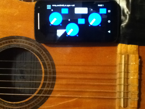
Background: I Really hate leaving the side of my guitar (for example to click a mouse or tweak a setting) when I am playing. So designed this mmp app so that I can attach (with funtack, ex.) my handheld to my guitar and control my settings from there or perhaps even as I play. Like so:
[Aside: the broader project also includes (on the front-side of the app) controls driven by the handheld's tilt, as well as, the adc~ pitch, env~, and distance of the pitch from a "center". But that part has to wait (though the code is all inside the mmp_osc2midi_rc.pd patch just disconnected/does not use the cpu).]
SETUP (linux is what I know, so other OSes may work just can't/haven't tested them):
JACK
Pure Data
a2jmidid - JACK MIDI daemon for ALSA MIDI (in the Ubuntu at least repos)
guitarix a/o rakarrack, or other midi-driven effects apps (such as the included set of 30 pd effects(see below))
PIECES:
The mmp_osc2midi_rc.zip (extract(android)/install(ios) to MobMuPlat directory)
The osc2midi_bridge.zip (to be run on the "pd receiver") and includes the osc2midi_bridge.pd, help file, and a set of 30 mmp-ready-(mono) effects (in the ./effs directory) that can be used if PD is to be used as the receiver. (They are standardized to include 3 inlets: left=inlet~, center=[0 $1(, [1 $1(, [2 $1( messages sent to 3 parameters on the effect, and right=[switch~] and 1 outlet~ and a demo guitarix "bank" file called "MIDITEST.gx" (which includes 2 presets/programs and set midi values (0-8) to test. Just add the file to the guitarix config "banks" folder).
Instructions:
- Start Jack;
- In Pure Data, open the osc2midi_bridge-help.pd file; toggle "listen" on; and set MEDIA to "ALSA-MIDI" (the additional pieces are just examples of receiving the midi values);
- In Jack>ALSA: Connect Read:MIDI to Write:PD & Read:PD to Write:Midi;
- From the command line execute "a2j_control start" (no quotes);
- Start (ex.) guitarix;
- In Jack>Midi connect a2j:Pure Data(capture) to (ex) gx_head_amp:midi_in_1.
Note/Alert/etc. For a machine to receive OSC messages the recipient-computer's firewall must (I believe) be turned off.
GUI:
The GUI has 3 pages that look (basically) as follows (with the subsequent 2 pages having only the 3 knobs and 3 buttons).
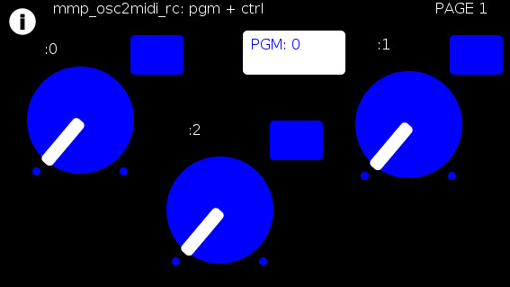
The buttons trigger text entry boxes which allow you to enter numbers (0-127) representing:
PGM: the number sent to (midi) [pgm]
and
(the buttons beside the knobs) the midi value, i.e [ctrl] (0-127), each knob is to be sent to (all on channel=0). (The resulting number of which are all written to the label to the left.)
For example:
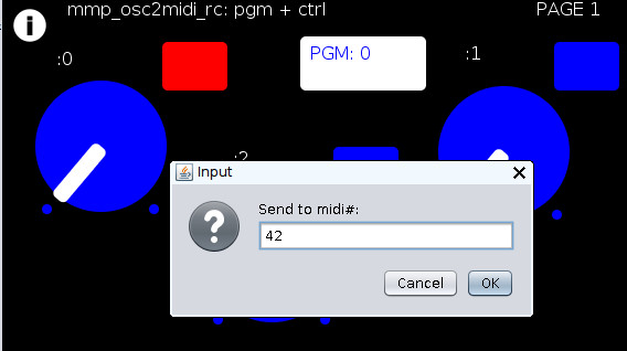
Results in:
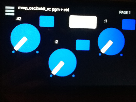
You can now to do 1 of 2 things:
Set the mmp-knobs to whatever midi values you have set in guitarix
or
Set the guitarix midi values (mousewheel click on a control) to one of the mmp preset 0-8 midi values.
WOW!!!
That took a helluva a lot of writing (and reading) but I hope you can both see the value and make use of this bit of technology.
As I said before,
I look forward to being able to fine tune my sound ALL while my hands and I are BOTH still at my guitar and not bend over, move, etc. etc. etc. to get the sound I want.
Peace, Love, and Ever-Lasting Good Cheer.
If you made it this far ") , Thanks for Listening.
, Thanks for Listening.
Sincerely and Optimistically,
Scott
p.s. ask whatever you want regarding setup, how to use, points-of-clarification, etc. I am more than happy to help.
"Out of Love comes Joy"
posted in patch~
About a simple MIDI monosynth patch on Pd_intro.pdf
@Leorange If you want to test the whole patch (including [notein] you will need some external software to produce midi messages, and also to "loop" them "back" within your system (OS dependant for the software).
That is because [notein] receives midi messages directly from your OS..... so you cannot "fake" it.
But...... if you right-click [stripnote].... then help...... you will see that it receives messages from [notein].
So you can send "fake" messages to [stripnote] to make your patch work.
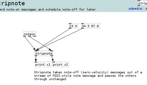
When you send a "list" to the left inlet of an object the contents of the list are distributed across the inlets of the object.
So in the pic above, if you click the message [34.5 67.8( then "67.8" goes first to the right inlet of [stripnote] and then "34.5" goes immediately to the left inlet, which, because the left inlet is "hot", "bangs" [stripnote] and makes it do its stuff.
All objects operate "right to left" which means that [notein] sends from its right outlet first, then middle, then left.
So your message is simulating the output from [notein]
This is a good read........ http://puredata.info/docs/manuals/pd/x2.htm
David.
posted in technical issues