Smooth frequency transition
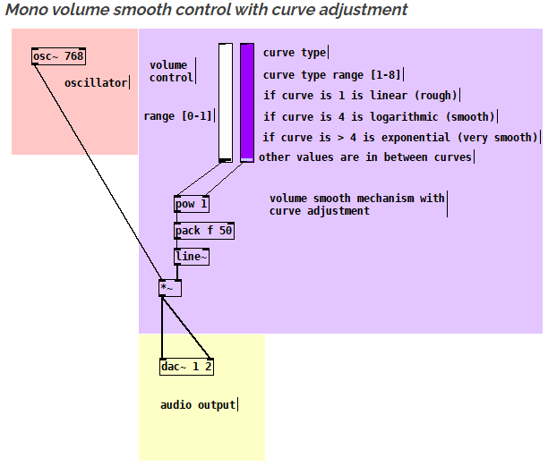
you should use a logarithmic line~ object to adjust the curve as smooth as you want.
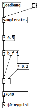
On top of that you should apply a Nyquist correction to the output of your oscillator abstraction.
So here you have some imagines how to do that. The Nyquist abstraction is used in the output of the triangle oscillator abstraction as an example. Then the final output can be controlled with a logarithmic line~ object.
OBS : If you need more then one oscillator you can apply this for each oscillator and then use a mixer and then the output of the mixer you use again the same idea. In this way you have an oscillator smooth stage control and a final mixer stage control for extra smoothness.
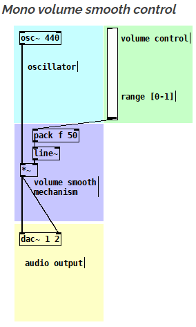
This is just the simple mono smooth control (no curve adjustment)
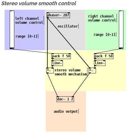
The same idea but as a stereo version
Here is with logarithmic smooth control (with curve adjustment)
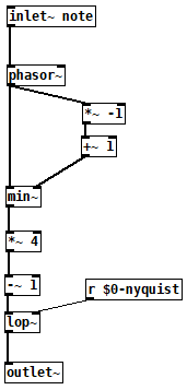
Here you have a Nyquist correction abstraction
Here you have a triangle oscillator with Nyquist correction
You can also download xline~ which is an object that is doing just that :
https://forum.pdpatchrepo.info/topic/13084/xline-logarithmic-line-object
 posted in technical issues
On the off chance this might save you some trouble
How to connect multiple outlets to multiple inlets, etc.
(I saw someone do this on a video so looked it up.
The info was originally posted on the newsgroup at:
[link Intelligent Patching](link https://lists.puredata.info/pipermail/pd-list/2018-06/122789.html) by IOhannes m zmoelnig .)
These do work. Just sort of tricky to get the steps right.
quote:
Intelligent Patching
new connection features:
-
select any two objects, and press <Ctrl>+<k> (or <Cmd>+<k> if you insist), to connect them (trivially, so just the first inlet)
-
to connect a (signal) outlet to multiple arbitrary inlets, you can now press <Shift> while hovering the yet-unconnected cord over an inlet
-
to add more connections between two already connected object, select the connection and pressl <Ctrl>+<d> to extend the connections to the right ("duplicate")
-
to fully connect two objects, select both objects before connecting them.
-
to connect multiple objects to a single inlet, select all the source objects (but not the sink object) before connecting them.
-
(the other way round works as well, but will give you fan-outs!!!)
-
to connect multiple objects to a multi-inlet object, select all the source objects and the sink object before connecting the leftmost source to the leftmost inlet.
-
to connect a multi-outlet object to multiple objects, select all the source object and all the sink objects before connecting the leftmost outlet to the leftmost sink.
:end quote
May the info/techniques help to expedite yr work flow.
Peace through sharing.
-S
 posted in tutorials
Windowed-sync oscillator: Style questions
@jameslo "Since many programmers seem to want to avoid [fexpr~] at all costs, maybe you could rewrite your [fexpr~] with [expr~ $v1 > $v2] and [rzero_rev~ 0]"
Hmm, yeah. I had thought that both [expr~] and [fexpr~] were said to be bad for performance.
I suppose this might be another way to do a signal-rate comparison:
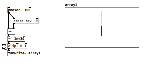
There's a very small chance of the [-~] result being between 0 and 1e-30, where the clip~ value would be between zero and one but not exactly either. With typical signal magnitudes, that's unlikely, so this wouldn't work in cases where only 0 and 1 are acceptable.
+1 RE the mystifying omissions and irregularities in vanilla. Since I started thinking of it as a scripting language (and stopped comparing it to c, c++, c#, Java...) everything became happy and easy-going.
Yes and no... Pd is an important and valuable tool and it's good to make friends with it as it is. At the same time, lack of some core operators can be seen as a usability issue.
I definitely wouldn't compare it to C and such. Miller Puckette himself acknowledges[1] that many algorithms are straightforward to write in procedural languages (and maybe even more straightforward in functional languages), but rip-your-hair-out painful in dataflow patchers. E.g., quicksort, which in Haskell goes:
quicksort :: Ord a => [a] -> [a]
quicksort []     = []
quicksort (p:xs) = (quicksort lesser) ++ [p] ++ (quicksort greater)
    where
        lesser  = filter (< p) xs
        greater = filter (>= p) xs
and in C is... somewhat longer but still a fairly straightforward recursive implementation.
I can literally not even imagine how to implement a quicksort in Pd.
In SuperCollider, I'm doing most of my performances using a sequence-scripting language of my own design, where SC code is parsing the expressions and translating them into SC patterns. That's been a long project but within reach of an object-oriented language with a full suite of data structures. Pd... again, I can't imagine where to begin.
Puckette points out in that interview that Max and Pd are designed to react to input events, and they are very elegant for this. In Pd, you can connect a slider to a number box. In SC, the same is:
(
var number, slider;

w = Window("slider", Rect(800, 200, 500, 400)).front;
w.layout = VLayout(
    nil,
    HLayout(
        number = NumberBox().fixedWidth_(80),
        slider = Slider().orientation_(\horizontal)
    ),
    nil
);

slider.action = { |view|
    number.value = view.value;
};
)
In that case, definitely, Pd's expression of the idea of a value flowing from an interface object toward the display object is as concise as you can imagine, and SC's version is verbose and puzzling until you get used to it. Use the tool that's right for the job.
lacuna:
There are [vphasor~], [vphasor2~] and [vsamphold~] from @Maelstorm .
Oh that's good.
It's hard to find extensions like this, if you don't know where it is.
In your patch [rpole~ 1] is working with a signal-inlet, isn't it?
Yes. The idea is, while the (signal) coefficient is 1, then the left-hand signal gets integrated. If, for a single sample, both the signal and coefficient are 0, then the output is 0, and it will start integrating again as soon as the coefficient flips back to 1.
Which is that other forum you mentioned?
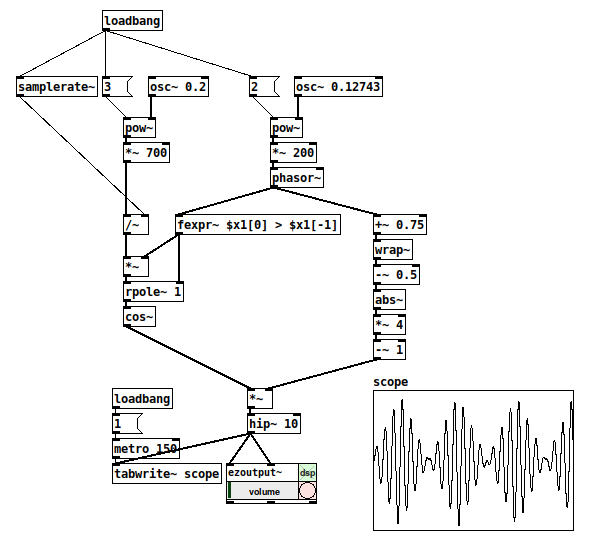
TBH I think SC wins in terms of clear expression of this synthesis algorithm:
(
{
    var sync = LFTri.ar(SinOsc.kr(0.2).exprange(100, 400));
    var phase = Sweep.ar(sync, SinOsc.kr(0.12743).exprange(700/3, 2100));
    var synced = SinOsc.ar(0, (phase % 1) * 2pi);
    dup(LeakDC.ar(synced * sync) * 0.1)
}.play;
)
This is part of what I mean by "usability issues" -- Pd: 7 objects for the triangle wave vs SC: LFTri.ar(freq), or the automatic exponential scaling exprange, and Sweep has a signal-rate retrigger built-in (there's also a range-rewrapping Phasor, and it has an audio-rate trigger too)... SC's initial learning curve is steeper but once you know it well, it took a couple of minutes to write that, vs 30-40 minutes (including head-scratching time) in Pd. (Admittedly I'm less fluent in Pd.)
hjh
[1] https://omny.fm/shows/future-of-coding/47-maxmsp-pure-data-miller-puckette
 posted in technical issues
Windowed-sync oscillator: Style questions
Hi,
The topic of windowed sync oscillators came up on another forum. For fun, and also to improve my Pd chops -- this is what I came up with. (One reason for sharing is that I feel like this is a new level of Pd-idiomatic patching for me.)
I have a couple of questions, below the patch.
-
Is [fexpr~] the best way to check for the phasor reset? With cyclone I could do [rzero~ 1] --> [>~ 0] I think. The goal is a signal that is 1 while the phasor is incrementing, and 0 for exactly one sample when it wraps around. It must be 0 for exactly one sample, because this is used to reset the [rpole~] accumulator (syncing the sine oscillator).
(I've struggled with the lack of signal-rate comparators before. Yes, they're in cyclone, but... aren't these fundamental operators? Why not in vanilla? From past conversations, I gather that often, when a "basic" feature isn't present in vanilla, it's because you can build it from objects that do exist in vanilla. But I never figured out a good way, apart from [expr~] / [fexpr~], to do that for signal comparisons -- which feels like cheating in a way.)
-
The [rpole~ 1] is essentially a phasor with a signal-rate reset (as opposed to [phasor~], which can be reset, but only with control messages). Is there a better way? (Tbh I'm a little bit proud of this one
 )
)
Thanks,
hjh
posted in technical issues
Unable to get FM saws?
@randal I hacked up your patch a little so I could run it to see what was going on, in particular I removed the algorithm switch from the voice and just took signal from the carrier. Is this not the result you were looking for?
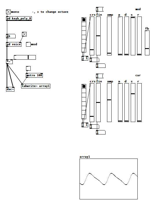
Note that both oscillators are at the same pitch, and I took care to start them at the same time so they'd be in the same phase. I also think you might have accidentally deleted the feedback path for the modulating oscillator. [edit: I see now that you didn't, but the feedback outlet is post amp attenuation, so there is very little feedback. Additionally, you are using s~/r~ which introduces a 64 sample delay--consider using the technique in my next post]
I only have a passing knowledge of FM, but it seems like you have to keep the modulation index (in your case, op2 amp) really low to get the results you're looking for. I don't know how the DX modulation indexes are scaled. Also, if you're evaluting your results in time domain (i.e. looking at the wave shape) I think the phase between the oscillators is important. Adjusting the tuning of the oscillators while they're running will shift their phase relative to each other.
 posted in technical issues
Ninjam external
When I enter a room I see the metronome and a "sync with vst" button. Perhaps the Jam Taba VST thinks PD is another VST? But when I press "sync with vst" PD crashes (and what should it sync to?). Maybe an external would be the only way to sync Pure Data and Ninjam?
 posted in extra~
Converting audio signals to binary with no externals ?
@seb-harmonik.ar , @whale-av Many thanks for help. So what i want to do is this :
i want to have 2 oscillators (both sine waves. one a carry oscillator and the other one a modulator) with different frequency. And i want their audio signal to be processed in [expr~ ] using bitwise XOR modulation. This is different from [+~] , [-~] , [*~] , [/~]. This paper describes this in detail.
Here is a plot of the waveform result using bitwise XOR (from the paper above) :
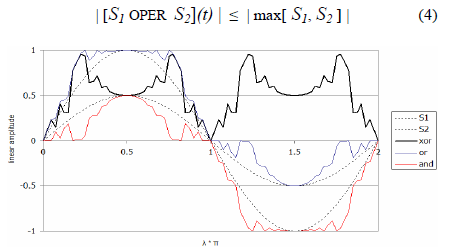
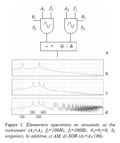
Here is a schematic view of the oscillator structure :
So to control both oscillators i need to control the theta (phase) , f (frequency) and A (linear amplitude). Also S1 is unipolar. So the idea is that i can use the basic operations on the audio signals like (addition,multiplication,bitwise OR,bitwise AND) or i can use something different (bitwise XOR). So i tried to make somehow the bitwise XOR using a formula : bitwise XOR equivalent <- (S1 | S2) - (S1 & S2) (not working). The bitwise operations like "&" and "|" works for [expr] not [expr~].
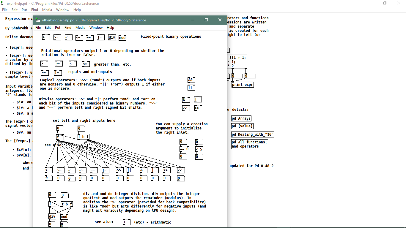
Also i just found this about [expr~ ] object so maybe i am missing something or i am wrong
What is this operator "^" it is bitwise XOR ? or exponential ? or something else ?
Thanks to all a lot for the help. I also tried what @alexandros was talking about and it is almost working. But the waveform is really off so i need to learn more about this idea.
posted in technical issues
Analyzing & Synthesizing a Cowbell
I'm having a hard time with one of Farnell's exercises. In Chapter 29 of Designing Sound, he shows you how to synthesize an old telephone bell and in Exercise 2 he says to do your own analysis of tubular bells, cowbells or Tibeten singing bowls. I chose cowbell and found a sample online. I had it analyzed in SPEAR and Sonic Visualizer:
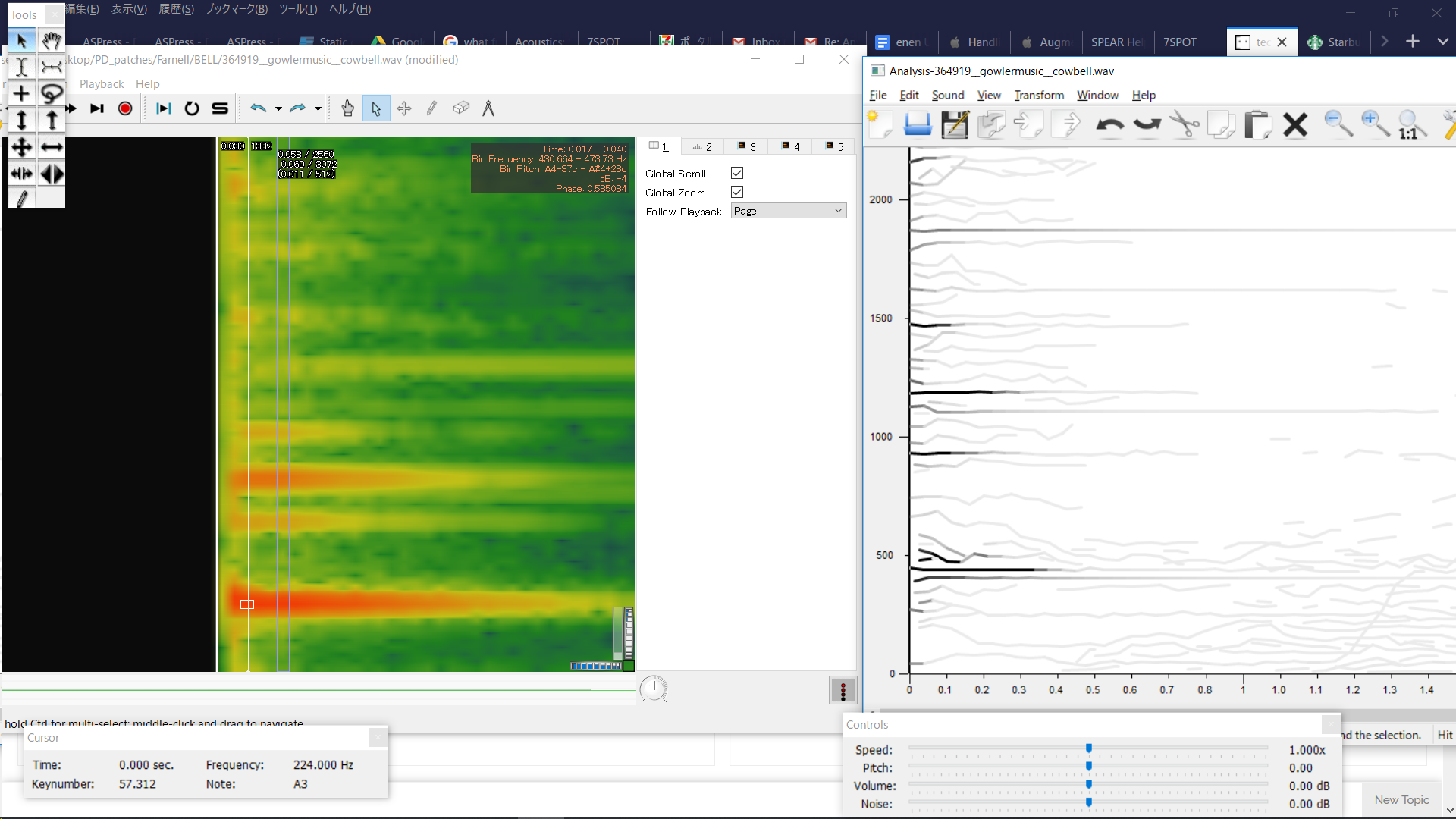
In SPEAR, some frequencies stand out more than others, which seems helpful- however, the analysis lacks detail and there's very little information about amplitudes of frequencies.
In Sonic Visualizer, there's more information, but when I see these thick vertical bands of frequencies, I'm not sure what to do- make very thick clusters with oscillators? That would mean using a lot more oscillators than are in the telephone bell patch and doesn't seem in line with the methodology set forth in the telephone bell patch. I've never used Sonic Visualizer, so it's possible I'm using the wrong analysis layer.
This zip-file contains the following two patches + necessary abstractions:
cowbell - the main patch of my resynthesis. It also has the cowbell sample in an array for comparison.
telephoneBell- Farnell's original patch synthesizing a telephone bell.
For my resynthesis, I mostly chose frequencies based on the SPEAR analysis and then looked up their amplitude with the Sonic Visualizer analysis. I also made the dynamic envelopes steeper than in the telephone bell patch. I can hear that it's wrong, and doing a rudimentary spectral comparison in PD shows that in the model file, there's much more amplitude around the 430Hz and the 1100Hz range. I'm just not sure how to derive the proper values from an analysis and where within those frequency ranges (the thick red-orange lines) I should be placing the oscillators..
Could anyone give me suggestions on how to go about this analysis/resynthesis? I've been fiddling with this/trying different things too long already and feel like I'm not getting anywhere.
 posted in technical issues
Permutations, second part, can anybody get this patch to work?
@Ale-H.H. OK....... You are going to have to trust me on this.
This took about an hour to build........ but you can now expand it in seconds.
Abstractions are a powerful tool......... but to build them you need to understand the use of variables ($0 $1 $2......etc.)..
NEW2.zip
PLEASE NOTE>>!!
Any abstraction can be copied and pasted......... .So if you want more oscillators within a [voice_gen] just copy/paste a [part_voice] within a [voice_gen] and give it a new number [part_voice $1 "x"]...... Change the pasted one's Name to [part_voice $1 "new voice number").......
It will need a timbre curve as well.... so open the relevant [timbre_gen"y"] and put a new [part_timbre $1 $2 "x"] make a new volume curve $1-$2-x by copy/pasting an existing one...draw a new curve....... and save the main [voice_gen] abstraction once you are happy.
BEWARE>>!!
1..... the [timbre_gen"x"] need to be saved individually because they contain the timbre sub-curves. They cannot be used as true abstractions (they must have separate names). If you decide you want a new timbre curve for something then copy and paste an old [timbre_gen"x"], changing its name........ then change the sub-curves and re-save the file.
((this could be done better by writing data out to text files, but I don't have the time now to implement that..... this solution works.......))
2.... If you add more oscillators to a voice then you will end up with some producing ultra-sonics. If you will need to specify some new relationship between the oscillators (other than x2,x3 etc. you can do that by changing the 2nd argument for the oscillators.... i.e. [part_voice $1 0.5] etc.
Don't forget to put the "0.5" in a corresponding [part_timbre] and it's graph....!
HOWEVER>>!!
I cannot help you to do this without abstractions..... it would be too difficult and too messy.
You are absolutely going to have to understand them for a project like this that is going to become very complex very fast.
See here for some help........ https://forum.pdpatchrepo.info/topic/9774/pure-data-noob/4
You will not have wasted your time.
The future benefit will be enormous...... as any sudden new idea for your patch can be working 100% just a few minutes later!.
You should probably print this post before you start playing with the patch.
And please do not despair.
You will, probably after a good nights sleep, have a $ eureka moment...... and from then on you will find patching in Pd as easy as Pi....... or is that Pie?.....
New2.zip should be working...... there is nothing clever or unusual.
I might not get time to help for a couple of days. If I get time to integrate a state saving system then I will integrate each [part_timbre] into each [part_voice] and the patching will become even easier.
You have 2 days to get familiar with this way of working...........
David.
 posted in technical issues
Permutations, second part, can anybody get this patch to work?
@Ale-H.H. I am out tonight..... so no help I'm afraid.
I start to understand.
You can assign curves to what you wish....... so?
Anyway.... the last patch allows you to draw curves for each oscillator controlled by just one iaanix timbre curve.
You just have to decide how each oscillator should respond to that curve to create the timbre.
If you want the first oscillator volume to simply follow the iaanix curve then draw a line in "a" from bottom left to top right.
If you want the last oscillator to do the inverse then draw in "h" a straight line from top left to bottom right.
If you want the second oscillator volume to rise quickly as the iannix curve goes to 0.5 and then fall back to zero as the iannix curve reaches 1 then draw a triangle in "b"
I hope that makes sense.
David.
posted in technical issues