Convert analog reading of a microphone back into sound
@MarcoDonnarumma Unable to see what is contained in the sub-patches I don't know how you have regulated the timing. The incoming messages have no clock as far as I know....... the messages arrive when the socket connection spits them out. I see you are measuring the sample period, but is that averaged or continuously updated?
Is there something in your patch that writes the samples at the correct time?
Maybe you could time stamp them in the sender?...... and then use [tabwrite] to index them correctly.
But are you sending repeated bangs? from [r $0-metroreg].
[tabwrite~] needs just one bang to start and will write at your Pd sample-rate (maybe 44100 samples per second). So maybe your array1 is simply far too small to show the data? You need to choose the arraysize for the time window you want to look at and then bang [tabwrite~] at that rate (new window draw as the last finishes).
If the scope is still "blocky" because of your actual low sample-rate of 500Hz you can interpolate afterwards.
This....... https://support.audient.com/hc/en-us/articles/202587353-Clocking-Explained sort of goes into the subject, but essentially samples in the wrong place introduces distortion and when there is enough distortion all you get is noise.
David.
P.S. Lastly (probably not) a 40Hz signal is inaudible for a lot of people. But with a low sample-rate the waveform will be drawn as blocks rather than a smooth curve (at 44100Hz), and your ears will hear it because of the sharp steps (almost like a square wave) in the waveform.
So maybe your patch is actually fine?
Haha here we go.... you can smooth the samples like this..... https://forum.pdpatchrepo.info/topic/11850/explanation-for-lop-object-in-this-patch-requested/2
.... a sort of "pre-interpolation" if you wish, that will smooth for the higher sample-rate in the [tabwrite~] array.
 posted in technical issues
Creating synths: overall tone
@nuromantix said:
I've been mixing records for 25 years so I'm comfortable with using EQ but surprised by the strange peaks in my Pure Data sounds.
Going back to analog, each internal component of a synth alters the frequency response, the frequency response of the mixer sitting between VCO and VCF has it's input and output frequency response affected by the VCO and VCF it is connected too and in turn it affects the frequency response of the VCOs output circuitry and the frequency response of the VCFs input circuitry. And this frequency response is probably not fixed, as you turn down the mixers volume it may cut some highs and/or even distort the lows which adds frequency content by way of harmonics. Which takes us to the distortion characteristics which are just as complex, dozens of discrete sources adding up and contributing to a complex spectrum. Most digital synths mimic this more complicated frequency response to some degree, either by design or necessity. Pd is ideal and has a dead flat frequency response through the entire chain unless you give it a reason not to have one. If you need to add filtering, than add filtering, not everyone feels the need, it depends on your goals.
 posted in technical issues
Are there any resources on manipulating waveforms in interesting ways, like for example mirroring a waveform along either axis, or something similar to the bend options in serum?
@schitz I would start by using phase distortion. So if you're using a [phasor~] and [tabread4~] to read a table, or if you're using some other method of waveshaping then you can manipulate the [phasor~] that's used to read it.
for instance, this phase distortion will read the 1st half of the wave faster or slower than the 2nd half, depending on the value from the right inlet (that's in a range between 0 and 1). the frequency is from the left inlet:
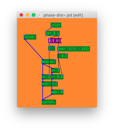
If you want to have it be bandlimited then that will be more involved, especially if using a method besides oversampling
 posted in technical issues
Another modulation technique (experimenting with wavesets)
To be honest, I hadn't tested the patch before I shared it. Which I definately should have, because I just found some serious distortion problems! Not the kind of distortion that you may want, of course ...
The problem is this: In a digital (sampled) signal you can never really find zero-crossings. All you can get is the first sample after the zero crossing. So I had to calculate an imaginary point between the samples n (> 0) and n-1 (< 0) using linear interpolation. The point of zero crossing then is: n - x[n] / (x[n] - x[n-1])
Fortunately, the vline~ object is sub-sample accurate and can handle this!
So here is an improved version of the patch: waveset-experiments-ms.pd
One more problem might be pd's limited precision. But I've never worked with "double precision" and it would probably be an overkill for this kind of problem anyway.
 posted in patch~
Simplesequencer
I posted the Emscripten Website which is based on a Pure Data / Ofelia patch some time ago.
But I made some improvements and would like to get some feedback if there is a large audio latency or if there is a lot of audio distortion with certain browsers, os or devices: https://simplesequencer.handmadeproductions.de/
My experience is, that it works well with the current audio buffersize of 2048 with Firefox and Chrome on my desktop computer (Linux and Windows), and with some distortion on my Android smartphone.
 posted in patch~
Best way to avoid clicks (tabread4~)
Amplitude modulation of any sort, including envelopes, always distorts the spectrum to some extent.
Normally we don't notice because typical sounds have a complex spectrum, which masks the distortion.
But here, you are applying it to an artificially simple spectrum, containing only DC offset. DC offset is silent, and the spectral distortion is not, so there is nothing to cover it.
I generated an audio file with a 30 ms ramp up and 50 ms ramp down. For comparison, I applied this envelope to a sine wave in the right channel. Then I opened this file in Audacity and looked at the spectrogram.
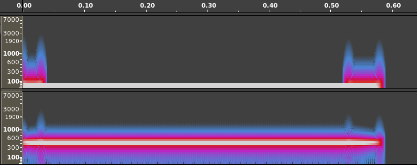
I think it's pretty easy to see here why the envelope might be audible in the case of DC * envelope, but not perceptible in the case of the audible signal * envelope.
Bottom line is, just because you hear spectral distortion in an artificial scenario which you would never encounter with audible signals, doesn't mean that it will be noticeable in real world scenarios.
(Carrying it further: If there is no envelope, there's a risk of an instantaneous transition from non-zero to zero or vice versa. Instantaneous transitions require a lot of high-frequency content, which we hear as a click. A linear transition effectively lowpass-filters the instantaneous transition -- there are still artifacts, but they are relatively low amplitude, and in a frequency range normally occupied by musical tones at a much higher amplitude. A ramp-enveloped sound will never be perfect, but it's better than a rectangular envelope.)
"replaced by something better" -- A sinusoidal envelope shows a smoother spectrogram. You might try that: cos * 0.5 + 0.5 -- from pi to 2pi is your ramp up, 0 to pi is the ramp down.
Edit: You can eliminate the +0.5 by squaring the cos and halving theta, because cos^2 x = cos(2x) * 0.5 + 0.5. Actually cos~, IIRC, scales radians down to 0 .. 1, so you could do line~ --> cos~ --> [*~] (cos~ to both inlets) and drive it by "0.25, 0.5 30" for the ramp up, and "0, 0.25 50" for the ramp down. Haven't verified this at the computer but I think it's right.
hjh
 posted in technical issues
20 mode pole mixing and morphing filter. Updated
@oid said:
I am referring to it being made up from multiple objects instead of just one, analogy between transistors and integrated circuits.
Ok well, I was refering to the inherent phase shift that any digital filter has because of the discrete time and delay. No biggie.
Probably not control vs signal domain since they both have [mtof] on the cutoff so should be set to the exact same frequency. I am not talking about cancellation during the morph, as I said some transitions don't work, a resonance morph from 24db hp to 12db lp works but 24db hp to 18db lp results in the resonance results in the wrong phase after the morph, but a morph from 12db lp to 18db lp works just fine (don't recall if those actual transitions are the troublesome ones, just a random example). I suspect an error that can only be seen on the text level, order of operations (don't see anywhere this could be the issue) or an actual error which can not be seen in the patcher like the duplicate patch cable bug. I am fairly certain this just recently cropped up and the non-[lop~] filters did work but that might have just been an illusion caused by the mysterious 10 sample delay which had cropped up some how, I have no idea, hence starting over from scratch come weekend.
For resonance to work, there has to be a full 360 degree shift of the cut-off frequency while the other frequencies get cancelled/phased out. This works when you have 4 1 pole filters doing 45 degrees shift on the cutoff frequency each and then do negative (180 degree shift) feedback. But when you start mixing the different poles for the feedback you get all sorts of different phase distortions that wont create the magic self oscillation we love so much. Maybe try using the [filter-graph] abstractions from H10.measurement.pd to measure phase distortion on your resonance pole-mix and see what is going on.
As an aside, know of any suitable externals which is essentially [lop~] with signal rate? I looked some but only found more complex filters, would be nice to have that CPU savings which [lop~] provides but keep signal rate inputs. Or is the CPU difference primarily the signal rate cutoff? Seems too great to be just that.
I just ran a test on [rpole~] vs [lop~] (seppareately!)
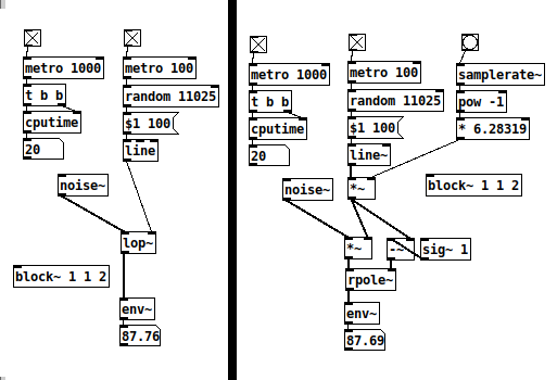
Setting [rpole~] up like here, it works 'exactly* like [lop~]. They both spike at 30 CPU but stay at 20 most of the time. I think [rpole~] is as cheap as it gets with signal rate cut-off control. Of course, small differences add up when you have several instances.
 posted in abstract~
Reversing/Inverting Sawtooth alters the sound?
@Booberg Slew rate in electronics does not itself alter phase (arguable) as it is a byproduct, but there are countless things in most circuits which do alter phase. We use capacitors to block the DC voltages between different stages of the circuit so the DC voltages which set operating points for those stages don't interact with each other and alter the operating point of the other, these capacitors form filters with the resistances around them, phase is a much more fluid thing in the real world and less perfect than in the digital world. Sometimes we design out these capacitors to avoid these effects and directly couple the various stages in a circuit but this creates a teeter totter effect, altering one stage affects the others so you have to adjust them all and rebalance everything. But slew rate is not an issue in something like the transistor ladder since its effects will be insignificant compared to the effects of the filter unless the the cutoff is all the way up and Q all the way down and even then would likely be lost behind the circuits distortion and noise.
I do not know of any really good software transistor ladders, most if not all mimic the circuit as a whole instead of the individual stages which make up the circuit, this largely removes the highly interactive nature of the the stages and the controls but it is more CPU efficient and makes the filter respond as most people expect a filter to respond. The filter has four major components from the audio standpoint, input amp, the transistor ladder itself, the recovery/output amp, and the resonance path, each of these tailors the frequency response and distortion characteristic of the overall circuit and each of these influences how the others do this. Generally the primary source of distortion is the output amp loading down the ladder, but we can also overdrive the input for a different sound and high resonance settings will overdrive the ladder itself, changing the filters frequency can completely remove the distortion effects of the output amp and make the other sources primary and they each have a very different sort of distortion. We have four distinct sources of distortion and tone shaping besides the ladder at the core and all but the input circuitry are affected to some degree by the cutoff control voltage since changing the cutoff changes how the ladder loads the output amp which changes how the resonance path drives the core and loads the output stage. I know of no emulations which bothers to model all of this, they seem to all fixate on getting that handful of stereotypical sounds and call it good because they know that the first thing most people are going to do is set it for one of those sounds and if it gets that sound they will be convinced of it's authenticity, most have not spent enough time with the real thing or done extensive analysis of the circuit, they only know those stereotypical sounds, not how it responds to the musician.
Edit: I don't know if any of this actually matters or if anyone would notice the difference between the simplified emulations and an accurate one, musicians tend to be more practical than engineers and the practicality of my musician side lost out to my curiosity in such matters long ago. The real thing does respond much more like an acoustic instrument than an electronic instrument, which is why the mini was the first big success in synths, but I am not sure that plays any role these days.
LTSpice may be available for OSX, I don't actually know now that I think about it, if you have wine installed the windows version runs perfectly there. Check their site, it is free. I do not believe you would be able to run its circuits with other simulators but I could be wrong, the file syntax might just be plain old Spice.
posted in Off topic
Reversing/Inverting Sawtooth alters the sound?
@Booberg In ear monitors are not going to give you and accurate representation and will certainly exaggerate such effects, they are not designed for quality, they are designed to make sure you can hear what is going on on stage without the issues caused by stage monitors, don't have to worry about walking out of their beam.
Slew is one of the many things which is largely ignored by programmers so there is scant information from that standpoint, but any decent electronics book will have plenty on the subject and every opamp data sheet will have it speced. It is pretty simple for the most part and you can do a good job mimicking it with [lop~], just set the frequency to the amount of slew you want. This will not get you anywhere near the transistor ladder sort of distortion, especially the early mini/modular transistor ladder sort of distortion which is caused by the ladder loading down the output stage, this creates a highly frequency dependent distortion which varies with cutoff and Q. Later transistor ladders and the ARP variation have a much simpler distortion which is largely your standard clipping distortion and not as musical/natural but more versatile/less restricting. A few years back I designed a distortion pedal around the mini transistor ladder, this weekend I will see if I still have my notes and send them your way if I do, I did a fairly extensive study of it's distortion characteristics and the various sources, should help you. I probably have my LTSpice models for it all, so if you run windows or have wine installed I can send you those as well which will give you very detailed information regarding it all.
posted in Off topic
Trying to reproduce a sound with Pd
@jameslo Analog components all have tolerances, +- 10% is not uncommon for pots, so any of the knobs between the two modules could be 20% off from each other given a worse case scenario, plus all those other components in the module could make it even further off, Generally circuits are designed to minimize the effects of component tolerances and high tolerance parts will be used in critical locations like frequency but amplitude and PW are not critical location, our ears will not notice small differences here. On top of that components age and their value changes, so two 30 year old modules can be very different despite once being identical. Things like phase and frequency are not constants in the analog world, things drift and oscillators which share a power source tend to sync when they get close. Most have to be very close in frequency to sync this way, the beat frequency will be well under 1hz but under certain situations you can hear it if you listen close. When trying to copy a patch from the analog world in the digital, knobs can only be used as a rough guide, need to use your ears.
When you distorted the wave you added harmonics and changed the strengths of the old harmonics, only harmonics of equal strength but opposite phase will cancel fully. You most likely did have cancellation just not full cancellation (depends on how you distorted it). Put both oscillators to the same frequency and opposite phase, listen to the distorted one and then add in the undistorted oscillator, you should hear a decrease in harmonic content from the cancellation. This will be most apparent with low to moderate levels of distortion, the more distortion, the more harmonics you are adding, the less the two waves have in common, and as a result less gets canceled.
Edit: didn't quite finish that last sentence.
posted in patch~