JASS, Just Another Synth...Sort-of, codename: Gemini (UPDATED: esp with midi fixes)
JASS, Just Another Synth...Sort-of, codename: Gemini (UPDATED TO V-1.0.1)
jass-v1.0.1( esp with midi fixes).zip
1.0.1-CHANGES:
- Fixed issues with midi routing, re the mode selector (mentioned below)
- Upgraded the midi mode "fetch" abstraction to be less granular
- Fix (for midi) so changing cc["14","15","16"] to "rnd" outputs a random wave (It has always done this for non-midi.)
- Added a midi-mode-tester.pd (connect PD's midi out to PD's midi in to use it)
- Upgrade: cc-56 and cc-58 can now change pbend-cc and mod-cc in all modes
- Update: the (this) readme
INFO: Values setting to 0 on initial cc changes is (given midi) to be expected.
JASS is a clone-based, three wavetable, 16 voice polyphonic, Dual-channel synth.
With...
- The initial, two wavetables combined in 1 of 5 possible ways per channel and then adding those two channels. Example: additive+frequency modulation, phase+pulse-modulation, pulse-modulation+amplitude modulation, fm+fm, etc
- The third wavetable is a ring modulator, embedded inside each mod type
- 8 wave types, including a random with a settable number of partials and a square with a settable dutycycle
- A vcf~ filter embedded inside each modulation type
- The attack-decay-release, cutoff, and resonance ranges settable so they immediately and globally recalculate all relevant values
- Four parameters /mod type: p1,p2, cutoff, and resonance
- State-saving, at both the global level (wavetables, env, etc.), as well as, multiple "substates" of for-each-mod-type settings.
- Distortion, reverb
- Midiin, paying special attention to the use of 8-knob, usb, midi controllers (see below for details)
- zexy-limiters, for each channel, after the distortion, and just before dac~
Instructions
Requires: zexy
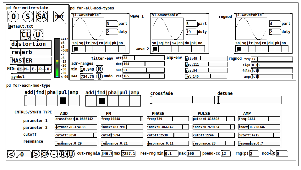
for-entire-state
- O: Open preset. "default.txt" is loaded by...default
- S: Save preset (all values incl. the multiple substates) (Note: I have Not included any presets, besides the default with 5 substates.)
- SA: Save as
- TEST: A sample player
- symbol: The filename of the currently loaded preset
- CL: Clear, sets all but a few values to 0
- U: Undo CL
- distortion,reverb,MASTER: operate on the total out, just before the limiter.
- MIDI (Each selection corresponds to a pgmin, 123,124,125,126,127, respectively, see below for more information)
- X: Default midi config, cc[1,7,8-64] available
- M: Modulators;cc[10-17] routed to ch1&ch2: p1,p2,cutoff,q controls
- E: Envelopes; cc[10-17] routed to filter- and amp-env controls
- R: Ranges; cc[10-17] routed to adr-min/max,cut-off min/max, resonance min/max, distortion, and reverb
- O: Other; cc[10-17] routed to rngmod controls, 3 wavetypes, and crossfade
- symbol: you may enter 8 cc#'s here to replace the default [10-17] from above to suit your midi-controller's knob configuration; these settings are saved to file upon entry
- vu: for total out to dac~
for-all-mod-types
- /wavetable
- graph: of the chosen wavetype
- part: partials, # of partials to use for the "rn" wavetype; the resulting, random sinesum is saved with the preset
- duty: dutycycle for the "du" wavetype
- type: sin | square | triangle | saw | random | duty | pink (pink-noise: a random sinesum with 128 partials, it is not saved with the preset) | noise (a random sinesum with 2051 partials, also not saved)
- filter-env: (self-explanatory)
- amp-env: (self-explanatory)
- rngmod: self-explanatory, except "sign" is to the modulated signal just before going into the vcf~
- adr-range: min,max[0-10000]; changing these values immediately recalculates all values for the filter- and amp-env's scaled to the new range
- R: randomizes all for-all-mod-types values, but excludes wavetype "noise"; rem: you must S or SA the preset to save the results
- U: Undoes R
for-each-mod-type
- mod-type-1: (In all cases, wavetable1 is the carrier and wavetable2 is the modulator); additive | frequency | phase | pulse | amplitude modulation
- mod-type-2: Same as above; mod-type-2 May be the same type as mod-type-1
- crossfade: Between ch1 and ch2
- detune: Applied to the midi pitch going into ch2
- for-each-clone-type controls:
- p1,p2: (self-explanatory)
- cutoff, resonance: (self-explanatory)
- navigation: Cycles through the saved substates of for-each-mod-type settings (note: they are lines on the end of a [text])
- CP: Copy the current settings, ie. add a line to the end of the [text] identical to the current substate
- -: Delete the current substate
- R: Randomize all (but only a few) substate settings
- U: Undo R
- cut-rng: min,max[0-20000] As adr-range above, this immediately recalculates all cutoff values
- res-rng: min,max[0-100], same as previously but for q
- pbend: cc,rng: the pitchwheel may be assigned to a control by setting this to a value >7 (see midi table below for possibilities); rng is in midi pitches (+/- the value you enter)
- mod-cc: the mod-wheel may be assigned to a control [7..64] by setting this value
midi-implementation
| name | --- | Description |
|---|---|---|
| sysex | not supported | |
| pgmin | 123,124,125,126,127; They set midi mode | |
| notein | 0-127 | |
| bendin | pbend-cc=7>pitchbend; otherwise to the cc# from below | |
| touch | not supported | |
| polytouch | not supported |
cc - basic (for all midi-configs)
| # | name | --- | desciption |
|---|---|---|---|
| 1 | mod-wheel | (assignable) | |
| 7 | volume | Master |
cc - "X" mode/pgmin=123
| cc | --- | parameter |
|---|---|---|
| 8 | wavetype1 | |
| 9 | partials 1 | |
| 10 | duty 1 | |
| 11 | wavetype2 | |
| 12 | partials 2 | |
| 13 | duty 2 | |
| 14 | wavetype3 | |
| 15 | partials 3 | |
| 16 | duty 3 | |
| 17 | filter-att | |
| 18 | filter-dec | |
| 19 | filter-sus | |
| 20 | filter-rel | |
| 21 | amp-att | |
| 22 | amp-dec | |
| 23 | amp-sus | |
| 24 | amp-rel | |
| 25 | rngmod-freq | |
| 26 | rngmod-sig | |
| 27 | rngmod-filt | |
| 28 | rngmod-amp | |
| 29 | distortion | |
| 30 | reverb | |
| 31 | master | |
| 32 | mod-type 1 | |
| 33 | mod-type 2 | |
| 34 | crossfade | |
| 35 | detune | |
| 36 | p1-1 | |
| 37 | p2-1 | |
| 38 | cutoff-1 | |
| 39 | q-1 | |
| 40 | p1-2 | |
| 41 | p2-2 | |
| 42 | cutoff-2 | |
| 43 | q-2 | |
| 44 | p1-3 | |
| 45 | p2-3 | |
| 46 | cutoff-3 | |
| 47 | q-3 | |
| 48 | p1-4 | |
| 49 | p2-4 | |
| 50 | cutoff-4 | |
| 51 | q-4 | |
| 52 | p1-5 | |
| 53 | p2-5 | |
| 54 | cutoff-5 | |
| 55 | q-5 | |
| 56 | pbend-cc | |
| 57 | pbend-rng | |
| 58 | mod-cc | |
| 59 | adr-rng-min | |
| 60 | adr-rng-max | |
| 61 | cut-rng-min | |
| 62 | cut-rng-max | |
| 63 | res-rng-min | |
| 64 | res-rng-max |
cc - Modes M, E, R, O
Jass is designed so that single knobs may be used for multiple purposes without reentering the previous value when you turn the knob, esp. as it pertains to, 8-knob controllers.
Thus, for instance, when in Mode M(pgm=124) your cc send the signals as listed below. When you switch modes, that knob will then change the values for That mode.
In order to do this, you must turn the knob until it hits the previously stored value for that mode-knob.
After hitting that previous value, it will begin to change the current value.
cc - Modes M, E, R, O assignments
Where [10..17] may be the midi cc #'s you enter in the MIDI symbol field (as mentioned above) aligned to your particular midi controller.
| cc# | --- | M/pgm=124 | --- | E/pgm=125 | --- | R/pgm=126 | --- | O/pgm=127 |
|---|---|---|---|---|---|---|---|---|
| 10 | ch1:p1 | filter-env:att | adr-rng-min | rngmod:freq | ||||
| 11 | ch1:p2 | filter-env:dec | adr-rng-max | rngmod:sig | ||||
| 12 | ch1:cutoff | filter-env:sus | cut-rng-min | rngmod:filter | ||||
| 13 | ch1:q | filter-env:re | cut-rng-max | rngmod:amp | ||||
| 14 | ch2:p1 | amp-env:att | res-rng-min | wavetype1 | ||||
| 15 | ch2:p2 | amp-env:dec | res-rng-max | wavetype2 | ||||
| 16 | ch2:cutoff | amp-env:sus | distortion | wavetype3 | ||||
| 17 | ch2:q | amp-env:rel | reverb | crossfade |
In closing
If you have anywhere close to as much fun (using, experimenting with, trying out, etc.) this patch, as I had making it, I will consider it a success.
For while an arduous learning curve (the first synth I ever built), it has been an Enormous pleasure to listen to as I worked on it. Getting better and better sounding at each pass.
Rather, than say to much, I will say this:
Enjoy. May it bring a smile to your face.
Peace through love of creating and sharing.
Sincerely,
Scott
 posted in patch~
Self-listening app
Once again -- probably the distortion is coming from outside of Pd.
The signal flow is like this:
-
The mic converts air pressure variations into an analog electrical signal.
-
A pre-amplifier in the soundcard adjusts the volume in the analog domain.
-
The ADC converts the analog signal to digital.
-
The OS pipes the digital signal to Pd.
My guess is that the signal is too loud at #2. If so, then the ADC (#3) will produce a distorted (clipped) signal. After this -- understand this clearly -- there is nothing you can do in the digital domain to fix it.
It's critical to be sure the recording volume in the soundcard is set correctly. The recording volume must be adjusted before sampling. Pd gets the audio after sampling, so your patch can't do anything about it.
I'd actually said this a week ago but, glancing over the thread, nowhere does anybody say "I set the mic level." So I think probably you haven't done it... but this is the first thing to check when a mic is distorting.
If it's a built-in soundcard, the volume will be a system setting. If it's an external soundcard, it will be a knob on the external unit.
hjh
 posted in technical issues
Self-listening app
there is some delay (small, but big enough to bother) between the input and the output,
There is always delay in computer audio systems. The only solution is to reduce the audio hardware driver buffer size, which must be done outside of Pd.
Distortion: If the mic input is too hot, then the audio will be distorted in the soundcard. There's nothing any software can do to fix that. I can say categorically that Pd will do nothing to distort an in-range signal coming in, unless you ask it to... so if you're just passing input to output and getting distortion, then it's likely that the input is distorted.
Unfortunately the exact solution will depend on the type of mic being used and how it's connected. If it's a cheap headset mic or phone earpiece connected to the built-in 1/8" jack, you might try the system control panel and look for a mic level setting.
hjh
PS Edit: Didn't see the previous reply!
posted in technical issues
Same loudness when using a FX (ie: disto)
A long time ago I did a patch that was able to keep the same loudness (perceptible) when applying a FX. The most obvious FX was a distortion. I lost the patch and I tried to redo it using env~ but it's not working like before.
So something like that:
[inlet~]
|      |
|      [check loudness average]
[FX (distortion)]
|
[apply same loudness as inlet~]
|
[dac~]
Of course sometimes it's good to have a boost in loudness when applying a distortion, so I will fine-tune this method. Maybe I should consider using a compressor instead?
Thanks
 posted in technical issues
time stamped events tracking
Making an "event sequencer" for a project. Events come in as tag / value pairs, such as "distortion 0.75", "reverb_onOff 1", etc
the timing of these events is tracked, 256 steps per loop.
so, need to make some sort of container that can be filled with these tag / value pairs, going into the appropriate step slot.
For example, on step 156, there might be movement of the GUI for both "distortion" and "reverb_onOff", so both those events should go into step 156 slot.
a final structure might look something like this:
step156 distortion 0.75
step156 reverb_onOff 1
step157 blank
step158 blank
step159 reverb_onOff 0
step159 chorus 0.23
etc,
Any ideas on a way to do this, preferably in vanilla pd, but perhaps open to externals if they may do it better?
 posted in technical issues
Unexpected noises appear when playing score
@whale-av I like this distortion, its exactly what i had in mind 1:37
here is the patch from his blog (Isaac 139)distortion, isaac 139.zip
 posted in technical issues
Sound distorts when going through send~ and receive~
I'm fairly new to Pure Data, though I'm excited by what I've learned so far. I followed this tutorial -- http://designingsound.org/2013/04/pure-data-wavetable-synth-part-1/ -- up through the second-to-last step (with some adjustments for things that didn't quite work when I followed them in the tutorial), and then began modifying it to add more modulation and other features I wanted. I'm currently trying to implement what I'm thinking of as "suboscillators" that will be able to be tuned in relation to the main oscillator, mixed in with it, modulate pitch and amplitude, and take their own envelopes. I also want the suboscillators to be able to take modulation from either of the two "LFO"s [in quotes since the first LFO actually outputs in the audible range] (adding a second to what's specified in the tutorial, along with additional layers of LFOs below them), so I've been moving things around and redesigning the patch a little bit, breaking it off and on, and trying to get it working again.
While working on this, I noticed a behavior that's baffling me: the signal of the first LFO appears to distort when sent out through send~ and then back in through receive~. If I connect the output of the LFO directly to dac~, it sounds fine. Sent through send~ and back through receive~ and then to dac~ and it sounds louder and there are some other frequencies seemingly present, as if it's maybe clipping a little bit. I thought that send~ and receive~ were functionally the same as just using connector cords, so I'm seriously confused by this. For the purposes of the patch, having the LFO signal distort is not good, so I feel like I need to figure this out before I go forward with the features I want to implement. Being new, I imagine it's something simple I'm overlooking.
Here's a link to part of the patch where the problem is occurring: http://imgur.com/a/GkRUI I haven't tested yet to figure out if other send~ receive~ pairs are causing distortion. Any clarification or ideas about why this is happening would be much appreciated.
[edit: There's also apparently an error message going along with this: "consistency check failed: signal_free 3" I thought it was some other part of the larger patch generating the error, but I copied just the LFO generator section to a separate patch to play with, and that message still appears in the console. The weird distortion with receive~ still occurs too.]
 posted in technical issues
Subwoofer Servo Controller
@yaguirre As far as I know there is no way to have "realtime" in a computer. I suppose for a 50Hz signal you can get close enough. They have chosen 50Hz (narrow band filter) and applied a negative feedback loop to the signal from the output of an accelerometer which is only an approximation to the actual pressure wave produced. They are then surprised that having applied negative feedback at 50Hz the output level at 50Hz is reduced and that there is less distortion at that lower drive voltage. Their successful waveform has slower attack (negative feedback) and faster decay (idem) and no longer resembles a sine wave. Most of their distortion is probably from the box resonance at the higher spl.
Anyway, using asio or core audio you can get down to 2ms latency in Pd (if you are not doing too much work) which is the same as a professional mixing desk.
You can check your patch with an impulse and count the samples to work out how much extra latency you are adding to that 2ms (2 feet of air).
They do say in their paper that they had to use "analogue" though!
Sub-woofer distortion can be avoided by using 2 drivers, one facing backwards and connected out of phase (so pushing the same way). All of the artefacts of the speakers are cancelled out at these frequencies. A dipole system and an amplifier with enough current reserve to control the diaphragms will do the job, but if you want an open box dipole design then you will need to carefully choose your speakers for adequate damping. You can get controlled bass down to 28Hz (-3db) with no harmonics. Check out "Gradient SW63". There are some detailed drawings for building your own on the web, although they are very simple......
David.
 posted in technical issues
Subwoofer Servo Controller
@yaguirre !!Duh!! In Pd you could delay the signal to the speaker so that the correcting "out of phase signal" arrives at the same time as the "delayed" distorted signal.... like for a "feed forward" limiter.
But if the woofer makes a distorted signal then it is already too late to correct that, based on the data from an accelerometer, even if you have no delay (analogue). If the woofer has moved too far, and you try to bring it back within range..... well?.... it has already moved too far!
The only thing you can do is to assess the performance of the woofer using the accelerometer, model that, and then change the input to the woofer permanently so as to reduce distortion. Then you don't need the accelerometer any more. You can do that with a microphone though.
Probably just a decent compressor set up correctly would do the job.
Could you post a link to the white paper? I would put money on it being from Apple and the guys who developed "Logic"!
David.
posted in technical issues
Effects processor/instrument/sampler looper thing
nau, thanks for posting.
I had took a look to that thread... but I didn't read everything.
I downloaded your patchs and tested DistOdrive.pd. It sounds great! (I'm not a guitarist). Congratulations! But I think it is "too much" for my need.
What do I need? Well, as my system will affect my voice or some sounds... I don't need a real-life sounding distort pedal. I need... just a distort FX. Your patchs consume 40% of CPU, each pedal. For my system, that is a murder. Maelstorm distortion patch, from his library, does the same. And that's another tip to have in mind in my system: CPU consumption.
Also, I tried different distortions:
- disto~, written by (c) Alexei Smoli... but it doesn't work or the controls doesn't affect the FX (I don't know why)
- The module DISTORTION from Racko Sifredi (written by Johnatan Noé)... but I'm having troubles with control it. He will send me a lite version.
- Maelstorm's one.
Do you have a lite version of your Distortion patch?
Anyway, multimode.mmb is missing in filterplot.mmb-help.pd. And, tab_add_scalar in DS1-tone_stage~-help.
 posted in patch~