Starting a Pure Data Wiki (Database/Examples Collection)
Another sample from the work-in-progress ...
https://docs.google.com/document/d/1tzS2KU8x31JXoUxmkEr5WikJvxcrgHa4C0vM8LBw49Q
I thought it would be worth having a category for these more self-contained collections
Modular Systems in Pd
ACRE
https://git.iem.at/pd/acre
ARGOPd
http://gerard.paresys.free.fr/ARGOPd/
Automatonism
https://www.automatonism.com/
Context
https://github.com/LGoodacre/context-sequencer
https://contextsequencer.wordpress.com/
DENSO
https://www.d-e-n-s-o.org/pure
DIY
http://pdpatchrepo.info/patches/patch/76
Kraken - Virtual Guitar Effects Pedal Board
https://forum.pdpatchrepo.info/topic/11999/kraken-a-low-cpu-compact-highly-versatile-guitar-effects-stompbox
LWM Rack
http://lwmmusic.com/software-lwmrack.html
La Malinette
http://malinette.info/en/#home
Open toolkit for hardware and software interactive art-making systems
Mandril Boxes
http://musa.poperbu.net/index.php/puredata-mainmenu-50#mandril
Metastudio
http://www.sharktracks.co.uk/html/software.html
Muselectron Studio
http://www.muselectron.it/MuselectronStudio/Studio_index.html
NetPd
http://www.netpd.org
NoxSiren
https://forum.pdpatchrepo.info/topic/13122/noxsiren-modular-synthesizer-system-v10
Pd Modular Synthesizer
https://github.com/chrisbeckstrom/pd_modular_synth
Pd-Modular
https://github.com/emssej/pd-modular
PdRacks
https://github.com/jyg/pdr
Proceso
https://patchstorage.com/proceso/
Universal Polyphonic Player (UPP)
https://grrrr.org/research/software/upp/
https://github.com/grrrr/upp
VVD - Virtual (Virtual) Devices
http://www.martin-brinkmann.de/pd/vvd.zip
“a virtual modular-rack” from http://www.martin-brinkmann.de/pd-patches.html
XODULAR
https://patchstorage.com/xodular/
A previous incarnation of Automatonism
any others that should be in there?
 posted in Off topic
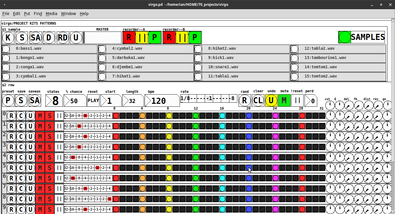
Just Another (Drum) Sequencer...SortOf, codename: Virgo
Just Another (Drum) Sequencer...SortOf, codename: Virgo
REQUIRES: zexy, moonlib, tof (as of Pd 0.50.2, all of which are in deken) and hcs (which comes by default with Pd 0.50.2 and is in deken (for extended))
Special Features
- Unique playhead per row; each with their own metro (beat)
- Up to 8 Volume states-per-beat (by clicking multiple times on the bang; where an rms=1 is divide among the states (2 states:0=rms=0(black), 1=rms=1(red); 3 states:rms=[0|0.5|1])
- Design approach: using creation arguments to alias abstractions, so subsequently they are referred to by their creation arguments, ex. in [KITS sample] sample is referred to as [$1]; which is how they are listed below)
(notes: what I learned experimenting with this design approach, I will share as a separate post. Currently, it does not include cut-copy-paste (of regions of the pattern)). I good way to start trying it out is clicking the "R" to get a random kit and a random pattern).
virgo:[virgo/PROJECT KITS PATTERNS]
- PROJECT[KITS PATTERNS]
- $1:[KITS sample]
- GUI
- K: openpanel to load a previously saved *.txt (text object) kit of samples; on loadbang the default.txt kit is loaded
- S: save the current set of samples to the most recently opened *.txt (kit) preset
- SA: saveas a *.txt of the current set of samples
- D: foldererpanel a sample directory to load the first (alphabetically) 16 samples into the 16 slots
- RD: load a random kit from the [text samples] object where the samples where previously loaded via the "SAMPLES" bang on the right
- U: undo; return to the previously opened or saved *.txt kit, so not the previously randomized
- MASTER: master gain
- (recorder~: of the total audio~ out)
- record
- ||: pause; either recording or play;
- play: output is combined with the sequencer output just before MASTER out to [dac~]
- SAMPLES: folderpanel to load a (recursive) directory of samples for generating random kits
- ABSTRACTIONS
- $1: sample
- bang: openpanel to locate and load a sample for a track
- canvas: filename of the opened sample; filenames are indexed in alignment with track indices in the PATTERNS section
- $1: sample
- GUI
- $2:[PATTERNS row]
- GUI
- P: openpanel to load a previously saved *.txt (pattern) preset file; on loadbang the default.txt pattern is loaded; the preset file includes the beat, pattern, and effect settings for the row
- S: save the current pattern to the most recently opened pattern .txt
- SA: save as (self-explanatory)
- states: the number of possible states [2..8] of each beat;
- %: weight; chance of a beat being randomized; not chance of what it will result in; ex. 100% implies all beats are randomized ; random beats result in a value)gain) between 1 and states-1
- PLAY(reset): play the pattern from "start" or on stop reset all playheads to start
- start: which beat to start the playheads on
- length: how many beats to play [+/-32]; if negative the playheads will play in reverse/from right to left
- bpm: beats-per-minute
- rate: to change the rate of play (ie metro times) by the listed factor for all playheads
- R: randomize the total pattern (incl period and beats, but not the effect settings; beats of 1/32 are not included in the possibilities)
- CL: clear, set all beats to "0", i.e. off
- U: undo random; return to the previously opened or saved preset, ie. not the previous random one
- M: mute all tracks; the playheads continue moving but audio does not come out of any track
- ||:pause all playheads; play will resume from that location when un-paused
- per: period; if 0=randomizes the period, >0 sets the period to be used for all beats
- Edit Mode
- Check the [E] to enter edit mode (to cut, copy, or paste selected regions of the pattern)
- Entering edit mode will pause the playing of the pattern
- Play, if doing so beforehand, will resume on leavng edit mode
- The top-left most beat of the pattern grid will be selected when first entering edit mode
- Single-click a beat to select the top-left corner of the region you wish to cut or copy
- Double-click a beat to select the bottom-right corner
- You may not double-click a beat "less than" the single-clicked (top-left) beat and vice-versa
- Click [CL] to clear your selection (i.e. start over)
- The selected region will turn to dark colors
- If only one beat is selected it will be the only one darkened
- Click the operation (bang) you wish to perform, either cut [CU] or copy [CP]
- Then, hold down the CTRL key and click the top-left corner of where you want to paste the region
- The clicked cell will turn white
- And click [P] to paste the region
- Cut and copied regions may both be pasted multiple times
- The difference being, cutting sets the values (gains) for the originating region to "0"
- Click [UN] to undo either the cut, copy, or paste operation
- Undoing cut will return the gains from 0s to their original value
- Check the [E] to enter edit mode (to cut, copy, or paste selected regions of the pattern)
- (effect settings applied to all tracks)
- co: vcf-cutoff
- Q: vcf-q
- del: delay-time
- fb: delay-feedback
- dist: distortion
- reverb
- gn: gain
- ABSTRACTIONS
- $1: [row (idx) b8] (()=a property not an abstraction)
- GUI
- (index): aligns with the track number in the KITS section
- R: randomize the row; same as above, but for the row
- C: clear the row, i.e. set all beats to 0
- U: undo the randomize; return to the originally opened one, ie. not the previous random one
- M: mute the row, so no audio plays, but the playhead continues to play
- S: solo the row
- (beat): unit of the beat(period); implying metro length (as calculated with the various other parameters);1/32,1/16,1/8, etc.
- (pattern): the pattern for the row; single-click on a beat from 0 to 8 times to increment the gain of that beat as a fraction of 1 rms, where resulting rms=value/states; black is rms=0; if all beats for a row =0 (are black) then the switch for that track is turned off; double-click it to decrement it
- (effects-per-row): same as above, but per-row, ex. first column is vcf-cutoff, second is vcf-q, etc.
- ABSTRACTIONS
- $1: b8 (properties:row column)
- 8-state bang: black, red, orange, yellow, green, light-blue, blue, purple; representing a fraction of rms(gain) for the beat
- $1: b8 (properties:row column)
- GUI
- $1: [row (idx) b8] (()=a property not an abstraction)
- GUI
- $1:[KITS sample]
Credits: The included drum samples are from: https://www.musicradar.com/news/sampleradar-494-free-essential-drum-kit-samples
p.s. Though I began working on cut-copy-paste, it began to pose a Huge challenge, so backed off, in order to query the community as to 1) its utility in the current state (w/o that) and 2) just how important including it really is.
p.p.s. Please, report any inconsistencies (between the instructions as listed and what it does) and/or bugs you may find, and I will try to get an update posted as soon as enough of those have collect.
Love and Peace through sharing,
Scott
 posted in patch~
Few questions about oversampling
Hi,
About a year ago I started to learn a bit pure data in order to create a patch that would act as a groovebox and that should perform on limited cpu resources since I want it to run on a raspberry pi. First I tried to make somekind of fork of the Martin Brinkmann groovebox patch, even if it allowed me to learn a lot about data flow I didn't went to the core of the patch tweaking with sound generation. This led me to end this attempt at forking MNB groovebox patch because even if I could seperate GUI stuff from sound generation and run it on different thread ect... I couldn't go further in optimization in order to reduce the cpu use.
Then a few weeks ago I decided to start again from scratch my project and this time I wanted to be more patient and learn anything needed in order to be capable of optimizing my patch as much as possible. After making a functional drum machine which runs at 2/3% of cpu with 8 different tracks, 126 steps sequencer, a bit of fx ect... I tried to find synths that would opperate well aside the drum machine. And I basicly didn't find any patch that wouldn't use massive amount of cpu time. So I created my own synths, nothing incredible but I'm happy with what I got, though I noticed some aliasing. I read a bit the floss manual about anti aliasing and apply the method used in the manual(http://write.flossmanuals.net/pure-data/antialiasing/), it work well but my synths almost trippled their cpu use, even if I put all my oscilators in the same subpatch in order to use only one instance of oversampling.
I didn't tried to oversample it less than 16 time but since oversampling is so cpu intensive I'm wondering if there's no other option in order to get a good sound definition at a lower cpu cost. I'm already using banlimited waveform so I don't know what I could do in order to limit the aliasing, especialy for my fm patch where bandlimited waveform isn't very useful in order to reduce aliasing.
Since I want to have at least 4 synth track with some at least one synth having 5 voice polyphony I want to know what the best thing to do. Letting FM aside for this project and use switch~ for oversampling 2 or 4 time my synths that use bandlimited waveform ? Or should I try to run different instances of pd for each synth and controling it from a gui/control patch with netsend(though it wouldn't bring down the cpu use at least it would provide somekind of multithreading for my patch) ? Or is there another way to get some antiliasing ? Or should I review lower my expectation because there is no solution that could provide a decent antialiasing for 4 or more synth running at the same time with a low cpu use in pure data in 2021.
Thanks to everyone that would read my topic and try to give some advice in order to get the best antialising/low cpu use solution.
 posted in technical issues
Matrix sequencer - using both Akai APC mini and Akai Midimix
mtrxsequencerbeta1.pd
Hi ! This is pretty beta for know but is working. There are some mistakes like use of subpatches when abstractions would have been better. I’ve been building this kind of matrix sequencer for Akai’s APCmini and Midimix. This requires no externals.
There are two sequences, a green one which goes up to down, from left column to right column
and the red one which goes left to right, from upper line to down line.
The outputs are for each note : the value of the corresponding faders (vertical and horizontal) of each grid’s button.
You can select the 64 buttons of the apc grid, which will output a value only if they’re selected (coloured in yellow), like a trigger. However there is also a trigger unsensitive output.
The midimix 8 first faders are for (from left to right) upper to down lines
the apc 8 first faders are for left to right columns
the 9th fader of midimix is for the lenght of the green sequence, the 9th fader of apcmini is for the length of the red sequence
there are also on the APC 8 buttons for each column and 8 buttons for each lines, there’s a little bug to fix there, as you have to tickle them a bit at the beginning to make them work properly (just press some of the buttons until they light on correctly)
the two sequences are a modulo of the sum of bangs received by the main metro. Modulo of the lenght of each sequence. This sum is multiplied by 1 to 8 thanks to the buttons. And divised by 1 to 8 thanks to these buttons when you also press the last square button which is between those round buttons. So if you multiply by one and divise by two, the sequence will be twice slower. If you multiply by two and divise by one, the sequence will be as fast buy will go from step n to step n+2, n+4 …
The interest here is to create polyrythmical sequences. I,e : red sequence * 5, green sequence *6, both sequences lenght = 60. and things like that. And it’s pretty graphic
okay.
Really sorry for my bad english. Hope this could help/inspire someone. And i would really like returns, as I’m a bit beginning in pd.
I will soon share a new version with abstractions in place of subpatches, in order not to modifiy each subpatches if you want to modifiy something (some places of the patch are 64 repetitions of the same thing, which could be a bit boring to do). mtrxsequencerbeta1.pd
 posted in patch~
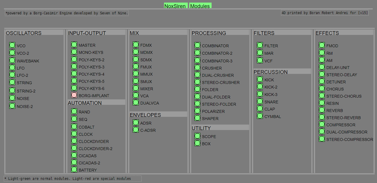
NoxSiren - Modular synthesizer system <- [v15]
NoxSiren is a modular synthesizer system where the punishment of failure is the beginning of a new invention.
--DOWNLOAD-- NoxSiren for :
-
Pure Data :
NoxSiren v15.rar
NoxSiren v14.rar -
Purr Data :
NoxSiren v15.rar
NoxSiren v14.rar
--DOWNLOAD-- ORCA for :
- x64, OSX, Linux :
https://hundredrabbits.itch.io/orca
In order to connect NoxSiren system to ORCA system you also need a virtual loopback MIDI-ports:
--DOWNLOAD-- loopMIDI for :
- Windows 7 up to Windows 10, 32 and 64 bit :
https://www.tobias-erichsen.de/software/loopmidi.html
#-= Cyber Notes [v15] =-#
- added BORG-IMPLANT module.
- introduction to special modules.
- more system testing.
#-= Special Modules [v15] =-#
- BORG-IMPLANT (connects ORCA MIDI system to NoxSiren system)
#-= Current Modules [v15] =-#
- VCO (voltage-controlled-oscillator)
- VCO2 (advance voltage-controlled-oscillator)
- WAVEBANK (additive synthesis oscillator)
- ADSR (Attack-Decay-Sustain-Release envelope)
- C-ADSR (Curved Attack-Decay-Sustain-Release envelope)
- CICADAS (128 steps-Euclidean rhythm generator)
- CICADAS-2 (advance 128-steps polymorphic-Euclidean rhythm generator)
- COMPRESSOR (lookahead mono compressor unit)
- DUAL-COMPRESSOR (2-channel lookahead mono compressor unit)
- STEREO-COMPRESSOR (lookahead stereo compressor unit)
- MONO-KEYS (virtual 1-voice monophonic MIDI keyboard)
- POLY-KEYS-2 (virtual 2-voice polyphonic MIDI keyboard)
- POLY-KEYS-3 (virtual 3-voice polyphonic MIDI keyboard)
- POLY-KEYS-4 (virtual 4-voice polyphonic MIDI keyboard)
- POLY-KEYS-5 (virtual 5-voice polyphonic MIDI keyboard)
- POLY-KEYS-6 (virtual 6-voice polyphonic MIDI keyboard)
- BATTERY (simple manual triggered machine for drumming.)
- REVERB (reverb unit with lowpass control)
- STEREO-REVERB (stereo reverb unit with lowpass control)
- RESIN (advanced rain effect/texture generator)
- NOISE (generates black,brown,red and orange noise)
- NOISE2 (generates yellow,blue,pink and white noise)
- COBALT (6-stage polyrhythm generator)
- SHAPER (basic shaper unit)
- FOLDER (basic wave folding unit)
- STEREO-FOLDER (stereo wave folding unit)
- DUAL-FOLDER (advance wave folding unit)
- POLARIZER (transform a signal into bi-polar, uni-polar, inverted or inverted uni-polar form)
- CLOCK (generates a BPM clock signal for sequencing other modules)
- CLOCKDIVIDER (a clock divider with even division of clock signal)
- CLOCKDIVIDER2 (a clock divider with odd division of clock signal)
- DELAY-UNIT (delay unit)
- STEREO-DELAY (stereo delay unit)
- CHORUS (chorus unit)
- STEREO-CHORUS (stereo chorus unit)
- SEQ (advance 16-step/trigger sequencer)
- KICK (synthesize kick unit)
- KICK2 (synthesize flavor of KICK module)
- KICK3 (synthesize flavor of KICK module)
- SNARE (synthesize snare unit)
- CLAP (synthesize clap unit)
- CYMBAL (synthesize cymbal unit)
- RAND (RNG generator for other modules parameters)
- FMOD (feedback modulation unit)
- AM (amplitude modulation unit)
- RM (ring modulation unit)
- LFO (low-frequency-oscillator)
- LFO2 (advance low-frequency-oscillator)
- COMBINATOR (combine two waves)
- COMBINATOR2 (combine three waves)
- COMBINATOR3 (combine four waves)
- STRING (Karplus-Strong string synthesis unit)
- STRING2 (advance Karplus-Strong string synthesis unit)
- DETUNER (parametric 4-channel detuner unit)
- CRUSHER (basic audio resolution unit)
- STEREO-CRUSHER (basic stereo audio resolution unit)
- DUAL-CRUSHER (advance audio resolution unit)
- FILTER (basic filter)
- VCF (voltage-controlled-filter)
- MAR (Moog-analog-resonant filter)
- VCA (voltage-controlled-amplifier)
- DUAL-VCA (advance voltage-controlled-amplifier)
- FMUX (multiplexer with fast A/D internal envelope)
- MMUX (multiplexer with medium A/D internal envelope)
- SMUX (multiplexer with slow A/D internal envelope)
- FDMX (demultiplexer with fast A/D internal envelope)
- MDMX (demultiplexer with medium A/D internal envelope)
- SDMX (demultiplexer with slow A/D internal envelope)
- MIXER (mix 1-4 possible waves)
- SCOPE (oscilloscope analyzer)
- MASTER (fancy DAC~)
- BOX (useless decorative module)
NoxSiren integrated modules menu system.
 posted in patch~
JASS, Just Another Synth...Sort-of, codename: Gemini (UPDATED: esp with midi fixes)
JASS, Just Another Synth...Sort-of, codename: Gemini (UPDATED TO V-1.0.1)
jass-v1.0.1( esp with midi fixes).zip
1.0.1-CHANGES:
- Fixed issues with midi routing, re the mode selector (mentioned below)
- Upgraded the midi mode "fetch" abstraction to be less granular
- Fix (for midi) so changing cc["14","15","16"] to "rnd" outputs a random wave (It has always done this for non-midi.)
- Added a midi-mode-tester.pd (connect PD's midi out to PD's midi in to use it)
- Upgrade: cc-56 and cc-58 can now change pbend-cc and mod-cc in all modes
- Update: the (this) readme
INFO: Values setting to 0 on initial cc changes is (given midi) to be expected.
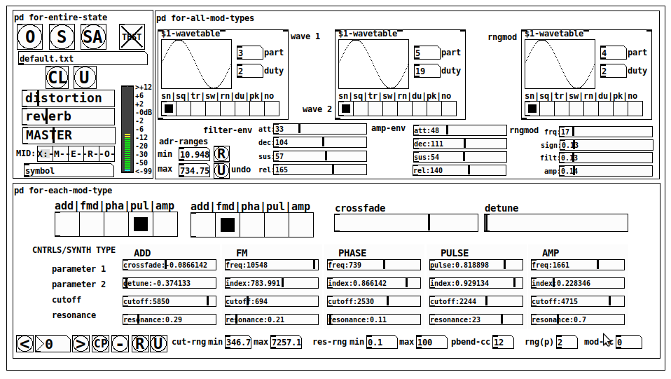
JASS is a clone-based, three wavetable, 16 voice polyphonic, Dual-channel synth.
With...
- The initial, two wavetables combined in 1 of 5 possible ways per channel and then adding those two channels. Example: additive+frequency modulation, phase+pulse-modulation, pulse-modulation+amplitude modulation, fm+fm, etc
- The third wavetable is a ring modulator, embedded inside each mod type
- 8 wave types, including a random with a settable number of partials and a square with a settable dutycycle
- A vcf~ filter embedded inside each modulation type
- The attack-decay-release, cutoff, and resonance ranges settable so they immediately and globally recalculate all relevant values
- Four parameters /mod type: p1,p2, cutoff, and resonance
- State-saving, at both the global level (wavetables, env, etc.), as well as, multiple "substates" of for-each-mod-type settings.
- Distortion, reverb
- Midiin, paying special attention to the use of 8-knob, usb, midi controllers (see below for details)
- zexy-limiters, for each channel, after the distortion, and just before dac~
Instructions
Requires: zexy
for-entire-state
- O: Open preset. "default.txt" is loaded by...default
- S: Save preset (all values incl. the multiple substates) (Note: I have Not included any presets, besides the default with 5 substates.)
- SA: Save as
- TEST: A sample player
- symbol: The filename of the currently loaded preset
- CL: Clear, sets all but a few values to 0
- U: Undo CL
- distortion,reverb,MASTER: operate on the total out, just before the limiter.
- MIDI (Each selection corresponds to a pgmin, 123,124,125,126,127, respectively, see below for more information)
- X: Default midi config, cc[1,7,8-64] available
- M: Modulators;cc[10-17] routed to ch1&ch2: p1,p2,cutoff,q controls
- E: Envelopes; cc[10-17] routed to filter- and amp-env controls
- R: Ranges; cc[10-17] routed to adr-min/max,cut-off min/max, resonance min/max, distortion, and reverb
- O: Other; cc[10-17] routed to rngmod controls, 3 wavetypes, and crossfade
- symbol: you may enter 8 cc#'s here to replace the default [10-17] from above to suit your midi-controller's knob configuration; these settings are saved to file upon entry
- vu: for total out to dac~
for-all-mod-types
- /wavetable
- graph: of the chosen wavetype
- part: partials, # of partials to use for the "rn" wavetype; the resulting, random sinesum is saved with the preset
- duty: dutycycle for the "du" wavetype
- type: sin | square | triangle | saw | random | duty | pink (pink-noise: a random sinesum with 128 partials, it is not saved with the preset) | noise (a random sinesum with 2051 partials, also not saved)
- filter-env: (self-explanatory)
- amp-env: (self-explanatory)
- rngmod: self-explanatory, except "sign" is to the modulated signal just before going into the vcf~
- adr-range: min,max[0-10000]; changing these values immediately recalculates all values for the filter- and amp-env's scaled to the new range
- R: randomizes all for-all-mod-types values, but excludes wavetype "noise"; rem: you must S or SA the preset to save the results
- U: Undoes R
for-each-mod-type
- mod-type-1: (In all cases, wavetable1 is the carrier and wavetable2 is the modulator); additive | frequency | phase | pulse | amplitude modulation
- mod-type-2: Same as above; mod-type-2 May be the same type as mod-type-1
- crossfade: Between ch1 and ch2
- detune: Applied to the midi pitch going into ch2
- for-each-clone-type controls:
- p1,p2: (self-explanatory)
- cutoff, resonance: (self-explanatory)
- navigation: Cycles through the saved substates of for-each-mod-type settings (note: they are lines on the end of a [text])
- CP: Copy the current settings, ie. add a line to the end of the [text] identical to the current substate
- -: Delete the current substate
- R: Randomize all (but only a few) substate settings
- U: Undo R
- cut-rng: min,max[0-20000] As adr-range above, this immediately recalculates all cutoff values
- res-rng: min,max[0-100], same as previously but for q
- pbend: cc,rng: the pitchwheel may be assigned to a control by setting this to a value >7 (see midi table below for possibilities); rng is in midi pitches (+/- the value you enter)
- mod-cc: the mod-wheel may be assigned to a control [7..64] by setting this value
midi-implementation
| name | --- | Description |
|---|---|---|
| sysex | not supported | |
| pgmin | 123,124,125,126,127; They set midi mode | |
| notein | 0-127 | |
| bendin | pbend-cc=7>pitchbend; otherwise to the cc# from below | |
| touch | not supported | |
| polytouch | not supported |
cc - basic (for all midi-configs)
| # | name | --- | desciption |
|---|---|---|---|
| 1 | mod-wheel | (assignable) | |
| 7 | volume | Master |
cc - "X" mode/pgmin=123
| cc | --- | parameter |
|---|---|---|
| 8 | wavetype1 | |
| 9 | partials 1 | |
| 10 | duty 1 | |
| 11 | wavetype2 | |
| 12 | partials 2 | |
| 13 | duty 2 | |
| 14 | wavetype3 | |
| 15 | partials 3 | |
| 16 | duty 3 | |
| 17 | filter-att | |
| 18 | filter-dec | |
| 19 | filter-sus | |
| 20 | filter-rel | |
| 21 | amp-att | |
| 22 | amp-dec | |
| 23 | amp-sus | |
| 24 | amp-rel | |
| 25 | rngmod-freq | |
| 26 | rngmod-sig | |
| 27 | rngmod-filt | |
| 28 | rngmod-amp | |
| 29 | distortion | |
| 30 | reverb | |
| 31 | master | |
| 32 | mod-type 1 | |
| 33 | mod-type 2 | |
| 34 | crossfade | |
| 35 | detune | |
| 36 | p1-1 | |
| 37 | p2-1 | |
| 38 | cutoff-1 | |
| 39 | q-1 | |
| 40 | p1-2 | |
| 41 | p2-2 | |
| 42 | cutoff-2 | |
| 43 | q-2 | |
| 44 | p1-3 | |
| 45 | p2-3 | |
| 46 | cutoff-3 | |
| 47 | q-3 | |
| 48 | p1-4 | |
| 49 | p2-4 | |
| 50 | cutoff-4 | |
| 51 | q-4 | |
| 52 | p1-5 | |
| 53 | p2-5 | |
| 54 | cutoff-5 | |
| 55 | q-5 | |
| 56 | pbend-cc | |
| 57 | pbend-rng | |
| 58 | mod-cc | |
| 59 | adr-rng-min | |
| 60 | adr-rng-max | |
| 61 | cut-rng-min | |
| 62 | cut-rng-max | |
| 63 | res-rng-min | |
| 64 | res-rng-max |
cc - Modes M, E, R, O
Jass is designed so that single knobs may be used for multiple purposes without reentering the previous value when you turn the knob, esp. as it pertains to, 8-knob controllers.
Thus, for instance, when in Mode M(pgm=124) your cc send the signals as listed below. When you switch modes, that knob will then change the values for That mode.
In order to do this, you must turn the knob until it hits the previously stored value for that mode-knob.
After hitting that previous value, it will begin to change the current value.
cc - Modes M, E, R, O assignments
Where [10..17] may be the midi cc #'s you enter in the MIDI symbol field (as mentioned above) aligned to your particular midi controller.
| cc# | --- | M/pgm=124 | --- | E/pgm=125 | --- | R/pgm=126 | --- | O/pgm=127 |
|---|---|---|---|---|---|---|---|---|
| 10 | ch1:p1 | filter-env:att | adr-rng-min | rngmod:freq | ||||
| 11 | ch1:p2 | filter-env:dec | adr-rng-max | rngmod:sig | ||||
| 12 | ch1:cutoff | filter-env:sus | cut-rng-min | rngmod:filter | ||||
| 13 | ch1:q | filter-env:re | cut-rng-max | rngmod:amp | ||||
| 14 | ch2:p1 | amp-env:att | res-rng-min | wavetype1 | ||||
| 15 | ch2:p2 | amp-env:dec | res-rng-max | wavetype2 | ||||
| 16 | ch2:cutoff | amp-env:sus | distortion | wavetype3 | ||||
| 17 | ch2:q | amp-env:rel | reverb | crossfade |
In closing
If you have anywhere close to as much fun (using, experimenting with, trying out, etc.) this patch, as I had making it, I will consider it a success.
For while an arduous learning curve (the first synth I ever built), it has been an Enormous pleasure to listen to as I worked on it. Getting better and better sounding at each pass.
Rather, than say to much, I will say this:
Enjoy. May it bring a smile to your face.
Peace through love of creating and sharing.
Sincerely,
Scott
posted in patch~
Conceptual question about Step Sequencer using Tables, Arrays instead of text files
@nicnut storing the patterns in memory will probably take more ram but definitely less load time when changing patterns
I guess the best way is to use [array define -k] if you don't need to store an infinite # of possible patterns. Here's a version with arrays for up to 64 patterns (64 patterns X 64 steps = 4096 steps for each [array define])
In this version, every time you click a toggle it will save that value in the array (so there is no "reloading the current pattern" and all edits are destructive, in order to do reloadable current patterns you might want to have a current-pattern array or position in the global array that you copy the current pattern into, so when you want to reload the pattern you could just re-copy it)
 posted in technical issues
Converting audio signals to binary with no externals ?
@Jona Thanks again for the idea. This concept can be extended into something really interesting. I was thinking that it is possible to connect a counter that counts N steps and at different steps could replace the values of a particular parameter in a sequential manner with a specific pattern parameter. So you have a polymorphic formula where each parameter $f2,$f3,$f4 is replace by a pattern sequence at different steps. The pattern sequence loading into the formula can be started at a random step in one of the sequencers. Or modulated by other sequencers to be set at a specific step. So you could have one of the sequencers to decide the step value for another sequencer. You could use the gap between steps to hold a specific value in the formula.
<this is just one sequence for one parameter >
[counter]
|
[sel 0 1 2 3 4]
|
[2] <- at step 0 send a message to $f2 ; at step 1 send a different message to $f2 ...
|
[expr~ ($v1 & $v1 % 255) - ($v1 * $f2 & $v1 >> $f3 & $v1 >> $f4]
PD's scheduler, timing, control-rate, audio-rate, block-size, (sub)sample accuracy,
@Nicolas-Danet said:
control messages and compute audio vectors of the DSP graph are interleaved operations. The internal audio vector size is 64.
[64][control][64][control][64][control][64][control]
Ok, i see.
But I read control messages are first, then audio. f.e. [loadbang] is proceeded before an upcoming audio-block.
And [vline~] is calculated and "drawn" before and "modulating" the *following * audio blocks.
[control][64][control][64][control][64][control][64]
What's happen in a 1 sample reblocked subpatch? In short, instead of compute 1 vector of 64 samples, it computes 64 times following a vector of 1 sample.
And there is no way to change this interval rate of 64?
Is upsampling in a subpatch increasing the computation time-interval of control-messages?
The tricky stuff with real time audio is not to do the things fast, but do things fast at the right time. Wait the sound in, deliver the sound out, compute the next sound and wait. When i benchmark my fork for instance, most of the time is spent in sleeping!
I see. In the analog world it is very different. This is why we have the buffer-latency in digital everywhere:
...incoming audio-samples in blocks, computation, audio out, and again...
And the control-domain every 64 samples.
For me as "user" of PD this is confusing.
So every object with a [v ...] will be sampleaccurate on point in upcoming audio-blocks, as long as it is not needed more often then 64 samples later!??? i.e. as long it is not starting several times in a smaller interval then 64 samples?
 posted in technical issues
PD's scheduler, timing, control-rate, audio-rate, block-size, (sub)sample accuracy,
Hello, 
this is going to be a long one.
After years of using PD, I am still confused about its' timing and schedueling.
I have collected many snippets from here and there about this topic,
-wich all together are really confusing to me.
*I think it is very important to understand how timing works in detail for low-level programming … *
(For example the number of heavy jittering sequencers in hard and software make me wonder what sequencers are made actually for ? lol )
This is a collection of my findings regarding this topic, a bit messy and with confused questions.
I hope we can shed some light on this.


- a)
The first time, I had issues with the PD-scheduler vs. how I thought my patch should work is described here:
https://forum.pdpatchrepo.info/topic/11615/bang-bug-when-block-1-1-1-bang-on-every-sample
The answers where:
„
[...] it's just that messages actually only process every 64 samples at the least. You can get a bang every sample with [metro 1 1 samp] but it should be noted that most pd message objects only interact with each other at 64-sample boundaries, there are some that use the elapsed logical time to get times in between though (like vsnapshot~)
also this seems like a very inefficient way to do per-sample processing..
https://github.com/sebshader/shadylib http://www.openprocessing.org/user/29118
seb-harmonik.ar posted about a year ago , last edited by seb-harmonik.ar about a year ago
• 1
 whale-av
@lacuna An excellent simple explanation from @seb-harmonik.ar.
Chapter 2.5 onwards for more info....... http://puredata.info/docs/manuals/pd/x2.htm
David.
“
There is written: http://puredata.info/docs/manuals/pd/x2.htm
„2.5. scheduling
Pd uses 64-bit floating point numbers to represent time, providing sample accuracy and essentially never overflowing. Time appears to the user in milliseconds.
2.5.1. audio and messages
Audio and message processing are interleaved in Pd. Audio processing is scheduled every 64 samples at Pd's sample rate; at 44100 Hz. this gives a period of 1.45 milliseconds. You may turn DSP computation on and off by sending the "pd" object the messages "dsp 1" and "dsp 0."
In the intervals between, delays might time out or external conditions might arise (incoming MIDI, mouse clicks, or whatnot). These may cause a cascade of depth-first message passing; each such message cascade is completely run out before the next message or DSP tick is computed. Messages are never passed to objects during a DSP tick; the ticks are atomic and parameter changes sent to different objects in any given message cascade take effect simultaneously.
In the middle of a message cascade you may schedule another one at a delay of zero. This delayed cascade happens after the present cascade has finished, but at the same logical time.
2.5.2. computation load
The Pd scheduler maintains a (user-specified) lead on its computations; that is, it tries to keep ahead of real time by a small amount in order to be able to absorb unpredictable, momentary increases in computation time. This is specified using the "audiobuffer" or "frags" command line flags (see getting Pd to run ).
If Pd gets late with respect to real time, gaps (either occasional or frequent) will appear in both the input and output audio streams. On the other hand, disk strewaming objects will work correctly, so that you may use Pd as a batch program with soundfile input and/or output. The "-nogui" and "-send" startup flags are provided to aid in doing this.
Pd's "realtime" computations compete for CPU time with its own GUI, which runs as a separate process. A flow control mechanism will be provided someday to prevent this from causing trouble, but it is in any case wise to avoid having too much drawing going on while Pd is trying to make sound. If a subwindow is closed, Pd suspends sending the GUI update messages for it; but not so for miniaturized windows as of version 0.32. You should really close them when you aren't using them.
2.5.3. determinism
All message cascades that are scheduled (via "delay" and its relatives) to happen before a given audio tick will happen as scheduled regardless of whether Pd as a whole is running on time; in other words, calculation is never reordered for any real-time considerations. This is done in order to make Pd's operation deterministic.
If a message cascade is started by an external event, a time tag is given it. These time tags are guaranteed to be consistent with the times at which timeouts are scheduled and DSP ticks are computed; i.e., time never decreases. (However, either Pd or a hardware driver may lie about the physical time an input arrives; this depends on the operating system.) "Timer" objects which meaure time intervals measure them in terms of the logical time stamps of the message cascades, so that timing a "delay" object always gives exactly the theoretical value. (There is, however, a "realtime" object that measures real time, with nondeterministic results.)
If two message cascades are scheduled for the same logical time, they are carried out in the order they were scheduled.
“
[block~ smaller then 64] doesn't change the interval of message-control-domain-calculation?,
Only the size of the audio-samples calculated at once is decreased?
Is this the reason [block~] should always be … 128 64 32 16 8 4 2 1, nothing inbetween, because else it would mess with the calculation every 64 samples?
How do I know which messages are handeled inbetween smaller blocksizes the 64 and which are not?
How does [vline~] execute?
Does it calculate between sample 64 and 65 a ramp of samples with a delay beforehand, calculated in samples, too - running like a "stupid array" in audio-rate?
While sample 1-64 are running, PD does audio only?
[metro 1 1 samp]
How could I have known that? The helpfile doesn't mention this. EDIT: yes, it does.
(Offtopic: actually the whole forum is full of pd-vocabular-questions)
How is this calculation being done?
But you can „use“ the metro counts every 64 samples only, don't you?
Is the timing of [metro] exact? Will the milliseconds dialed in be on point or jittering with the 64 samples interval?
Even if it is exact the upcoming calculation will happen in that 64 sample frame!?
- b )


There are [phasor~], [vphasor~] and [vphasor2~] … and [vsamphold~]
https://forum.pdpatchrepo.info/topic/10192/vphasor-and-vphasor2-subsample-accurate-phasors
“Ive been getting back into Pd lately and have been messing around with some granular stuff. A few years ago I posted a [vphasor.mmb~] abstraction that made the phase reset of [phasor~] sample-accurate using vanilla objects. Unfortunately, I'm finding that with pitch-synchronous granular synthesis, sample accuracy isn't accurate enough. There's still a little jitter that causes a little bit of noise. So I went ahead and made an external to fix this issue, and I know a lot of people have wanted this so I thought I'd share.
[vphasor~] acts just like [phasor~], except the phase resets with subsample accuracy at the moment the message is sent. I think it's about as accurate as Pd will allow, though I don't pretend to be an expert C programmer or know Pd's api that well. But it seems to be about as accurate as [vline~]. (Actually, I've found that [vline~] starts its ramp a sample early, which is some unexpected behavior.)
[…]
“
- c)


Later I discovered that PD has jittery Midi because it doesn't handle Midi at a higher priority then everything else (GUI, OSC, message-domain ect.)
EDIT:
Tryed roundtrip-midi-messages with -nogui flag:
still some jitter.
Didn't try -nosleep flag yet (see below)
- d)

So I looked into the sources of PD:
scheduler with m_mainloop()
https://github.com/pure-data/pure-data/blob/master/src/m_sched.c
And found this paper
Scheduler explained (in German):
https://iaem.at/kurse/ss19/iaa/pdscheduler.pdf/view
wich explains the interleaving of control and audio domain as in the text of @seb-harmonik.ar with some drawings
plus the distinction between the two (control vs audio / realtime vs logical time / xruns vs burst batch processing).
And the "timestamping objects" listed below.
And the mainloop:
Loop
- messages (var.duration)
- dsp (rel.const.duration)
- sleep
With
[block~ 1 1 1]
calculations in the control-domain are done between every sample? But there is still a 64 sample interval somehow?
Why is [block~ 1 1 1] more expensive? The amount of data is the same!? Is this the overhead which makes the difference? Calling up operations ect.?
Timing-relevant objects
from iemlib:
[...]
iem_blocksize~   blocksize of a window in samples
iem_samplerate~  samplerate of a window in Hertz


------------------ t3~ - time-tagged-trigger --------------------
-- inputmessages allow a sample-accurate access to signalshape --
t3_sig~          time tagged trigger sig~
t3_line~         time tagged trigger line~


--------------- t3 - time-tagged-trigger  ---------------------
----------- a time-tag is prepended to each message -----------
----- so these objects allow a sample-accurate access to ------
---------- the signal-objects t3_sig~ and t3_line~ ------------
t3_bpe           time tagged trigger break point envelope
t3_delay         time tagged trigger delay
t3_metro         time tagged trigger metronom
t3_timer         time tagged trigger timer

[...]
What are different use-cases of [line~] [vline~] and [t3_line~]?
And of [phasor~] [vphasor~] and [vphasor2~]?
When should I use [block~ 1 1 1] and when shouldn't I?
[line~] starts at block boundaries defined with [block~] and ends in exact timing?
[vline~] starts the line within the block?
and [t3_line~]???? Are they some kind of interrupt? Shortcutting within sheduling???
- c) again)

https://forum.pdpatchrepo.info/topic/1114/smooth-midi-clock-jitter/2
I read this in the html help for Pd:
„
MIDI and sleepgrain
In Linux, if you ask for "pd -midioutdev 1" for instance, you get /dev/midi0 or /dev/midi00 (or even /dev/midi). "-midioutdev 45" would be /dev/midi44. In NT, device number 0 is the "MIDI mapper", which is the default MIDI device you selected from the control panel; counting from one, the device numbers are card numbers as listed by "pd -listdev."
The "sleepgrain" controls how long (in milliseconds) Pd sleeps between periods of computation. This is normally the audio buffer divided by 4, but no less than 0.1 and no more than 5. On most OSes, ingoing and outgoing MIDI is quantized to this value, so if you care about MIDI timing, reduce this to 1 or less.
„
Why is there the „sleep-time“ of PD? For energy-saving??????
This seems to slow down the whole process-chain?
Can I control this with a startup flag or from withing PD? Or only in the sources?
There is a startup-flag for loading a different scheduler, wich is not documented how to use.
- e)

[pd~] helpfile says:
ATTENTION: DSP must be running in this process for the sub-process to run. This is because its clock is slaved to audio I/O it gets from us!
Doesn't [pd~] work within a Camomile plugin!?
How are things scheduled in Camomile? How is the communication with the DAW handled?
- f)

and slightly off-topic:
There is a batch mode:
https://forum.pdpatchrepo.info/topic/11776/sigmund-fiddle-or-helmholtz-faster-than-realtime/9
EDIT:
- g)
I didn't look into it, but there is:
https://grrrr.org/research/software/
clk – Syncable clocking objects for Pure Data and Max
This library implements a number of objects for highly precise and persistently stable timing, e.g. for the control of long-lasting sound installations or other complex time-related processes.
Sorry for the mess!
Could you please help me to sort things a bit? Mabye some real-world examples would help, too.

posted in technical issues