Arduino StandardFirmata reading I2C
Thanks a lot! that's super useful information, i'll do my research
However, when uploading the serial_write sketch to the board I get the following error apparently in the byte transferArray[0] = 0xc0; line 37:
/run/arduino/sketches/serial_write_ADrymonitis/serial_write_ADrymonitis.ino: In function 'void loop()':
/run/arduino/sketches/serial_write_ADrymonitis/serial_write_ADrymonitis.ino:37:27: error: array must be initialized with a brace-enclosed initializer
byte transferArray[0] = 0xc0; // denote beginning of data
^~~~
/run/arduino/sketches/serial_write_ADrymonitis/serial_write_ADrymonitis.ino:44:45: error: array must be initialized with a brace-enclosed initializer
byte transferArray[index++] = analogVal & 0x007f;
^~
/run/arduino/sketches/serial_write_ADrymonitis/serial_write_ADrymonitis.ino:45:31: error: conflicting declaration 'byte transferArray [(<anonymous> + 1)]'
byte transferArray[index++] = analogVal >> 7;
^
/run/arduino/sketches/serial_write_ADrymonitis/serial_write_ADrymonitis.ino:44:10: note: previous declaration as 'byte transferArray [(<anonymous> + 1)]'
byte transferArray[index++] = analogVal & 0x007f;
^~~~~~~~~
/run/arduino/sketches/serial_write_ADrymonitis/serial_write_ADrymonitis.ino:50:35: error: array must be initialized with a brace-enclosed initializer
byte transferArray[index++] = !digitalRead(i + 2);
^~~~~~~~~~~~~~~~~~~
/run/arduino/sketches/serial_write_ADrymonitis/serial_write_ADrymonitis.ino:53:21: error: expected primary-expression before 'transferArray'
Serial.write(byte transferArray, numBytes);
^~~~~~~~~~~~~
 posted in technical issues
Iannix, Open Sound Control, Arduino.
Hello everyone, I have a question, i want to start performing with my sound drawings live; my sound drawings are reproduced with sine waves, I use Iannix for composition and Pure Data reproduces the score. But for live performance it ocurred to me to reproduce them with police sirens. Iannix communicates with Pure Data through Open Sound Control. Arduino does not support open sound control directly, there must be a bridge that converts open sound control to serial data that arduino can understand, i researched and that bridge can be pure data, (i could make the police siren through arduino).
My question is if arduino can reproduce the iannix curves just like pure data does, that is, reproduce the iannix curves exactly like they are written, i use iannix curves mainly for composition, these curves can play separate notes or glissandi...
I use open sound control and sine waves because that is the only way to reproduce the iannix curves exactly the way they are written (midi does not follow the curve exactly, osc can, and i enjoy the sound). (the curves can be in any direction and last as long as i want with any kind of shape, acceleration or slowing down, and open sound control and the sine waves can follow them perfectly, but not midi)
So... I am willing to learn how to code for arduino if it can reproduce my scores the way they are written (just like pure data has done), i gotta feeling that it is possible, but before buying an arduino card i want to know for sure.
Here is an example of a iannix score:
So iannix would send open sound control to pure data, pure data would convert open sound control to serial data and arduino would receive the serial data and play the score through a speaker.
can this be done? thanks.
 posted in technical issues
Help parsing continuous serial float stream from Arduino into Pure Data
cobbled together a solution a couple years ago that should work for you to get information in from analog reads -
the problem is arduino talks over serial so a number like "3.02" gets turned into a stream of ascii bytes. sometimes they show up as 0-255, other times as an ascii character (including invisible characters that were meant to control the movement of a teletypwriter). they could also be a pair of two hex symbols.. in any form theyre not human readable.
so in the arduino sketch I added functions that send the magic begin and end serial messages to use pure data's built in serial network encoder/decoder object so it should work across pd and clones versions from the last decade or so (newest vanilla is the safe bet) .. the only thing you need to have installed either bundled or using "find externals" is [comport]
heres code for the arduino to put above the setup()
//these magic functions let us send human readable info to pure data
void fudiStart(){
  Serial.write(108); //Fudi
  Serial.write(105); //Fudi
  Serial.write(115); //Fudi
  Serial.write(116); //Fudi
  Serial.write(32);  //Fudi
}
void fudiEnd(){
  Serial.write(59);  //Fudi
  Serial.write(10);  //Fudi
}
I also added a delay to read and send the information because if you push information too fast (faster than your monitors refresh rate) and send that to a UI like a slider or number box pure data will slog/stop responding.
unsigned long previousMillis = 0;
const long interval = 100; //10 hz (100 milliseconds) seems pretty low, 30hz is 34
now inside the loop{}
//instead of using Delay we will put reading input thats sent to Pure Data inside a timer
//this was so receiving back to arduino from pure data will happen as fast as possible
//later we could maybe use an interrupt

unsigned long currentMillis = millis();
if (currentMillis - previousMillis >= interval) {
  previousMillis = currentMillis;

  // Gather Input and send it to pure data
  int sensorValue1 = analogRead(A0);
  int sensorValue2 = analogRead(A1);
  fudiStart();
  Serial.print("A0 ");
  Serial.print(sensorValue1);
  fudiEnd();
  fudiStart();
  Serial.print("A1 ");
  Serial.print(sensorValue2);
  fudiEnd();

}
notice the serial.print("A0 "); - this is because its going to get filtered out in pure data, I circled the important part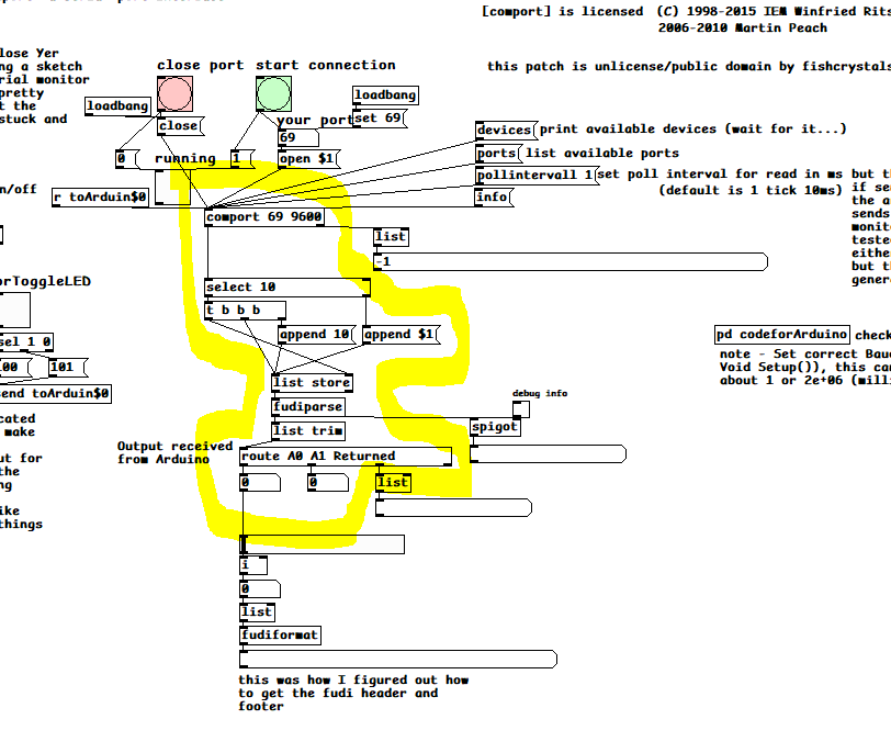 the other stuff was an early attempt at sending info to the arduino which hasnt been worked out and debug stuff I used to figure out how fudi talks.
there's been other ways to do this (like by https://drymonitis.me/code/ ..
and
)so this was just what worked for me.. here's the sketch comPortFixin.pd AnalogReadSerial2PureDataFUDI.ino
 posted in technical issues
Failure(1168) Error Message, Arduino to Pure Data
Hi, I'm trying to connect 8 sensors from an Arduino to output sound through Pure Data. I am struggling to get Pure Data to read the port. When trying to connect to the port using [comport], I get the error message "failure(1168)."
Max has worked fine for me in the past, and I double checked the port in the Arduino IDE. It works fine in the Arduino IDE serial monitor. I also close the Arduino IDE serial monitor (and application) before trying to connect to Pure Data, and I still get the same error message.
If it matters, the port I'm using was made with a Bluetooth module (HC-05) connected to my Arduino.
 posted in I/O hardware diy
Connecting and Unpacking or Routing from Arduino uno
You might want to give [serial_print] abstraction a try, I made it especially for communicating with Arduino's Serial.print() function. Your Arduino code seems alright for this case. You can find the abstraction here.
Connect [comport] to [serial_print], and both outlets of [serial_print] to [s ] ([send]) without arguments, like this:
[comport 1 9600]
|
[serial_print]
|           /
|         /
|       /
|      /
[send]
Then use [r ] ([recieve]) objects with the same argument as the string you use in your Arduino code, for example [r p], [r s1], [r f1], [r f2] for your first Arduino sketch, and [r a1] etc. [r dist] for your second sketch.
 posted in technical issues
Connecting and Unpacking or Routing from Arduino uno
* Hi everyone
I have searched around, I found any solutions that match my problem or are up-to-date unfortunately.
I’m having trouble unpacking and/Or routing the data coming in from sensors attached to my Arduino uno. The senses are working fine when I check the Arduino serial monitor before I began looking at the PD patch.
I just can’t seem to get them to unpack, or route in PD 0.5
Just wondering if anyone else has solved this - or has found this to be a problem?
Attached are images of two separate Arduino Scripps I’ve tried. One to try unpacking, the other to try routing - Plus, an image of my pure data patch to try testing the incoming signal data.
 [sAp-Sensors Input Test.pd](/uploads/files/1729806028183-sap-sensors-input-test.pd) 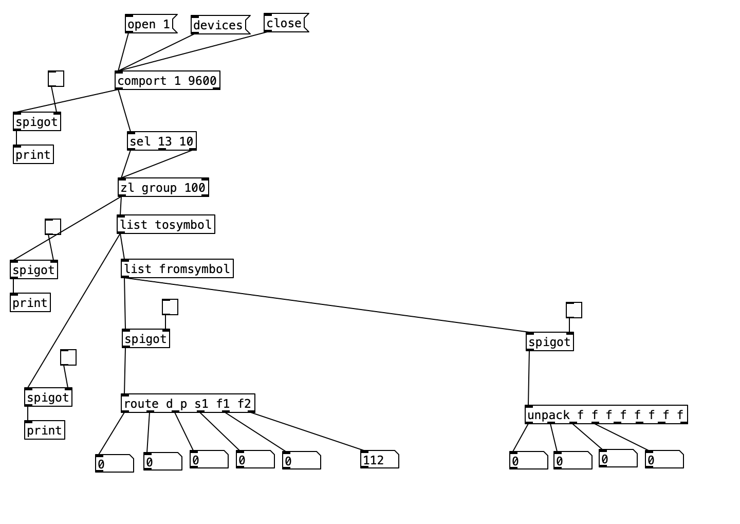 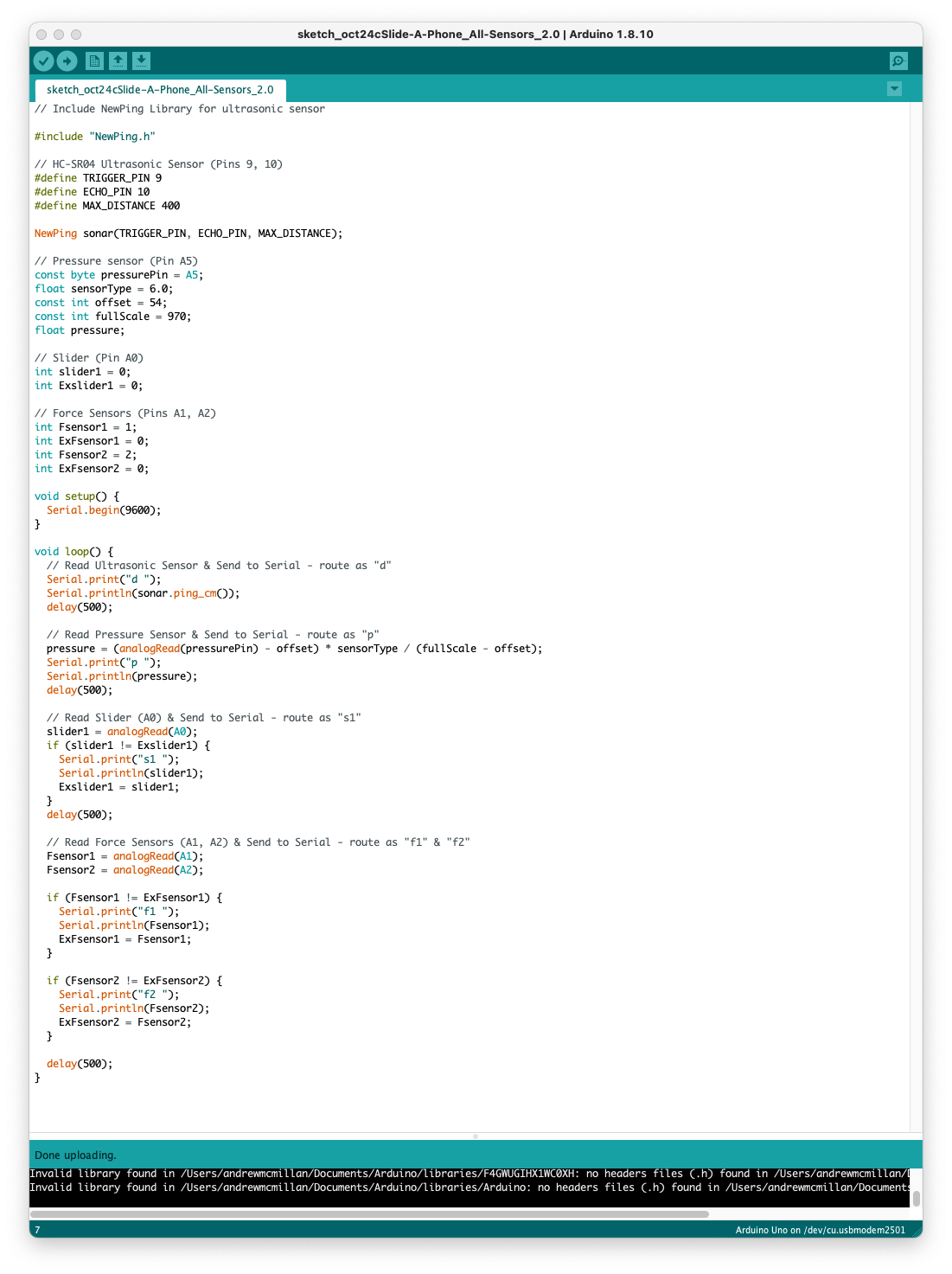
 posted in technical issues
Pi GPIO-pin serial communication with [comport]
Hi,
this is possible, I've been fiddling around with code and patch in this direction for some weeks now, starting with a Teensy LC and heavily leaning on excellent @alexandros Drymonitis tutorial "Arduino for Pd'ers". Sadly I damaged the Teensy (floating power supply wires - stupid me), and had to keep going using an Arduino Micro as a mere substitute (and a 5V-3V3 converter in between them), but I do remember that it was already working with the Teensy, sending values sampled from a potentiometer tied to A0 pin to a pd patch running on the Rpi.
As of now I am able to transmit in both directions, with various packet lengths depending of the type of data and as many "fluxes" as needed. My code and patch is by no means clean nor properly commented and I plan to share it in the future through GitHub. I could share this in a private way anyway, I just need a free evening to gather the bits and write some explanation lines.
In the meanwhile here are some tech points that come to my mind: (sorry this is rather "trivial", but in my experience such "trivial" topics can be time-consuming, sometimes)
-
connect Rx from one board to Tx of the other and GND together
-
use Serial1 (or higher indexes) for UART communication, Serial for common console debugging, as advised by the manufacturer PJRC
-
on linux I usually execute the command
sudo systemctl stop ModemManagerin a terminal first thing, if I remember well I had to find this workaround because the card couldn't be detected in Arduino IDE. (more of an Arduino Micro specific issue I guess but who knows...) -
sending data from the Teensy to the Rpi is easier (codewise) because you only have to create "packets" (i.e.: use start and end marker bytes to "frame" the relevant data) and send all at once. In the other way round (RPi->Teensy) you have to poll incoming data using a code structure that takes into account the fact that even with a high UART bitrate the Teensy will loop a great number of times, doing nothing, between incoming bytes because of its much higher clock frequency. See serial input basics - updated on arduino forums for more on that
Hope this will be useful, I'll try to pack up a decent recent version of my code and patch in order to share it soon.
Nau
 posted in technical issues
Pd compiled for double-precision floats and Windows
@jameslo said:
@ddw_music I love that story but am scratching my head over the 1/10 example you gave. Here's a test I made in Arduino c++: ... I went out 40 digits and didn't see anything unexpected. Was that example you gave just a metaphor for the issue, or is my test naive?
Not a metaphor at all:
[16, 17, 40].do { |prec|
    "% digits: %\n".postf(
        prec,
        0.1.asStringPrec(prec)
    )
};

16 digits: 0.1
17 digits: 0.10000000000000001
40 digits: 0.1000000000000000055511151231257827021182
As for Arduino, the float datatype reference says "Unlike other platforms, where you can get more precision by using a double (e.g. up to 15 digits), on the Arduino, double is the same size as float" -- so my guess here is that Serial places a limit on the number of digits it will try to render, and then fills the rest with zeros.
I went out 40 digits and didn't see anything unexpected.
Seeing zeros all the way out to 40 digits is unexpected! Arduino's output here is more comforting to end-users (which might be why they did that), but it isn't accurate.
Considering that Arduino calculates "double" using single precision, the output should deviate from the mathematically true value even earlier:
// 0.1.as32Bits = single precision but as an integer
// Float.from32Bits = double precision but based on the 32 bit float
Float.from32Bits(0.1.as32Bits).asStringPrec(40)

-> 0.100000001490116119384765625
The most reasonable conclusion I can draw is that Arduino is gussying up the output to reduce the number of "what the xxx is it printing" questions on their forum. That should not be taken as a standard against which other software libraries may be judged.
Edit: hmm, but here's Pd64.
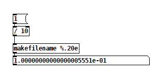
Pd64 is doing it right, and Arduino is not.
Getting back to how Pd seems to differ from other programming languages, I'm going to hazard a guess and say that Pd hasn't separated the value of a float from its display/storage format.
The value must be stored in standard single/double precision format. You need the CPU to be able to take advantage of floating point instructions.
It's rather that Pd has to render the arguments as text, and this part isn't syncing up with the "double" compiler switch.
PS I hope my attempt at humor didn't discourage @porres from responding to @oid's question. I'm sure he would have something more meaningful to contribute.
Of patchers as programming languages... well, I got a lot of opinions about that. Another time. For now, just to say, classical algorithms are much harder to express in patchers because patchers are missing a few key features of programming languages.
hjh
 posted in technical issues
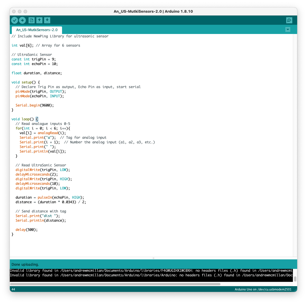
Ultrasonic distance sensors with Pd in Bela
The ultrasonic distance sensors are usually digital, not analog. If this is the case, you're trying to read a digital signal as analog, which doesn't make much sense. This sensor has two pins, a trigger and an echo. You have to send a high voltage to the trigger pin, then pull it low, and read the echo pin which will help you compute the distance based on the time it took for this trigger pulse to arrive back at the echo pin.
The code below (copied from Arduino'g Project Hub), uses Arduino's pulseIn() function, to compute the distance:
// Define Trig and Echo pin:
#define trigPin 2
#define echoPin 3
//  Define variables:
long duration;
int distance;
void setup() {
  // Define  inputs and outputs:
  pinMode(trigPin, OUTPUT);
  pinMode(echoPin, INPUT);
  //Begin Serial communication at a baudrate of 9600:
  Serial.begin(9600);
}
void  loop() {
  digitalWrite(trigPin, LOW);
  delayMicroseconds(5);
  digitalWrite(trigPin,  HIGH);
  delayMicroseconds(10);
  digitalWrite(trigPin, LOW);
  // Read  the echoPin, pulseIn() returns the duration (length of the pulse) in microseconds:
  duration = pulseIn(echoPin, HIGH);
  // Calculate the distance:
  distance=  duration*0.034/2;
  // Print the distance on the Serial Monitor
  Serial.print("Distance  = ");
  Serial.print(distance);
  Serial.println(" cm");
  delay(1000);
}
I searched online and found the source of this pulseIn() function in Arduino's forum, which is this:
/*
  wiring_pulse.c - pulseIn() function
  Part of Arduino - http://www.arduino.cc/

  Copyright (c) 2005-2006 David A. Mellis

  This library is free software; you can redistribute it and/or
  modify it under the terms of the GNU Lesser General Public
  License as published by the Free Software Foundation; either
  version 2.1 of the License, or (at your option) any later version.

  This library is distributed in the hope that it will be useful,
  but WITHOUT ANY WARRANTY; without even the implied warranty of
  MERCHANTABILITY or FITNESS FOR A PARTICULAR PURPOSE.  See the GNU
  Lesser General Public License for more details.

  You should have received a copy of the GNU Lesser General
  Public License along with this library; if not, write to the
  Free Software Foundation, Inc., 59 Temple Place, Suite 330,
  Boston, MA  02111-1307  USA

  $Id: wiring.c 248 2007-02-03 15:36:30Z mellis $
*/

#include "wiring_private.h"
#include "pins_arduino.h"

/* Measures the length (in microseconds) of a pulse on the pin; state is HIGH
 * or LOW, the type of pulse to measure.  Works on pulses from 2-3 microseconds
 * to 3 minutes in length, but must be called at least a few dozen microseconds
 * before the start of the pulse. */
unsigned long pulseIn(uint8_t pin, uint8_t state, unsigned long timeout)
{
    // cache the port and bit of the pin in order to speed up the
    // pulse width measuring loop and achieve finer resolution.  calling
    // digitalRead() instead yields much coarser resolution.
    uint8_t bit = digitalPinToBitMask(pin);
    uint8_t port = digitalPinToPort(pin);
    uint8_t stateMask = (state ? bit : 0);
    unsigned long width = 0; // keep initialization out of time critical area

    // convert the timeout from microseconds to a number of times through
    // the initial loop; it takes 16 clock cycles per iteration.
    unsigned long numloops = 0;
    unsigned long maxloops = microsecondsToClockCycles(timeout) / 16;

    // wait for any previous pulse to end
    while ((*portInputRegister(port) & bit) == stateMask)
        if (numloops++ == maxloops)
            return 0;

    // wait for the pulse to start
    while ((*portInputRegister(port) & bit) != stateMask)
        if (numloops++ == maxloops)
            return 0;

    // wait for the pulse to stop
    while ((*portInputRegister(port) & bit) == stateMask) {
        if (numloops++ == maxloops)
            return 0;
        width++;
    }

    // convert the reading to microseconds. The loop has been determined
    // to be 20 clock cycles long and have about 16 clocks between the edge
    // and the start of the loop. There will be some error introduced by
    // the interrupt handlers.
    return clockCyclesToMicroseconds(width * 21 + 16);
}
This is already getting complicated, as pulseIn() uses other functions which should be found and translated to Pd. I guess the best thing you can do is try to translate the first code chuck in this reply to Pd, and when you read a high voltage in the echo pin, do some math to calculate the distance.
In essence, set a digital input and a digital output pin on the Bela, trigger the output pin with a high and low signal, and keep reading the input pin (you should probably use a pull-down resistor there), until you get a high. Calculate the time it took with the [timer] object and do some simple math to get the distance. Do that with distances you know first, and then use the rule of three based on the known distance and the time you get. At least, that's how I would try to get this to work.
Another solution is to use an infrared proximity sensor, which is analog, and it's probably much easier to use. But this gets the proximity of obstacles right in front of it only, while the ultrasonic range finder has a wider field where it can detect obstacles.
posted in technical issues
comport (couldn't create / can't load abstraction within itself)
Hello all,
Looking for some help with the comport object, it has suddenly stopped working.
When I try to create the object I get the error:
comport
... couldn't create
comport: can't load abstraction within itself
I have updated PD, deleted comport within the externals, then reinstalled it using help>find externals within PD and still get the same error - any ideas? I have also tried using "declare" to no effect.
When I open the "comport-help.pd", "comport-meta.pd" and "comport-stress-test" within the externals>comport folder all comport objects are greyed out... Trying to get PD to talk with Arduino... Thanks!
 posted in technical issues