Polyrytm , dividing master metro
I am having some issues here with automating the tempo of second metro (denominator )
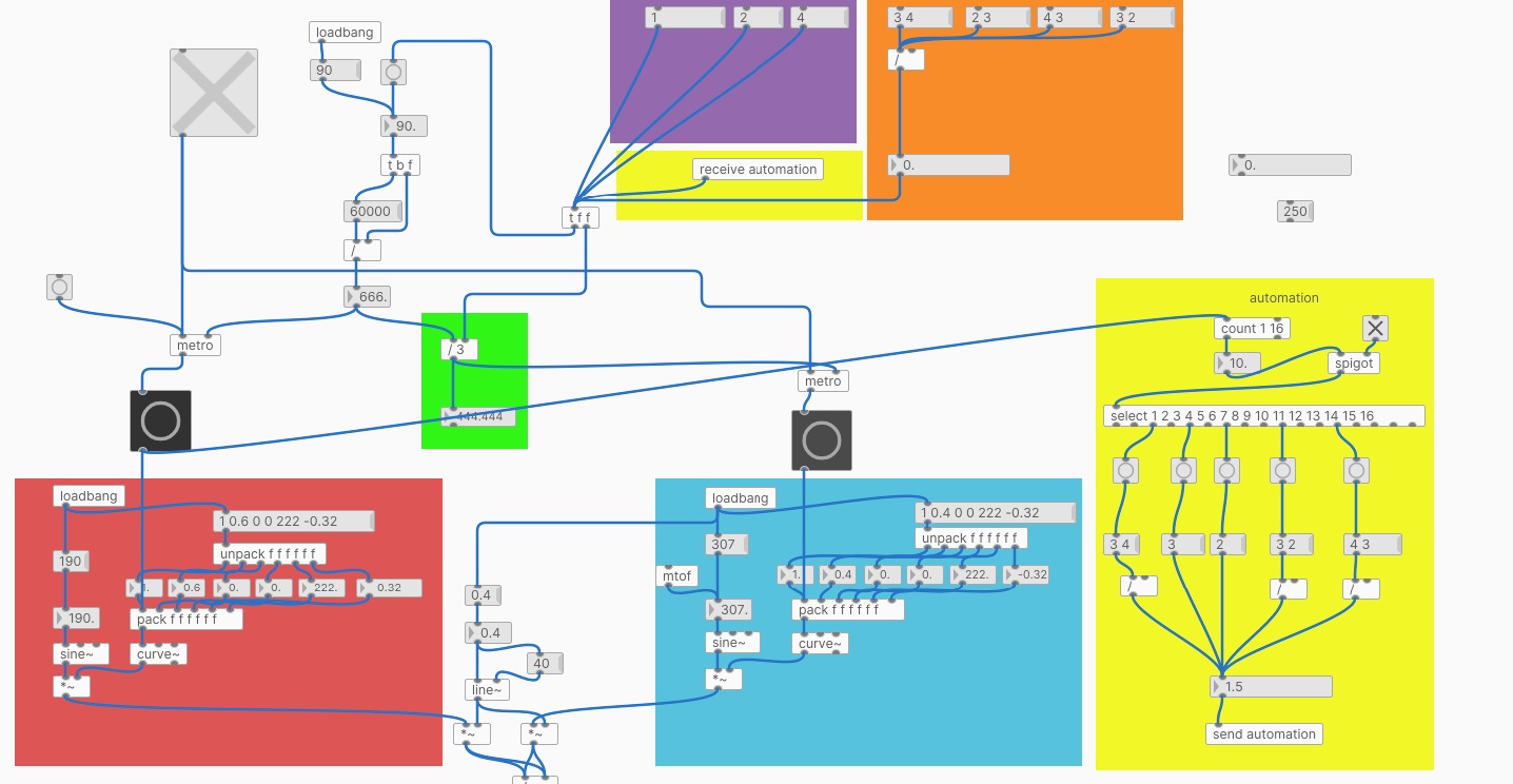
The structure is pretty simple
There are 2 metro objects , a red and a blue one
The red one (bottom left corner and left channel ) is triggering a sine , the blue metro is triggering another sine ( bottom right right channel).
Both are using a curve envelope ( cyclone )
The master tempo is located at the top , default is 90 bpm
This goes into a tbf , the float is first send to he right inlet of a division , then the bang is triggering a message of 60000 ms
The result is the time of a beat (one minute divided by BPM) .
It all works fine when disabling-enabling mast toggle but that's not what I want.
Now the issue , the purple and orange boxes all house different denomitor values , used to calculate the new tempo for the second metro ( blue right channel )
When manually triggered these go into a tff , the right outlet of tff goes into a division modue ( green box) and the left output
is trigerring a bang to redo the calculation .
As some of you have guessed , when doing this realtime the second metro is losing sync because of the recalculation .
I tried to automate this ( yellow box, enable spigot ) by sending a bang from the master RED metro into a count-selet module , the ouput is triggering new
denominator values that is send to the tff module (using send receive boxes ) , but again Blue metro is not starting on sync .
Anyone help is appreciated to keep blue metro on sync when receiving a new value .
 posted in technical issues
PlugData / Camomile "position" messages: What are these numbers?
@whale-av said:
@ddw_music Yes.... buffer.
Maybe some DAWs have implemented a tempo message since then?
Tempo must be available, since plug-ins have been doing e.g. tempo-synced delays for at least a decade already.
(In fact, it is available via Camomile: [route tempo position].)
Anyway... I've been considering solutions, and I think I can do this.
- Set some threshold close to the beat, but before the beat, say x.9 beats.
- For the first tick past the threshold, get "time to next beat" = roundUp(pos) - pos = int(pos + 0.99999999) - pos.
- [delay] by this many beats ([delay] and the tick-scheduler will have been fed "tempo x permin" messages all along).
- Then issue the tick message to the scheduler, in terms of whole beats (where the time-slice duration is always 1.0).
At constant tempo, I'd expect this to be sub-ms accurate.
If the tempo is changing, especially a large, sudden change, then there might be some overlaps or gaps. But [delay] correctly handles mid-delay tempo changes, so I'd expect these to be extremely small, probably undetectable to the ear.
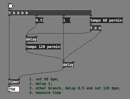
Half a beat at 60 bpm + half a beat at 120 bpm does indeed = 750 ms -- so the delay object is definitively updating tempo in the middle of a wait period.
I'll have to build it out and I don't have time right now, but I don't see an obvious downside.
hjh
 posted in technical issues
PlugData / Camomile "position" messages: What are these numbers?
@ddw_music said:
To work with the scheduler, I need to be able to anticipate the next tick time. The difference between successive beats (first number) appears to be consistently 0.04644012, and this seems to be proportional to tempo (160 bpm gets 0.061919212341).
Different machine, different DAW, I get half that (0.02322). So I guess this is a number of beats (because it increments by a larger amount at higher tempo = more beats per unit of time) and it must be updating once per audio callback, and the soundcards must be configured differently.
It's tricky: you can't just tick beats because you never get an exact whole beat (unlike abl_link~ which does provide a "step" output), and the beat interval between successive "playhead" ticks may change, and you won't detect that change until after you've already ticked the current one. So there will always be some sync inaccuracy AFAICS, probably minimal at constant tempo.
I guess nobody cares much about interoperability but I feel like I'm this close to a good way...
hjh
posted in technical issues
Having lots of switches into Pd
@alexandros said:
Have you detected whether the crash happens with
else if (in == 'd')orelse if (in == 'p')?
It happens only in else if (in == 'p'). When I bypass that I can update snapshot~ by 1 ms (I assume that 'c' will still be sent by 1 ms intervals).
In the Pd patch it's probably better to swap the $1 and $2 values in the messages. Have the channel set in a cold inlet and the value in a hot one and then write this message
print $2c$1v
Ok I did that.
I see in the screenshot of the patch that the PWM message is not connected to [comport]. Is this for some particular reason?
It is to make sure Pd does not crash/freeze until I want to try the code.
Maybe the 10ms interval for sending a PWM value to [comport] is a bit too fast. Did you try something slower, like 50ms?
That made it work. If I use six pwm pins the limit is 150 ms before crash.
Question 1: Could there something bad that happens around else if (in == 'p')? In another code snippet you used this format:
  while(Serial.available()){
    byte inByte = Serial.read();
    if((inByte >= '0') && (inByte <= '9'))
    temporary = 10 * temporary + inByte - '0';
    else{
      if(inByte == 'p'){
        pwmLEDvalue = temporary;
        temporary = 0;
      }
      else if(inByte == 'd'){
        dspLEDstate = temporary;
        temporary = 0;
      }
    }
    analogWrite(pwmLED, pwmLEDvalue);
    digitalWrite(dspLED, dspLEDstate);
  }
compared to this in the current sketch:
if (Serial.available()) {

    static int temp;
    byte in = Serial.read();

    if (isDigit(in)) temp = temp * 10 + in - '0';

    else if (in == 'c') {
      channel = temp;
      temp = 0;
    }

    else if (in == 'd') {
      digitalWrite(outPins[channel], temp);
      temp = 0;
    }

    else if (in == 'p') {
      analogWrite(pwmPins[channel], temp);
      temp = 0;
    }

  }
Question 2: Is this crash of Pd and the computer (macOS Mojave) expected behavior in a situation like this? If it is not, maybe it should be reported as a bug. It happens consistently.
Thoughts: Could there be a problem in [comport]? This crash behavior is identical with the problems I had when using Pdunio/Firmata.
 posted in I/O hardware diy
Having lots of switches into Pd
@alexandros said:
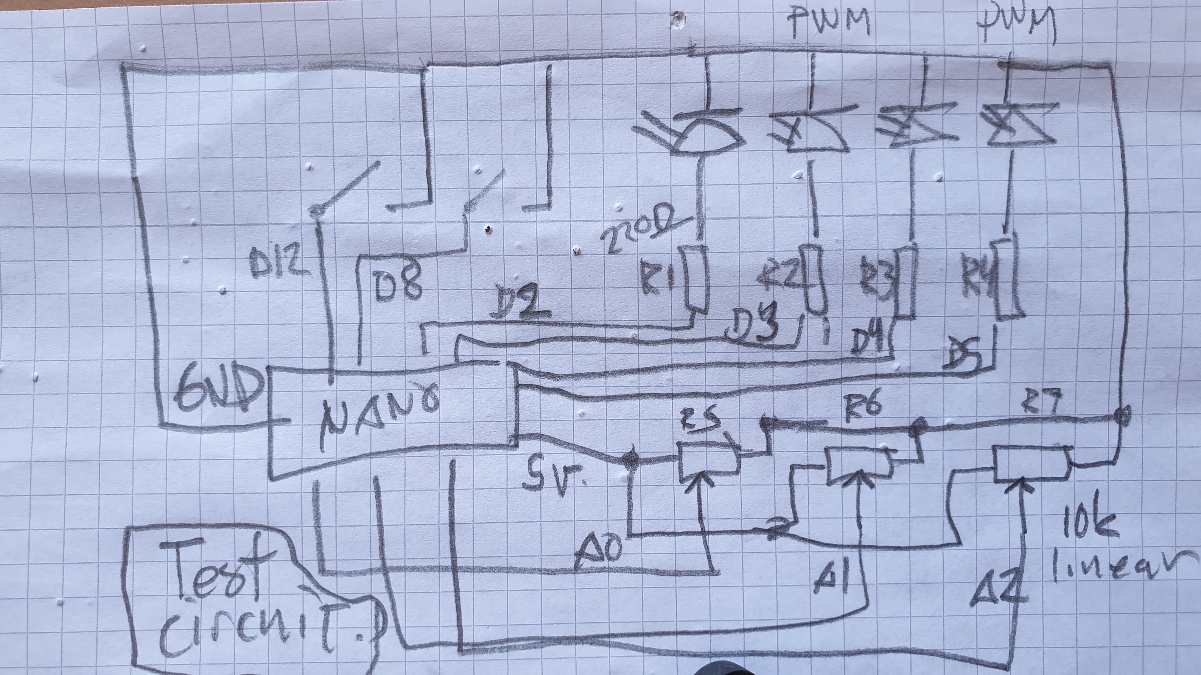
@cfry the thing is that the last bit of code you posted seems just fine, excluding the calling to pinMode where you're enabling the integrated pull-up resistors. Can you try that code removing these lines in setup(), and instead of heat sensitive sensors or whatever you're currently using, use simple potentiometers and verify whether that works or not? In case it doesn't work, please post a diagram of your circuit in some way (even hand-drawn is ok), as well as the full Arduino sketch and a screenshot of the Pd patch.
int outPins[3] = {2, 4, 7};
int pwmPins[6] = {3, 5, 6, 9, 10, 11};

int channel = 0;

int inPins[2] = {8, 12};
int analogPins[8] = {0, 1, 2, 3, 4, 5, 6, 7};

// int debug_skip = 0;

void setup() {

   for (int i = 0; i < 3; i++) {
    pinMode(outPins[i], OUTPUT);
  }
    for (int i = 0; i < 6; i++) {
    pinMode(pwmPins[i], OUTPUT);
  }
    for(int i = 0; i < 2; i++) {
    pinMode(inPins[i], INPUT_PULLUP);
  }

  Serial.begin(115200);

}

void loop() {

//DO OUTPUTS

  if (Serial.available()) {

    static int temp;
    byte in = Serial.read();

    if (isDigit(in)) temp = temp * 10 + in - '0';

    //quote out this section to avoid crash

    else if (in == 'c') {
      channel = temp;
      temp = 0;
    }

    else if (in == 'd') {
      digitalWrite(outPins[channel], temp);
      temp = 0;
    }

    else if (in == 'p') {
      analogWrite(pwmPins[channel], temp);
      temp = 0;
    }

    //end quote out here

  }

// DO INPUTS

Serial.print("analog");

  for(int i = 0; i < 8; i++){

    unsigned int analogVal = analogRead (analogPins[i]);

    Serial.print(" ");
    Serial.print(analogVal);
  }

  Serial.println();

  Serial.print("digital");

  for(int i = 0; i < 2; i++) {

    unsigned int digitalVal = digitalRead(inPins[i]);

    Serial.print(" ");
    Serial.print(digitalVal);
  }

  Serial.println();

}
If I do the following PureData will always freeze and requires force quit. Occasionally the whole OS becomes sluggish/freeze and need a reboot.
- Have this code snippet in the Arduino sketch
    //quote out this section to avoid crash

    else if (in == 'c') {
      channel = temp;
      temp = 0;
    }

    else if (in == 'd') {
      digitalWrite(outPins[channel], temp);
      temp = 0;
    }

    else if (in == 'p') {
      analogWrite(pwmPins[channel], temp);
      temp = 0;
    }

    //end quote out here
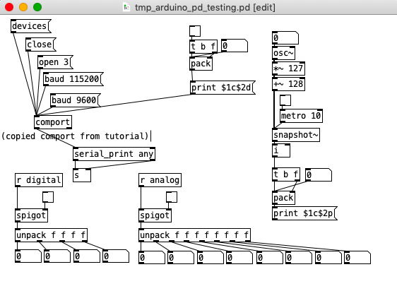
- Connect [print $1c$2p] -> [comport]
(I have also noted different behavior using [comport] from the tutorial by copy and paste compared to creating a comport object (cmd+1 and then typing). At times the latter did not work at all, but after reboot of the system both seems to work.)
Thanks for helping
Here is the patch from screenshot above:
tmp_arduino_pd_testing.pd
posted in I/O hardware diy
BPM tempo wavering
Hi Everyone,
In the last year I have recorded a few tracks using Pure Data and I am exporting them into Logic to mix them. I notice that the BPM tempo wavers. For example, if I have a tempo of 150 bpm, when I export the tracks to Logic it might have a tempo of 149.82 for a few bars, then 149.91, then 149.81, etc. it always goes a little slower in a seemingly random way. Over the course of a large number of measure it is way off the tempo. I know this because I have a kick drum pattern that always attacks on a certain beat and I can see it’s off.
I have heard a few other people mention this issue, but it has never really been an issue for me until now. Does anyone have any strategies for dealing with this? I am sequencing a few elements and I want them all to be in sync, drums, a bass part, etc. And all the various drums themselves, like a kick drum, snare drum, hi hat, etc.
I am using regular metro objects all starting from a single message that is sent to the different metronomes. Should I try and use all audio rate timing or something similar?
It is not easy to notice the tempo wavering by listening, but sometimes I think I can notice it too, and it’s sort of weird rhythmic feel as well.
Thank you in advance for any advice.
 posted in technical issues
Having lots of switches into Pd
@alexandros now pwm and digital output work fine, but when I try to merge with digital and analog inputs it goes wrong. the leds flicker randomly. If you remove the code below
// do input pins: flicker stops. :/
int outPins[3] = {2, 4, 7};

int pwmPins[6] = {3, 5, 6, 9, 10, 11};

// a global variable to hold which LED we want to control (either digital or PWM)
int channel = 0;

int inPins[2] = {12, 13};

int analogPins[8] = {0, 1, 2, 3, 4, 5, 6, 7};

void setup() {

   for (int i = 0; i < 3; i++) {
    pinMode(outPins[i], OUTPUT);
  }
    for (int i = 0; i < 6; i++) {
    pinMode(pwmPins[i], OUTPUT);
  }
    for(int i = 0; i < 2; i++) {
    pinMode(inPins[i], INPUT);
  }

  pinMode(A0, INPUT_PULLUP);
  pinMode(A1, INPUT_PULLUP);
  pinMode(A2, INPUT_PULLUP);
  pinMode(A3, INPUT_PULLUP);
  pinMode(A4, INPUT_PULLUP);
  pinMode(A5, INPUT_PULLUP);
  pinMode(A6, INPUT);
  pinMode(A7, INPUT);

//DEFAULT works with thermistors,
//INTERNAL with transitor thermostats
  analogReference(DEFAULT);

  Serial.begin(115200);

}

void loop() {

  //do output pins:

  if (Serial.available()) {
    static int temp;
    byte in = Serial.read();
    if (isDigit(in)) temp = temp * 10 + in - '0';
    else if (in == 'c') {
      channel = temp;
      temp = 0;
    }
    else if (in == 'd') {
      digitalWrite(outPins[channel], temp);
      temp = 0;
    }
    else if (in == 'p') {
      analogWrite(pwmPins[channel], temp);
      temp = 0;
    }
  }

  // do input pins:

Serial.print("analog"); // use "knobs" as a keyword so you can receive
  // the knob values as a list with a [r analog] in Pd
  for(int i = 0; i < 8; i++){
    unsigned int analogVal = analogRead (analogPins[i]);
    Serial.print(" "); // first print a white space to separate the "knob" keyword from the values
    // and the values from each other
    Serial.print(analogVal); // then  print the actual knob value
  }
  Serial.println(); // finally print a newline character to denote end of data for keyword "knobs"

  Serial.print("digital");
  for(int i = 0; i < 2; i++) {
    unsigned int digitalVal = digitalRead(inPins[i]);
    Serial.print(" ");
    Serial.print(digitalVal);
  }
  Serial.println();
}
Just got my MIDI Violin! Here are some notes on it and how to use it with PD
@whale-av Hey, sorry I never replied- I just saw your reply now after I bought the instrument.  I ended up getting the BOSS GP-10 as a MIDI interface for the instrument. I knew the GR-55, SY-300 and SY-1000 would work as well, but didn't know about the GI-20. Maybe it would've been more affordable...
Here are my notes. Happy to hear anyone else's experiences or ideas about how I can get the most out of this device:
1)The instrument has screws on the back that you can turn to increase/decrease the sensitivity of each string. I've adjusted these a bit with dealing with the problems mentioned below in observation 9)
2)The GP-10 also has some settings for more or less dynamic contrast. I've experimented with setting these differently, though setting "Dynamics" to 1 and "Play Feel" to FEEL 1 seems to be the best. Changing these doesn't seem to do anything for the problem in 9).
3)I have the GP-10 set to MONO mode, rather than poly mode so that each string outputs to a separate MIDI channel.
-
The output to separate channels works well if you do clear attacks with the bow (or use pizzicato of course). The attacks need to be clear whenever you switch to a different string. Raising the sensitivity (cf. 5)) allows you to have clear attacks that are still somewhat quiet.
-
As long as a note is sustained, you get continuously updated bend values, which can be combined with the original noteOn value to get exact pitches and perform glissandi. I combine the two values in Pure Data with math objects. noteplusbend.pd
-
The MIDI velocity value does not update continuously, but in PD I can use the velocity's value as a switch to allow the Audio-in (which also comes in through the GP-10's USB) to control the volume of the MIDI-activated note via [spigot].
-
Because attacks with the bow need to be clear, if you fade in a note very gradually with the bow, it won't be detected as MIDI.
-
By combining 6) and 7) I can construct patches in Pure Data so that a certain sound will play and be controlled purely by the Audio-input and that others will be activated by MIDI+Audio-Input. Eg. I can fade in a sound, crescendo with an up-bow and then attack crisply on the down-bow to activate other sounds.
-
There are some issues with stable pitch detection when playing double-stops (diads) on two neighboring strings. It seems when doing so that there's some interference. However, for some reason, playing smaller intervals (major 3rds or lower) seems to work better than larger intervals. And avoiding open strings helps as well.
-
The pitch detection of 9) could be ameliorated by removing the bend value from the equation, but of course glissandi/microtonality would be lost as a result.
-
The E string (the highest one) gives the quietest, least consistent output. Pitch detection suddenly falls off after the first octave.
 posted in I/O hardware diy
Having lots of switches into Pd
First of all, don't separate functions for reading the serial data, even if you want to read data for different kinds of stuff.
Combining digital with PWM pins should be sort of straight forward. Here's some example code:
int digitalPins[4] = {2, 4, 7, 10};
// use an array for all the pins of similar type, e.g. PWM pins, like below
int pwmPins[6] = {3, 5, 6, 9, 11, 12}; // can't remember the exact pin numbers with PWM, change accordingly

// a global variable to hold which LED we want to control (either digital or PWM)
int channel = 0;

void setup() {
  for (int i = 0; i < 4; i++) {
    pinMode(digitalPins[i], OUTPUT);
    pinMode(pwmPins[i], OUTPUT);
  Serial.begin(115200);
}

void loop() {
  if (Serial.available()) {
    static int temp;
    byte in = Serial.read();
    if (isDigit(in)) temp = temp * 10 + in - '0';
    else if (in == 'c') {
      channel = temp;
      temp = 0;
    }
    else if (in == 'd') {
      digitalWrite(digitalPins[channel], temp);
      temp = 0;
    }
    else if (in == 'a') {
      analogWrite(pwmPins[channel], temp);
      temp = 0;
    }
}
Check this code with Pd by sending messages of the type print $1c$2d for digital values and print $1c$2a for analog values. $1 is the led number (incrementing, starting from 0), and $2 is the value you want to write, 0-1 for digital and 0-255 for PWM.
 posted in I/O hardware diy
Having lots of switches into Pd
@alexandros
This code sort of works with wip_multiple_PWM.pd
// merging works but pwm leds are choppy.

// number of elements in arrays need to
// match for() cycles in void setup and void loop
int pinsIn[2] = {2, 4};
int pinsAnalog[8] = {0, 1, 2, 3, 4, 5, 6, 7};

int pin = 0;
int val = 0;
int pinsOut[2] = {7, 12};

//TMP setup pwm:

// variables to hold pin numbers
int pwmLED1 = 3;
int pwmLED2 = 5;
int pwmLED3 = 6;
int pwmLED4 = 9;
int pwmLED5 = 10;
int pwmLED6 = 11;

// variables to hold pin states
int pwmLEDvalue1;
int pwmLEDvalue2;
int pwmLEDvalue3;
int pwmLEDvalue4;
int pwmLEDvalue5;
int pwmLEDvalue6;

//should this be omitted and use the a
// variable to hold and assemble incoming data
int temporary;

//END TMP pwm setup

void setup()
{
  //set up a total of pins for digital input (has to match number of elements in array)
  for(int i = 0; i < 2; i++)
  pinMode(pinsIn[i], INPUT);

  for (int i = 0; i < 2; i++) {
    pinMode(pinsOut[i], OUTPUT);
    digitalWrite(pinsOut[i], LOW);
  }

//DEFAULT works with thermistors,
//INTERNAL with transitor thermostats

  analogReference(DEFAULT);

  pinMode(A0, INPUT_PULLUP);
  pinMode(A1, INPUT_PULLUP);
  pinMode(A2, INPUT_PULLUP);
  pinMode(A3, INPUT_PULLUP);
  pinMode(A4, INPUT_PULLUP);
  pinMode(A5, INPUT_PULLUP);
  pinMode(A6, INPUT);
  pinMode(A7, INPUT);

//TMP test pwm setup:

  pinMode(pwmLED1, OUTPUT);
  pinMode(pwmLED2, OUTPUT);
  pinMode(pwmLED3, OUTPUT);
  pinMode(pwmLED4, OUTPUT);
  pinMode(pwmLED5, OUTPUT);
  pinMode(pwmLED6, OUTPUT);

  Serial.begin(115200); // perhaps use a faster baud rate
}

void loop()
{
  Serial.print("knobs"); // use "knobs" as a keyword so you can receive
  // the knob values as a list with a [r knobs] in Pd
  for(int i = 0; i < 8; i++){
    unsigned int knob = analogRead (pinsAnalog[i]);
    Serial.print(" "); // first print a white space to separate the "knob" keyword from the values
    // and the values from each other
    Serial.print(knob); // then  print the actual knob value
  }
  Serial.println(); // finally print a newline character to denote end of data for keyword "knobs"

  // the same technique applies to the switches too
  // receive the switch values as a list with [r switches]
  Serial.print("switches");
  for(int i = 0; i < 2; i++) {
    int switchVal = digitalRead(pinsIn[i]);
    Serial.print(" ");
    Serial.print(switchVal);
  }
  Serial.println();

  //handle digital outputs
  if (Serial.available()) {
    static int temp;
    byte in = Serial.read();
    if (isDigit(in)) {
      temp = temp * 10 + in - '0';
    }
    else if (in == 'p') {
      pin = temp;
      temp = 0;
    }
    else if (in == 'v')  {
      val = temp;
      temp = 0;
      digitalWrite(pinsOut[pin], val);
    }
}

//TMP merge test PWMs:
while(Serial.available()){
     byte inByte = Serial.read();
     if((inByte >= '0') && (inByte <= '9'))
       temporary = 10 * temporary + inByte - '0';
     else{
       if(inByte == 'p'){
         pwmLEDvalue1 = temporary;
         temporary = 0;
       }
       else if(inByte == 'q'){
         pwmLEDvalue2 = temporary;
         temporary = 0;
       }
       else if(inByte == 'r'){
         pwmLEDvalue3 = temporary;
         temporary = 0;
       }
       else if(inByte == 's'){
         pwmLEDvalue4 = temporary;
         temporary = 0;
       }
       else if(inByte == 't'){
         pwmLEDvalue5 = temporary;
         temporary = 0;
       }
       else if(inByte == 'u'){
         pwmLEDvalue6 = temporary;
         temporary = 0;
       }
     }
     analogWrite(pwmLED1, pwmLEDvalue1);
     analogWrite(pwmLED2, pwmLEDvalue2);
     analogWrite(pwmLED3, pwmLEDvalue3);
     analogWrite(pwmLED4, pwmLEDvalue4);
     analogWrite(pwmLED5, pwmLEDvalue5);
     analogWrite(pwmLED6, pwmLEDvalue6);
     //digitalWrite(dspLED, dspLEDstate);
   }
}
This is the code without PWM control. It works fine.
//number of elements in arrays need to match for() cycles in void setup
int pinsIn[4] = {6, 7, 8, 9};
int pinsAnalog[8] = {0, 1, 2, 3, 4, 5, 6, 7};

int pin = 0;
int val = 0;
int pinsOut[4] = {2, 3, 4, 5};

void setup()
{
  //set up a total of pins for digital input (has to match number of elements in array)
  for(int i = 0; i < 4; i++)
  pinMode(pinsIn[i], INPUT);

  for (int i = 0; i < 4; i++) {
    pinMode(pinsOut[i], OUTPUT);
    digitalWrite(pinsOut[i], LOW);
  }
//DEFAULT works with thermistors,
//INTERNAL with transitor thermostats
// ELLER var det tvartom???
  analogReference(DEFAULT);

  pinMode(A0, INPUT_PULLUP);
  pinMode(A1, INPUT_PULLUP);
  pinMode(A2, INPUT_PULLUP);
  pinMode(A3, INPUT_PULLUP);
  pinMode(A4, INPUT_PULLUP);
  pinMode(A5, INPUT_PULLUP);
  pinMode(A6, INPUT);
  pinMode(A7, INPUT);

  Serial.begin(115200); // perhaps use a faster baud rate
}

void loop()
{
  Serial.print("knobs"); // use "knobs" as a keyword so you can receive
  // the knob values as a list with a [r knobs] in Pd
  for(int i = 0; i < 8; i++){
    unsigned int knob = analogRead (pinsAnalog[i]);
    Serial.print(" "); // first print a white space to separate the "knob" keyword from the values
    // and the values from each other
    Serial.print(knob); // then  print the actual knob value
  }
  Serial.println(); // finally print a newline character to denote end of data for keyword "knobs"

  // the same technique applies to the switches too
  // receive the switch values as a list with [r switches]
  Serial.print("switches");
  for(int i = 0; i < 4; i++) {
    int switchVal = digitalRead(pinsIn[i]);
    Serial.print(" ");
    Serial.print(switchVal);
  }
  Serial.println();

  //handle digital outputs
  if (Serial.available()) {
    static int temp;
    byte in = Serial.read();
    if (isDigit(in)) {
      temp = temp * 10 + in - '0';
    }
    else if (in == 'p') {
      pin = temp;
      temp = 0;
    }
    else if (in == 'v')  {
      val = temp;
      temp = 0;
      digitalWrite(pinsOut[pin], val);
    }
}
}
and here is the code from tutorial5 from Arduino for Pd'ers. It goes with arduinoforpdrs_tut5.pd
// variables to hold pin numbers
int pwmLED = 9;
int dspLED = 2;
// variables to hold pin states
int pwmLEDvalue;
int dspLEDstate;
//variable to hold and assemble incoming data
int temporary;

void setup()
{
  pinMode(pwmLED, OUTPUT);
  pinMode(dspLED, OUTPUT);
  Serial.begin(9600);
}

void loop()
{
  while(Serial.available()){
    byte inByte = Serial.read();
    if((inByte >= '0') && (inByte <= '9'))
    temporary = 10 * temporary + inByte - '0';
    else{
      if(inByte == 'p'){
        pwmLEDvalue = temporary;
        temporary = 0;
      }
      else if(inByte == 'd'){
        dspLEDstate = temporary;
        temporary = 0;
      }
    }
    analogWrite(pwmLED, pwmLEDvalue);
    digitalWrite(dspLED, dspLEDstate);
  }
}
I am aiming at using same type of array handling as for the digital outs.
Thanks a lot
posted in I/O hardware diy