Routing different signals to clone instances
Hello all!
I’m new to this forum! However I’ve been working with Pd for a while. Currently I’m programming a polyphonic synth in Pd with FM capabilities and I’m facing a problem. I have created some sort of a module which includes one oscillator, a low pass filter and an ADSR envelope generator. The output of this module is an audio signal. It also includes some inputs and one of them is a signal input for frequency modulation (it receives a signal from the outside and uses it to modulate the frequency of the oscillator inside the module). I use clone command to create multiple instances of the same module to make it polyphonic. Then I tried to route a signal from another cloned module to the FM input of the first module and the obvious ocurred: when I play only one note the FM works as supposed to. But when I play multiple notes it sounds terrible and it is because the audio signal of all the notes from the second module goes to the FM input of the first module and then it is routed to all the cloned instances of it. What I need is to route only the signal corresponding to one note and route it to the same note of the first module. Is there any way to achieve this? I understand that a signal goes equally to all instances of a cloned object, but is it possible get separate signals from all instances of the second module and route them separately to the corresponding instances for the first module?
 posted in technical issues
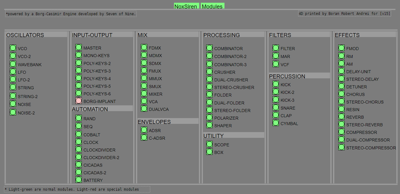
NoxSiren - Modular synthesizer system <- [v15]
NoxSiren is a modular synthesizer system where the punishment of failure is the beginning of a new invention.
--DOWNLOAD-- NoxSiren for :
-
Pure Data :
NoxSiren v15.rar
NoxSiren v14.rar -
Purr Data :
NoxSiren v15.rar
NoxSiren v14.rar
--DOWNLOAD-- ORCA for :
- x64, OSX, Linux :
https://hundredrabbits.itch.io/orca
In order to connect NoxSiren system to ORCA system you also need a virtual loopback MIDI-ports:
--DOWNLOAD-- loopMIDI for :
- Windows 7 up to Windows 10, 32 and 64 bit :
https://www.tobias-erichsen.de/software/loopmidi.html
#-= Cyber Notes [v15] =-#
- added BORG-IMPLANT module.
- introduction to special modules.
- more system testing.
#-= Special Modules [v15] =-#
- BORG-IMPLANT (connects ORCA MIDI system to NoxSiren system)
#-= Current Modules [v15] =-#
- VCO (voltage-controlled-oscillator)
- VCO2 (advance voltage-controlled-oscillator)
- WAVEBANK (additive synthesis oscillator)
- ADSR (Attack-Decay-Sustain-Release envelope)
- C-ADSR (Curved Attack-Decay-Sustain-Release envelope)
- CICADAS (128 steps-Euclidean rhythm generator)
- CICADAS-2 (advance 128-steps polymorphic-Euclidean rhythm generator)
- COMPRESSOR (lookahead mono compressor unit)
- DUAL-COMPRESSOR (2-channel lookahead mono compressor unit)
- STEREO-COMPRESSOR (lookahead stereo compressor unit)
- MONO-KEYS (virtual 1-voice monophonic MIDI keyboard)
- POLY-KEYS-2 (virtual 2-voice polyphonic MIDI keyboard)
- POLY-KEYS-3 (virtual 3-voice polyphonic MIDI keyboard)
- POLY-KEYS-4 (virtual 4-voice polyphonic MIDI keyboard)
- POLY-KEYS-5 (virtual 5-voice polyphonic MIDI keyboard)
- POLY-KEYS-6 (virtual 6-voice polyphonic MIDI keyboard)
- BATTERY (simple manual triggered machine for drumming.)
- REVERB (reverb unit with lowpass control)
- STEREO-REVERB (stereo reverb unit with lowpass control)
- RESIN (advanced rain effect/texture generator)
- NOISE (generates black,brown,red and orange noise)
- NOISE2 (generates yellow,blue,pink and white noise)
- COBALT (6-stage polyrhythm generator)
- SHAPER (basic shaper unit)
- FOLDER (basic wave folding unit)
- STEREO-FOLDER (stereo wave folding unit)
- DUAL-FOLDER (advance wave folding unit)
- POLARIZER (transform a signal into bi-polar, uni-polar, inverted or inverted uni-polar form)
- CLOCK (generates a BPM clock signal for sequencing other modules)
- CLOCKDIVIDER (a clock divider with even division of clock signal)
- CLOCKDIVIDER2 (a clock divider with odd division of clock signal)
- DELAY-UNIT (delay unit)
- STEREO-DELAY (stereo delay unit)
- CHORUS (chorus unit)
- STEREO-CHORUS (stereo chorus unit)
- SEQ (advance 16-step/trigger sequencer)
- KICK (synthesize kick unit)
- KICK2 (synthesize flavor of KICK module)
- KICK3 (synthesize flavor of KICK module)
- SNARE (synthesize snare unit)
- CLAP (synthesize clap unit)
- CYMBAL (synthesize cymbal unit)
- RAND (RNG generator for other modules parameters)
- FMOD (feedback modulation unit)
- AM (amplitude modulation unit)
- RM (ring modulation unit)
- LFO (low-frequency-oscillator)
- LFO2 (advance low-frequency-oscillator)
- COMBINATOR (combine two waves)
- COMBINATOR2 (combine three waves)
- COMBINATOR3 (combine four waves)
- STRING (Karplus-Strong string synthesis unit)
- STRING2 (advance Karplus-Strong string synthesis unit)
- DETUNER (parametric 4-channel detuner unit)
- CRUSHER (basic audio resolution unit)
- STEREO-CRUSHER (basic stereo audio resolution unit)
- DUAL-CRUSHER (advance audio resolution unit)
- FILTER (basic filter)
- VCF (voltage-controlled-filter)
- MAR (Moog-analog-resonant filter)
- VCA (voltage-controlled-amplifier)
- DUAL-VCA (advance voltage-controlled-amplifier)
- FMUX (multiplexer with fast A/D internal envelope)
- MMUX (multiplexer with medium A/D internal envelope)
- SMUX (multiplexer with slow A/D internal envelope)
- FDMX (demultiplexer with fast A/D internal envelope)
- MDMX (demultiplexer with medium A/D internal envelope)
- SDMX (demultiplexer with slow A/D internal envelope)
- MIXER (mix 1-4 possible waves)
- SCOPE (oscilloscope analyzer)
- MASTER (fancy DAC~)
- BOX (useless decorative module)
NoxSiren integrated modules menu system.
 posted in patch~
gensyn~: generic, multi-modulator synthesizer abstraction
gensyn~: generic, multi-modulator synthesizer abstraction
REQUIRES: zexy
what makes this synthesizer abstraction different is:
In addition to the common access to adsr(filter and amp) and vcf~(cutoff and frequency)
It also includes
- 5 available modulation types for two wavetables
- additive and frequency, phase, pulse, and amplitude modulation
- 8 possible types for each wavetable
- sine, square, triangle, saw, random, duty, pink noise, noise
- the random is by a settable number of partials
- the duty is a square wave with settable dutycycle
- sine, square, triangle, saw, random, duty, pink noise, noise
- access to two unique parameters per modulation type
Note: The -help file has a substantial number of examples. Especially, interesting are those changing modulation type, wavetype, parameters (per mod), partials, and dutycycle on a per-voice basis by both formula and over time.
I hope you enjoy it, get some use out of it, or it just makes you smile or giggle.
Sincerely,
Scott
p.s. no picture necessary. And personally, I find this Very funny. -Peace.
 posted in abstract~
JASS, Just Another Synth...Sort-of, codename: Gemini (UPDATED: esp with midi fixes)
JASS, Just Another Synth...Sort-of, codename: Gemini (UPDATED TO V-1.0.1)
jass-v1.0.1( esp with midi fixes).zip
1.0.1-CHANGES:
- Fixed issues with midi routing, re the mode selector (mentioned below)
- Upgraded the midi mode "fetch" abstraction to be less granular
- Fix (for midi) so changing cc["14","15","16"] to "rnd" outputs a random wave (It has always done this for non-midi.)
- Added a midi-mode-tester.pd (connect PD's midi out to PD's midi in to use it)
- Upgrade: cc-56 and cc-58 can now change pbend-cc and mod-cc in all modes
- Update: the (this) readme
INFO: Values setting to 0 on initial cc changes is (given midi) to be expected.
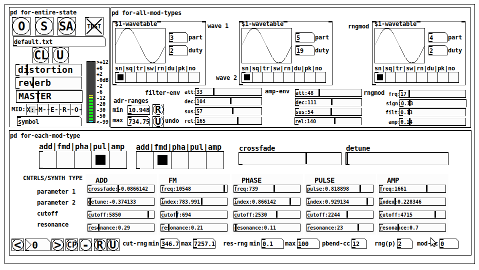
JASS is a clone-based, three wavetable, 16 voice polyphonic, Dual-channel synth.
With...
- The initial, two wavetables combined in 1 of 5 possible ways per channel and then adding those two channels. Example: additive+frequency modulation, phase+pulse-modulation, pulse-modulation+amplitude modulation, fm+fm, etc
- The third wavetable is a ring modulator, embedded inside each mod type
- 8 wave types, including a random with a settable number of partials and a square with a settable dutycycle
- A vcf~ filter embedded inside each modulation type
- The attack-decay-release, cutoff, and resonance ranges settable so they immediately and globally recalculate all relevant values
- Four parameters /mod type: p1,p2, cutoff, and resonance
- State-saving, at both the global level (wavetables, env, etc.), as well as, multiple "substates" of for-each-mod-type settings.
- Distortion, reverb
- Midiin, paying special attention to the use of 8-knob, usb, midi controllers (see below for details)
- zexy-limiters, for each channel, after the distortion, and just before dac~
Instructions
Requires: zexy
for-entire-state
- O: Open preset. "default.txt" is loaded by...default
- S: Save preset (all values incl. the multiple substates) (Note: I have Not included any presets, besides the default with 5 substates.)
- SA: Save as
- TEST: A sample player
- symbol: The filename of the currently loaded preset
- CL: Clear, sets all but a few values to 0
- U: Undo CL
- distortion,reverb,MASTER: operate on the total out, just before the limiter.
- MIDI (Each selection corresponds to a pgmin, 123,124,125,126,127, respectively, see below for more information)
- X: Default midi config, cc[1,7,8-64] available
- M: Modulators;cc[10-17] routed to ch1&ch2: p1,p2,cutoff,q controls
- E: Envelopes; cc[10-17] routed to filter- and amp-env controls
- R: Ranges; cc[10-17] routed to adr-min/max,cut-off min/max, resonance min/max, distortion, and reverb
- O: Other; cc[10-17] routed to rngmod controls, 3 wavetypes, and crossfade
- symbol: you may enter 8 cc#'s here to replace the default [10-17] from above to suit your midi-controller's knob configuration; these settings are saved to file upon entry
- vu: for total out to dac~
for-all-mod-types
- /wavetable
- graph: of the chosen wavetype
- part: partials, # of partials to use for the "rn" wavetype; the resulting, random sinesum is saved with the preset
- duty: dutycycle for the "du" wavetype
- type: sin | square | triangle | saw | random | duty | pink (pink-noise: a random sinesum with 128 partials, it is not saved with the preset) | noise (a random sinesum with 2051 partials, also not saved)
- filter-env: (self-explanatory)
- amp-env: (self-explanatory)
- rngmod: self-explanatory, except "sign" is to the modulated signal just before going into the vcf~
- adr-range: min,max[0-10000]; changing these values immediately recalculates all values for the filter- and amp-env's scaled to the new range
- R: randomizes all for-all-mod-types values, but excludes wavetype "noise"; rem: you must S or SA the preset to save the results
- U: Undoes R
for-each-mod-type
- mod-type-1: (In all cases, wavetable1 is the carrier and wavetable2 is the modulator); additive | frequency | phase | pulse | amplitude modulation
- mod-type-2: Same as above; mod-type-2 May be the same type as mod-type-1
- crossfade: Between ch1 and ch2
- detune: Applied to the midi pitch going into ch2
- for-each-clone-type controls:
- p1,p2: (self-explanatory)
- cutoff, resonance: (self-explanatory)
- navigation: Cycles through the saved substates of for-each-mod-type settings (note: they are lines on the end of a [text])
- CP: Copy the current settings, ie. add a line to the end of the [text] identical to the current substate
- -: Delete the current substate
- R: Randomize all (but only a few) substate settings
- U: Undo R
- cut-rng: min,max[0-20000] As adr-range above, this immediately recalculates all cutoff values
- res-rng: min,max[0-100], same as previously but for q
- pbend: cc,rng: the pitchwheel may be assigned to a control by setting this to a value >7 (see midi table below for possibilities); rng is in midi pitches (+/- the value you enter)
- mod-cc: the mod-wheel may be assigned to a control [7..64] by setting this value
midi-implementation
| name | --- | Description |
|---|---|---|
| sysex | not supported | |
| pgmin | 123,124,125,126,127; They set midi mode | |
| notein | 0-127 | |
| bendin | pbend-cc=7>pitchbend; otherwise to the cc# from below | |
| touch | not supported | |
| polytouch | not supported |
cc - basic (for all midi-configs)
| # | name | --- | desciption |
|---|---|---|---|
| 1 | mod-wheel | (assignable) | |
| 7 | volume | Master |
cc - "X" mode/pgmin=123
| cc | --- | parameter |
|---|---|---|
| 8 | wavetype1 | |
| 9 | partials 1 | |
| 10 | duty 1 | |
| 11 | wavetype2 | |
| 12 | partials 2 | |
| 13 | duty 2 | |
| 14 | wavetype3 | |
| 15 | partials 3 | |
| 16 | duty 3 | |
| 17 | filter-att | |
| 18 | filter-dec | |
| 19 | filter-sus | |
| 20 | filter-rel | |
| 21 | amp-att | |
| 22 | amp-dec | |
| 23 | amp-sus | |
| 24 | amp-rel | |
| 25 | rngmod-freq | |
| 26 | rngmod-sig | |
| 27 | rngmod-filt | |
| 28 | rngmod-amp | |
| 29 | distortion | |
| 30 | reverb | |
| 31 | master | |
| 32 | mod-type 1 | |
| 33 | mod-type 2 | |
| 34 | crossfade | |
| 35 | detune | |
| 36 | p1-1 | |
| 37 | p2-1 | |
| 38 | cutoff-1 | |
| 39 | q-1 | |
| 40 | p1-2 | |
| 41 | p2-2 | |
| 42 | cutoff-2 | |
| 43 | q-2 | |
| 44 | p1-3 | |
| 45 | p2-3 | |
| 46 | cutoff-3 | |
| 47 | q-3 | |
| 48 | p1-4 | |
| 49 | p2-4 | |
| 50 | cutoff-4 | |
| 51 | q-4 | |
| 52 | p1-5 | |
| 53 | p2-5 | |
| 54 | cutoff-5 | |
| 55 | q-5 | |
| 56 | pbend-cc | |
| 57 | pbend-rng | |
| 58 | mod-cc | |
| 59 | adr-rng-min | |
| 60 | adr-rng-max | |
| 61 | cut-rng-min | |
| 62 | cut-rng-max | |
| 63 | res-rng-min | |
| 64 | res-rng-max |
cc - Modes M, E, R, O
Jass is designed so that single knobs may be used for multiple purposes without reentering the previous value when you turn the knob, esp. as it pertains to, 8-knob controllers.
Thus, for instance, when in Mode M(pgm=124) your cc send the signals as listed below. When you switch modes, that knob will then change the values for That mode.
In order to do this, you must turn the knob until it hits the previously stored value for that mode-knob.
After hitting that previous value, it will begin to change the current value.
cc - Modes M, E, R, O assignments
Where [10..17] may be the midi cc #'s you enter in the MIDI symbol field (as mentioned above) aligned to your particular midi controller.
| cc# | --- | M/pgm=124 | --- | E/pgm=125 | --- | R/pgm=126 | --- | O/pgm=127 |
|---|---|---|---|---|---|---|---|---|
| 10 | ch1:p1 | filter-env:att | adr-rng-min | rngmod:freq | ||||
| 11 | ch1:p2 | filter-env:dec | adr-rng-max | rngmod:sig | ||||
| 12 | ch1:cutoff | filter-env:sus | cut-rng-min | rngmod:filter | ||||
| 13 | ch1:q | filter-env:re | cut-rng-max | rngmod:amp | ||||
| 14 | ch2:p1 | amp-env:att | res-rng-min | wavetype1 | ||||
| 15 | ch2:p2 | amp-env:dec | res-rng-max | wavetype2 | ||||
| 16 | ch2:cutoff | amp-env:sus | distortion | wavetype3 | ||||
| 17 | ch2:q | amp-env:rel | reverb | crossfade |
In closing
If you have anywhere close to as much fun (using, experimenting with, trying out, etc.) this patch, as I had making it, I will consider it a success.
For while an arduous learning curve (the first synth I ever built), it has been an Enormous pleasure to listen to as I worked on it. Getting better and better sounding at each pass.
Rather, than say to much, I will say this:
Enjoy. May it bring a smile to your face.
Peace through love of creating and sharing.
Sincerely,
Scott
posted in patch~
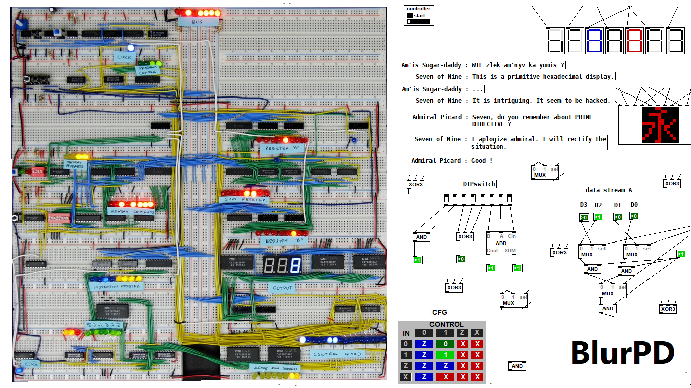
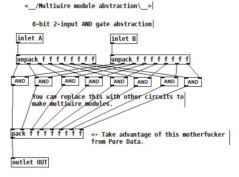
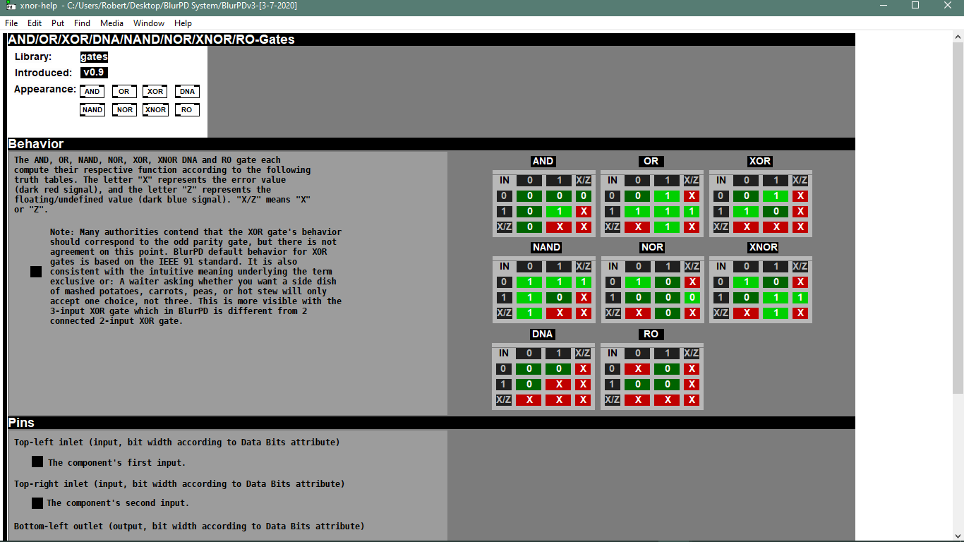
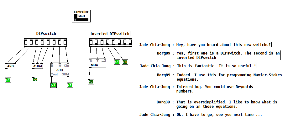
BlurPD - digital logic framework system for Pure Data [v3]
BlurPD is a framework system to extend Pure Data with the ability to make
digital logic circuits while taking advantage of the DSP capabilities of Pure Data. In order to design and simulate interesting circuits, ASIC chips, DSP processors or entire CPU's, all in Pure Data. It is made from jucy fundamental modules (Lego blocks) that when put together turn Pure Data into a madness of bits ...
Bug Fixes & Notes [v3]
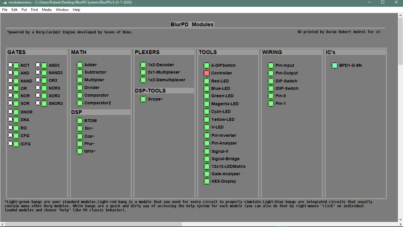
Modules [v3]
- GATES : not,and,nand,or,nor,xor,xnor,cfg,icfg,dna,ro,and3,or3,nand3,nor3,xor3,xnor3
- PLEXERS : 2x1multiplexer,1x2demultiplexer,1x2decoder
- MATH : adder,subtractor,multiplier,divider,comparator,comparator2
- IC : bpd1g8n (integrated 8xNAND gates)
- TOOLS : redled,blueled,greenled,yellowled,magentaled,cyanled,sigv,pininv,gateanalyer
ledmatrix,controller,adipswitch,vled,hexdisplay,sigbridge,pinanalyzer - WIRING : pininput,pinoutput,pin0,pin1,dipswitch,idipswitch
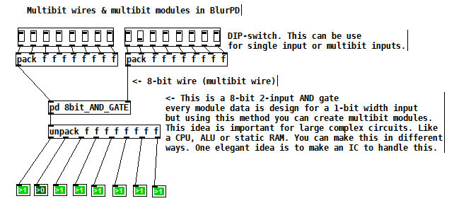
- MODULES : the core library for BlurPD built-in modules
- ICMODULES : the core library for "IC" modules
- DSP : btom,sin~,pha~,ipha~,cos~
- DSPTOOLS : scope~
New Stuff [v3]
- Changes to the Help system. Better GUI and integration [v3]
 patch download
BlurPDv3-[3-7-2020].zip
 BlurPD archive (older versions)
BlurPDv2.9-[3-3-2020].zip
BlurPDv2.8-[3-3-2020].zip
BlurPDv2.7-[3-3-2020].zip
BlurPDv2.6-[3-1-2020].zip
BlurPDv2.5-[2-29-2020].zip
BlurPDv2.4-[2-27-2020].zip
BlurPDv2.3-[2-26-2020].zip
BlurPDv2.2-[2-25-2020].zip
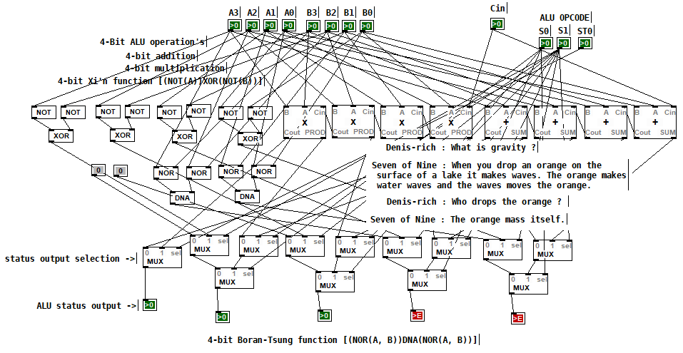
Multibit modules for more complex circuits [v3]
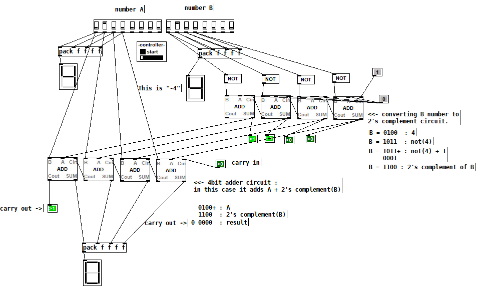
4-bit Boran-Tsung function using a 4-bit ALU (arithmetic logic unit) circuit made with BlurPD [v3]
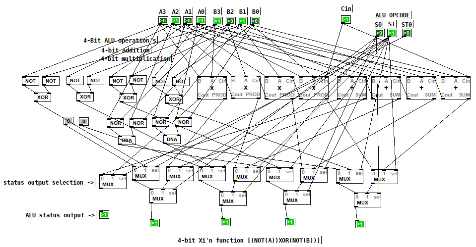
4-bit Xi'n function using a 4-bit ALU circuit made with BlurPD [v3]
Snapshot of the modules system and help system [v3]
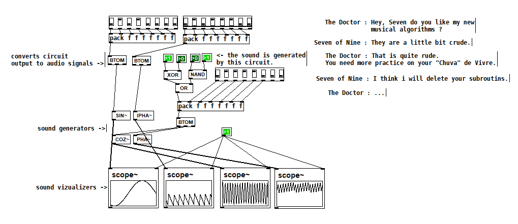
Making generative sounds using new DSP modules [v2.9]
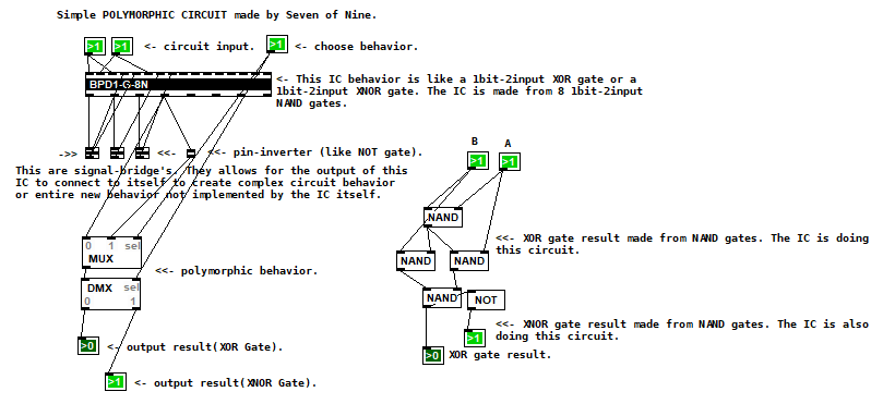
Polymorphic circuit [v2.7]
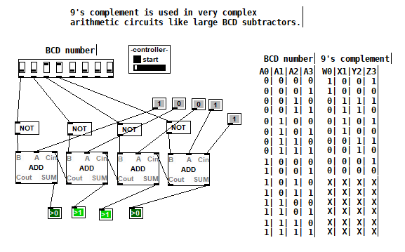
Application 1 of BlurPD system from [v2.3]
Application 2 of BlurPD system from [v2.3]
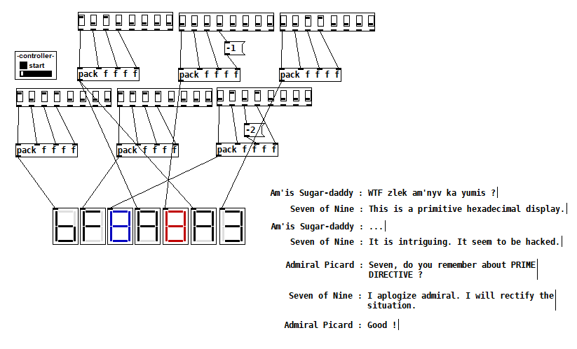
Hexadecimal display [v2.3]
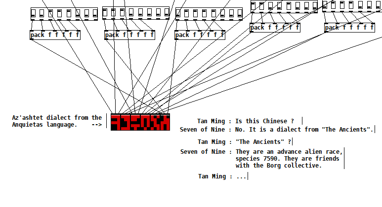
The Ancients [v2.2]
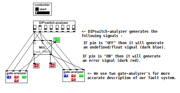
Complex analysis using a DIP-switch analyzer [v2.1]
DIPSwitch from [v2.0]
posted in patch~
3-op FM synth with mod matrix
@RandLaneFly Hi, I'll do my best to give you some replies:
- yes, offset just adds a fixed frequency in hertz regardless of the ratio or the note played. It's useful if you want to use an operator as an LFO;
- I used clip because the patch can receive values from external messages from the parent patch, the clip avoids unwanted values whatever you send to it. It's got to do with the GUI of the patch rather than with the synth itself;
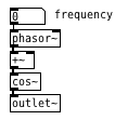
- here is pphasor~.pd, it's just a phasor with sample accurate phase reset to be able to sync the operators accurately. I adapted it from some old patch I found, but I can't remember what I've changed to be honest. It only replaces phasor~ so you'd still need cos~ afterwards;
- about wrap~ and cos~: in a normal situation, where you do phase modulation with phasor and cos~, you don't need wrap~ because cos~ already wraps whatever phase it receives, even if it's outside the 0..1 range. In this case, instead of cos~, I used a table to store the waveform. Two reasons for this: 1) I wanted to be able to change the resolution of the sine and 2) I wanted to be able to use other waveforms other than a sine wave. Having said that, if your phase (after being scrambled around by all the modulators acting on it) has to address a table, you need it to be within the range of that table, otherwise you would be addressing points that are outside of the table (which would result in silence). This is why the phase is wrap~ped to the 0..1 range, and then multiplied by the length of the table in samples (4096 in this case);
- I don't understand what you mean by:
@RandLaneFly said:
But I take it after that it's sending out the phases to the tables, what is the purpose of the line being formed and sent into the right inlet?
The tabread4~ object is your output waveform for this specific operator you're looking at. Afterwards it's multiplied by the envelope (received on the right inlet of the *~ object), and then it's sent to the output (aka, what you hear) and to the phase tables.
- If by "the math in the table patch" you mean the fexpr~ object, that is exactly the same as found in the thread I mentioned in the first post. It averages the last two samples in order to filter very high, harsh frequencies in the feedback path. It's possible that FM8 uses a different filter, which would result in a different sound, but I have no way of knowing that.
I'm afraid the only resource I used for making this mess of a patch was that single thread about feedback, and then I expanded it for multiple operators. I very much like how it sounds, but it's incredibly expansive with polyphony, and on my computer 3 operators seem to be the limit, I wanted to try six but could never manage.
 posted in abstract~
3-op FM synth with mod matrix
@zxcvbs Hi, yes I realise the patch is very counterintuitive, I'll do my best to try and explain what's going on. Let's forget about polyphony and consider one voice.
The PMops abstraction is the single voice, inside it are the three operators (PMop, both badly named sorry) and the tables subpatch. The basic structure of each operator could be reduced to the simple:
but the +~ object, instead of receiving the phase from a fixed modulator, it receives it from a table. Each operator has its own table, so operator 1 receives the phase from tabreceive~ $0-phase1 which is connected to +~.
At the same time (to populate those tables), the output from cos~ of each operator is sent to all tables, how much of the signal goes to each is decided in the modulation matrix.
The reason I decided for this arrangement is because this way each operator can send its phase to any operator, including itself (feedback). As explained in the first post, feedback has to be done with the operator working at block~ 1 in order to sound good, but if an operator receives the feedback every sample (block~ 1) but to that you add the phase of the other modulators every 64 samples (the default block size), the result sounds bad. This is the reason I used this mess of tables, to have an FM-8 style modulation matrix.
If you want to implement hard-coded algorithms, the same thing can be done without tables, patching each algorithm in its own abstraction or subpatch and switch between them as @whale-av suggested in your thread. Plus I see none of your algorithms have feedback, so they don't even need to run at block~ 1, and therefore the approach with tables is really not necessary.
Hope this clarifies things a bit.
posted in abstract~
Cannot get Pyata to work
This error statement TypeError: 'module' object is not callable is raised as you are being confused about the Class name and Module name. The problem is in the import line . You are importing a module, not a class. This happend because the module name and class name have the same name .
If you have a class "MyClass" in a file called "MyClass.py" , then you should import :
from MyClass import MyClass
In Python , a script is a module, whose name is determined by the filename . So when you start out your file MyClass.py with import MyClass you are creating a loop in the module structure.
In Python, everything (including functions, methods, modules, classes etc.) is an object , and methods are just attributes like every others. So,there's no separate namespaces for methods. So when you set an instance attribute, it shadows the class attribute by the same name. The obvious solution is to give attributes different names.
 posted in technical issues
FM stacked modulators
@roman.galyaminskiy Hi, what you are doing in the patch is "true" frequency modulation, in that you are modulation the frequency of [osc~] objects. Generally the way to do it in software (and indeed how it's done in the DX7, volca etc) is called phase modulation, which is analogous to FM, where instead you modulate the readout phase of cosine oscillators. This approach also allows you to have an oscillator modulating itself (which you need for operator 6 in the algorithm you are trying to emulate), although that needs to happen on a sample-by-sample basis, and you need to use the block~ object inside a subpatch for that.
I fixed your patch to do phase modulation, and now has 6 operators (number 6 has feedback). It probably won't sound exactly like the volca because you are missing a number of features (envelopes, frequency offset, phase locking etc), but it should get you started with exploring FM in Pd, hope it helps.
fm_mod_stack_fix.pd
I attempted to recreate this sort of thing some time ago, with a flexible algorithm structure. It's pretty involved and not intuitive at all, but it's basically the same concept as the above patch. It's a CPU hog enough with only 3 operators, but it sounds pretty good to me.
https://forum.pdpatchrepo.info/topic/10745/3-op-fm-synth-with-mod-matrix
posted in technical issues
3-op FM synth with mod matrix
@djpersonalspace Thanks for sharing the patch you're working on. I should point out that your patch uses "real" FM, which means that you directly modulate the frequency of an osc~, whereas my patch (like most implementations of FM) uses what is called "phase modulation", where you modulate the phase lookup of a sine wave instead. This is a key difference to understand if you are trying to implement multi-operator FM.
For the basics on this, have a look at help > browser > pure data > 3.audio.examples > E08.phase.mod.pd
This is what my mod matrix is doing in the patch, there is one table which holds the phase of each operator, and every time some other operator is sent to modulate it by some amount (aka the modulation index), the output of this modulator is added to the table along with all the others that are set to modulate it. I think that once you understand the difference between FM and PM this becomes clearer.
You could do all this in a simpler way with s~, r~, throw~ and catch~. The reason I'm doing all this madness with tables here is because I wanted to have feedback as well for each operator, and in order to do so the phases need to be updated sample by sample, whereas s~ and r~ objects only work in chunks of 64 samples. That doesn't sound right when you try it.
posted in abstract~