How to loop/reset an audio file to the beginning
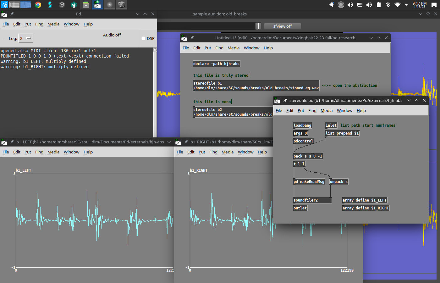
To clarify: Here, into [stereofile b1 ...] I've loaded a two-channel file, and into [stereofile b2 ...], a one-channel file.
Step 1. Open the b1 abstraction.
Step 2. (Don't enable edit mode) -- click on [array define $1_LEFT].
Step 3. Click on [array define $1_RIGHT].
Step 4. See that both arrays contain audio.
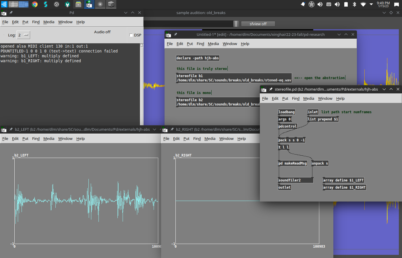
Step 5. Open the b2 abstraction.
Step 6. (Don't enable edit mode) -- click on [array define $1_LEFT].
Step 7. Click on [array define $1_RIGHT].
Step 8. See that the left array contains audio while the right array contains nothing.
[monofile] and [stereofile] pass messages to [soundfiler]... so you could test also like this:
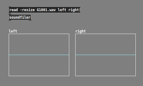
^^ this is the correct way to load a stereo file into soundfiler (note, I didn't actually run it in this patch, hence the empty audio -- but this is the right method!). But your original screenshot doesn't do this. Your original patch loads the left channel twice (which is just wasting memory btw).
hjh
 posted in technical issues
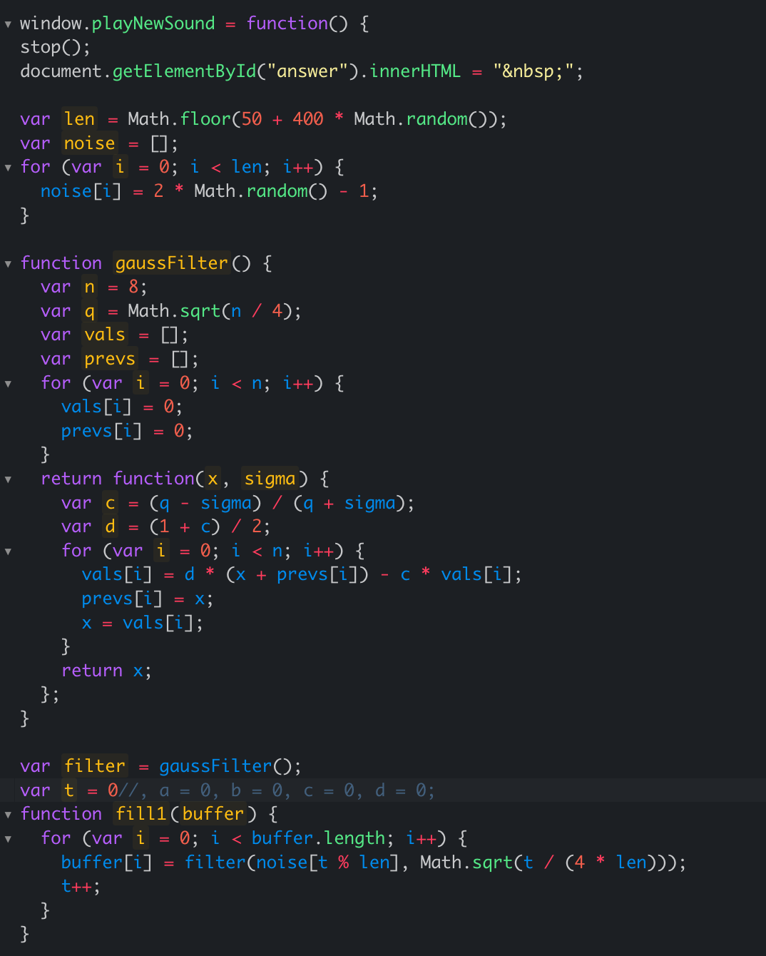
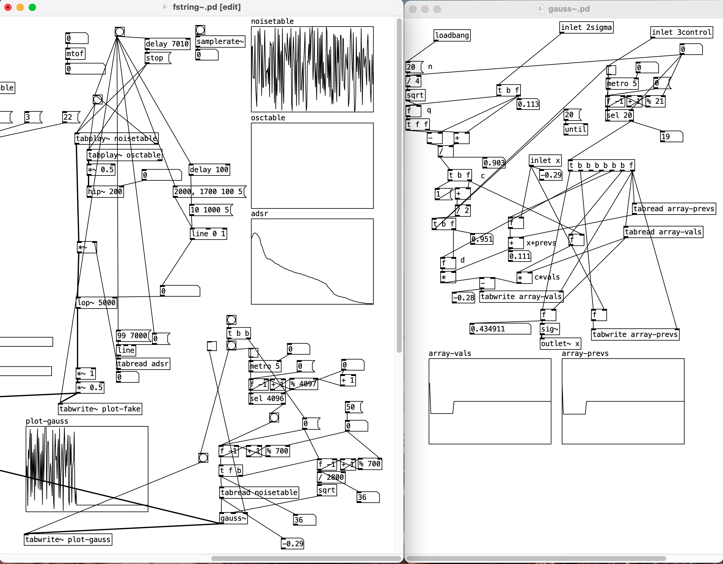
Karplus-Strong alternative help
I found this reddit post regarding an alternative to the karplus-strong algorithm to generate string sounds. But the snippet provided is in javascript. I tried implementing it in pd but am having a tough time transferring all the JS idioms into pd. Kindly help. Also, please skip the suggestion of using [expr].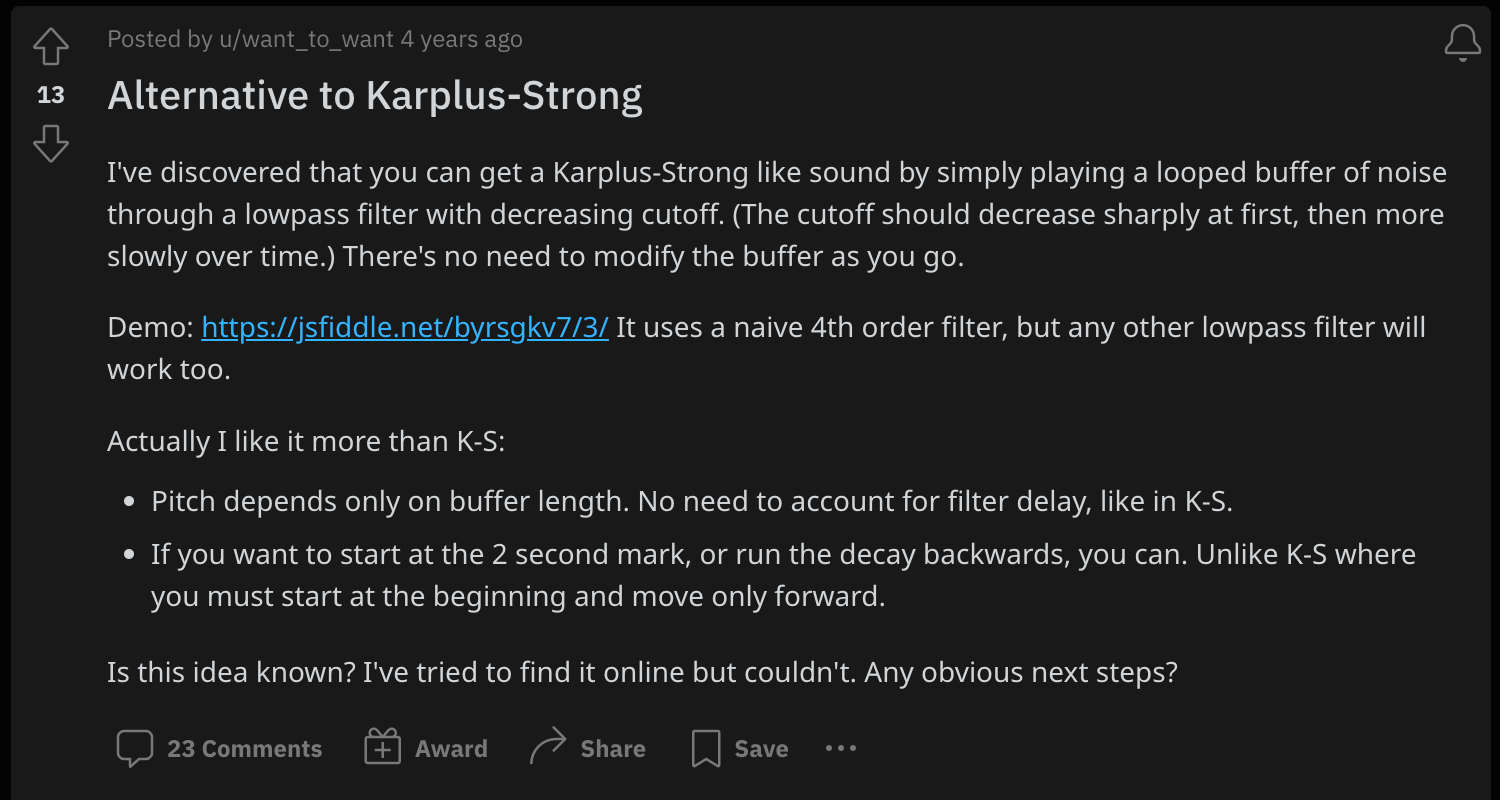
 posted in technical issues
help with polyphonic synth
I realized, after posting that, that there are two ways of thinking about the "extra parameters" going into the synth clone, which for lack of a better term I could call "global" vs "local" parameters.
Local parameters are "per-note" -- they are set at the time the note begins, and they hold their value for the duration of the note. The next note (which might overlap) could have completely different values.
Global parameters affect all notes simultaneously. This is the usual way that, for instance, filter frequency works. You twist the filter cutoff knob and all notes' cutoff changes simultaneously (even though each note could have its own filter cutoff envelope).
At minimum, pitch (note number or frequency) and velocity (on/off trigger) should be per-note. Other parameters could be global or local (and you can mix those styles).
As far as I can see, the best way is:
- All local parameters get packed into a list, along with the clone instance number (which is supplied by [poly]). The "local" list goes into the leftmost input, and only the leftmost.
- "Global" parameters add one or more inlets to the right. Note carefully in the [clone] help file that control inlets need to tag their values for specific instances. If we're using these as global parameters, then the tag should be
all. Signal inlets are always global.
IMO it's best to be consistent about the handling of these input types, to avoid introducing bugs into your patch.
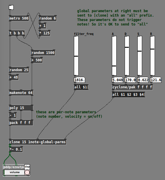
Example with filter cutoff and envelope parameters treated globally:
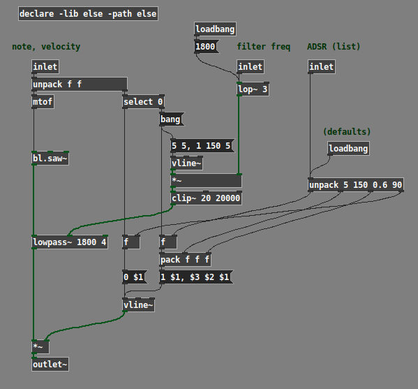
Example with filter cutoff and envelope parameters treated locally:
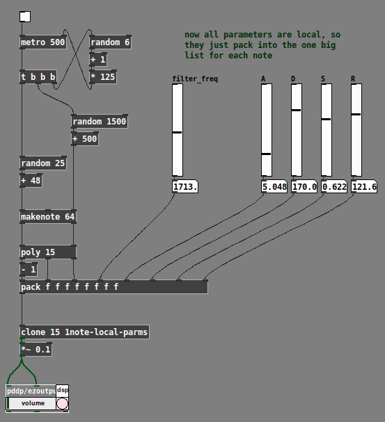
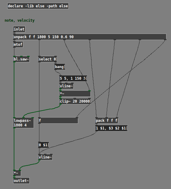
(Note: The example patches use the ELSE external library, and the global one uses cyclone.)
Hope this helps. IMO polysynth is a basic use case for any audio programming environment; if what I've posted here can't be easily figured out from the documentation, then it suggests a gap in the help. (One reason why I worked it out is that I teach a class in Pd; if the students ask "how do I make a poly synth?" then I'd better have an answer at the ready. So I tried a few ways and came up with this as a basic template that Just Works... then, just do it that way.)
hjh
posted in technical issues
faustgen~ - the FAUST compiler embedded in a Pure Data external
Hi all
@Pierre-Guillot this is a terrific project
Thanks for sharing!
I've been using the HOA library and some older stuff form you and others at CICM
Now, I've installed from Deken the faustgen~ object, and as soon as I open the faustgen~-help.pd it delivers tons of errors to the console:
menu_doc_open /Library/Pd/faustgen~ faustgen~-help.pd
/Library/PD/faustgen~/faustgen~.pd_darwin: dlopen(/Library/PD/faustgen~/faustgen~.pd_darwin, 10): Library not loaded: @rpath/libRemarks.dylib
  Referenced from: /Library/PD/faustgen~/faustgen~.pd_darwin
  Reason: image not found
/Library/PD/faustgen~/faustgen~.pd_darwin: dlopen(/Library/PD/faustgen~/faustgen~.pd_darwin, 10): Library not loaded: @rpath/libRemarks.dylib
  Referenced from: /Library/PD/faustgen~/faustgen~.pd_darwin
  Reason: image not found
/Library/Pd/faustgen~/faustgen~.pd_darwin: dlopen(/Library/Pd/faustgen~/faustgen~.pd_darwin, 10): Library not loaded: @rpath/libRemarks.dylib
  Referenced from: /Library/Pd/faustgen~/faustgen~.pd_darwin
  Reason: image not found
 faustgen~ examples/gain -vec -lv 1
... couldn't create
... you might be able to track this down from the Find menu.
/Library/PD/faustgen~/faustgen~.pd_darwin: dlopen(/Library/PD/faustgen~/faustgen~.pd_darwin, 10): Library not loaded: @rpath/libRemarks.dylib
  Referenced from: /Library/PD/faustgen~/faustgen~.pd_darwin
  Reason: image not found
/Library/PD/faustgen~/faustgen~.pd_darwin: dlopen(/Library/PD/faustgen~/faustgen~.pd_darwin, 10): Library not loaded: @rpath/libRemarks.dylib
  Referenced from: /Library/PD/faustgen~/faustgen~.pd_darwin
  Reason: image not found
/Library/Pd/faustgen~/faustgen~.pd_darwin: dlopen(/Library/Pd/faustgen~/faustgen~.pd_darwin, 10): Library not loaded: @rpath/libRemarks.dylib
  Referenced from: /Library/Pd/faustgen~/faustgen~.pd_darwin
  Reason: image not found
 faustgen~ examples/dummy
... couldn't create
/Library/PD/faustgen~/faustgen~.pd_darwin: dlopen(/Library/PD/faustgen~/faustgen~.pd_darwin, 10): Library not loaded: @rpath/libRemarks.dylib
  Referenced from: /Library/PD/faustgen~/faustgen~.pd_darwin
  Reason: image not found
/Library/PD/faustgen~/faustgen~.pd_darwin: dlopen(/Library/PD/faustgen~/faustgen~.pd_darwin, 10): Library not loaded: @rpath/libRemarks.dylib
  Referenced from: /Library/PD/faustgen~/faustgen~.pd_darwin
  Reason: image not found
/Library/Pd/faustgen~/faustgen~.pd_darwin: dlopen(/Library/Pd/faustgen~/faustgen~.pd_darwin, 10): Library not loaded: @rpath/libRemarks.dylib
  Referenced from: /Library/Pd/faustgen~/faustgen~.pd_darwin
  Reason: image not found
 faustgen~ examples/gain
... couldn't create
/Library/PD/faustgen~/faustgen~.pd_darwin: dlopen(/Library/PD/faustgen~/faustgen~.pd_darwin, 10): Library not loaded: @rpath/libRemarks.dylib
  Referenced from: /Library/PD/faustgen~/faustgen~.pd_darwin
  Reason: image not found
/Library/PD/faustgen~/faustgen~.pd_darwin: dlopen(/Library/PD/faustgen~/faustgen~.pd_darwin, 10): Library not loaded: @rpath/libRemarks.dylib
  Referenced from: /Library/PD/faustgen~/faustgen~.pd_darwin
  Reason: image not found
/Library/Pd/faustgen~/faustgen~.pd_darwin: dlopen(/Library/Pd/faustgen~/faustgen~.pd_darwin, 10): Library not loaded: @rpath/libRemarks.dylib
  Referenced from: /Library/Pd/faustgen~/faustgen~.pd_darwin
  Reason: image not found
 faustgen~ examples/parameters
... couldn't create
/Library/PD/faustgen~/faustgen~.pd_darwin: dlopen(/Library/PD/faustgen~/faustgen~.pd_darwin, 10): Library not loaded: @rpath/libRemarks.dylib
  Referenced from: /Library/PD/faustgen~/faustgen~.pd_darwin
  Reason: image not found
/Library/PD/faustgen~/faustgen~.pd_darwin: dlopen(/Library/PD/faustgen~/faustgen~.pd_darwin, 10): Library not loaded: @rpath/libRemarks.dylib
  Referenced from: /Library/PD/faustgen~/faustgen~.pd_darwin
  Reason: image not found
/Library/Pd/faustgen~/faustgen~.pd_darwin: dlopen(/Library/Pd/faustgen~/faustgen~.pd_darwin, 10): Library not loaded: @rpath/libRemarks.dylib
  Referenced from: /Library/Pd/faustgen~/faustgen~.pd_darwin
  Reason: image not found
 faustgen~ examples/resonator
... couldn't create
Tries uninstalling, but nothing.
Any clue?
Thanks in advance.
Best,
Alexis
 posted in news
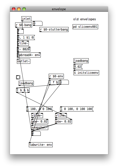
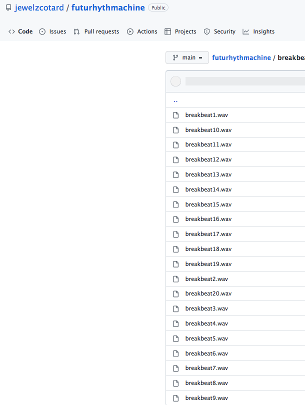
Futurhythmachine (drum mangler type patch)
Hi the features of your patch in the video are astonishing!
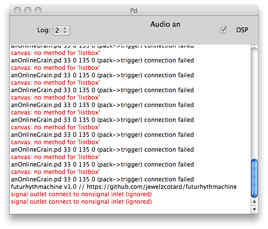
But i downloaded the patch and first the wav files are adressed wrongly. In the patch the wav files are declared as breakbeats_breakbeatX but the wavs in the wav folder are in the format breakbeatX. I changed that now the wav files are read correctly. Nevertheless I dont get any sound out of the patch. I followed your instructions. . And something is wrong with the env abstraction perhaps? I get these error messages
BEst Regards
 posted in patch~
How to use multiple audio devices (input)?
@s.elliot.perez My setup looks like this..... but different soundcards of course...... and only 2 including the built-in Realtek.
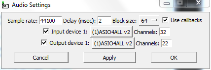
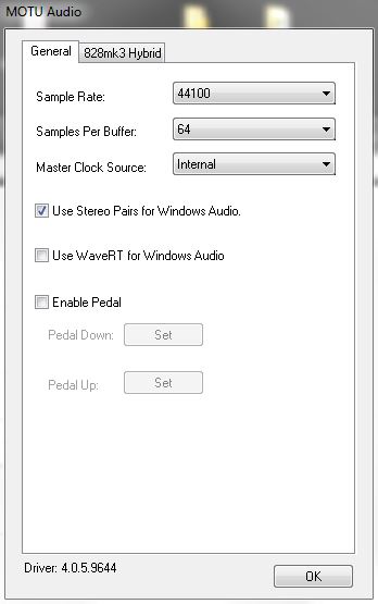
I needed very low latency.... so extreme Delay (msec) of 2 setting for Pd....... and an ASIO buffer of 64.
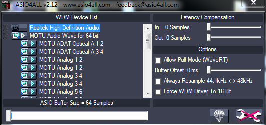
I notice that I have selected all the stereo pairs for the Motu...... rather than the "whole device" that you have chosen for the GP-10.
I would try turning on only one device at a time in Asio4all and making sure that the buffer sizes all match in the dedicated control panels for those soundcards that have one. But I think you posted that the buffers matched.
Ticking the callbacks box in Pd might help.
I cannot see anything "wrong" in your screenshots.
You could try using this DPC latency checking program to see if interrupts or dodgy drivers are causing problems.........DPC latency check.zip
Lastly, modern computers often use internal usb ports for the mouse, keyboard, bluetooth etc.
Changing external port so that you are using a different hub could also help.
Where are you hearing the glitches.... on one device or all?
David.
 posted in technical issues
Puredata on android phone using andronix: no sound!
Hello everyone!
I'm trying to make pd work on an android phone using Andronix, with no luck so far. I have compiled from source, but I do not hey any sound devices!
Here are some screenshots I hope can give some clues of the issue...
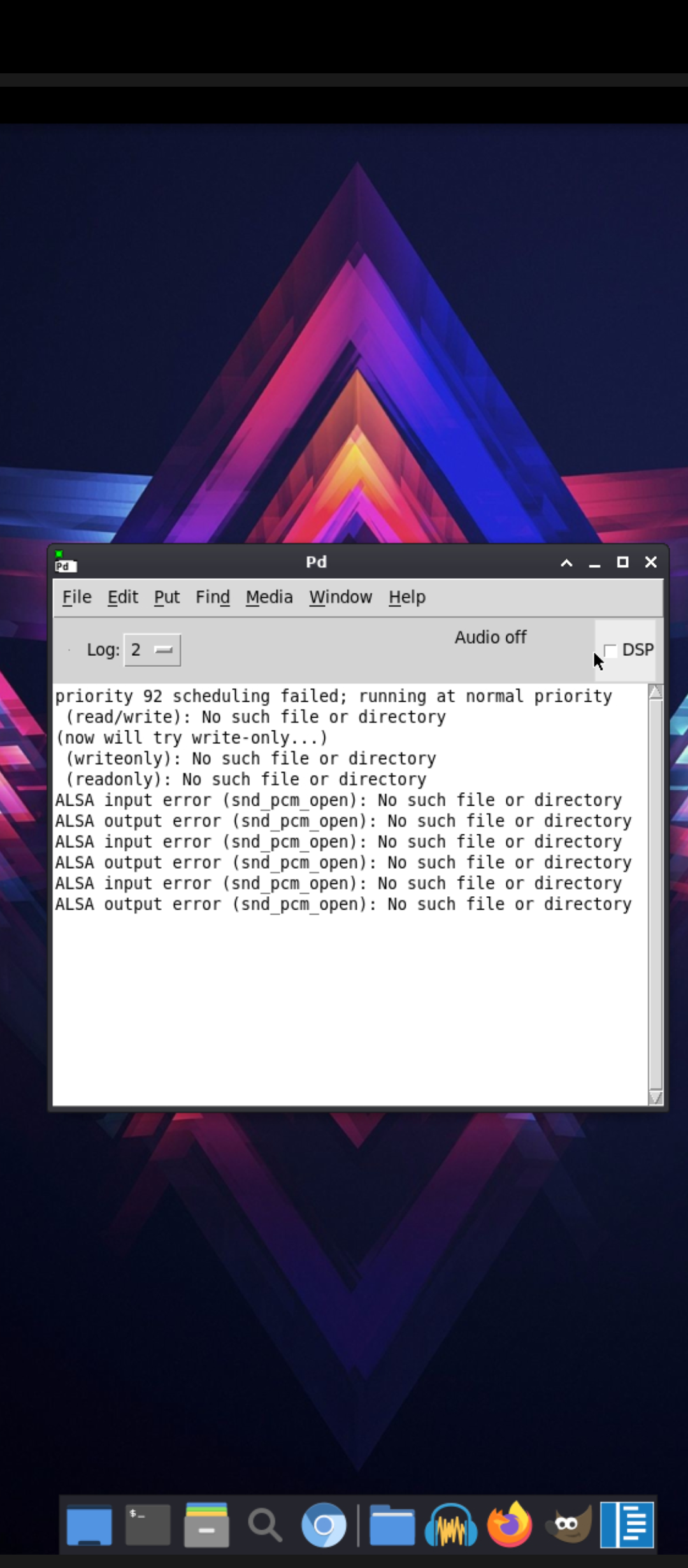
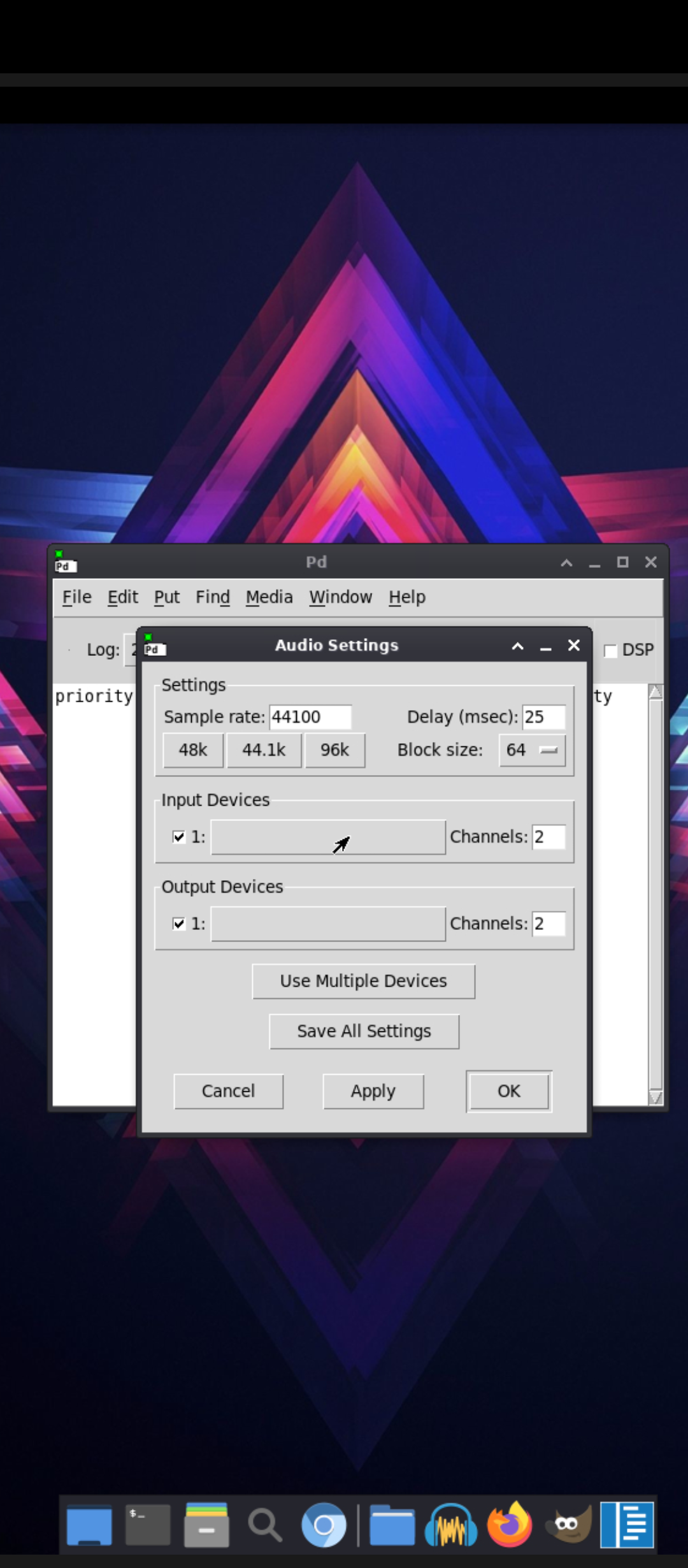
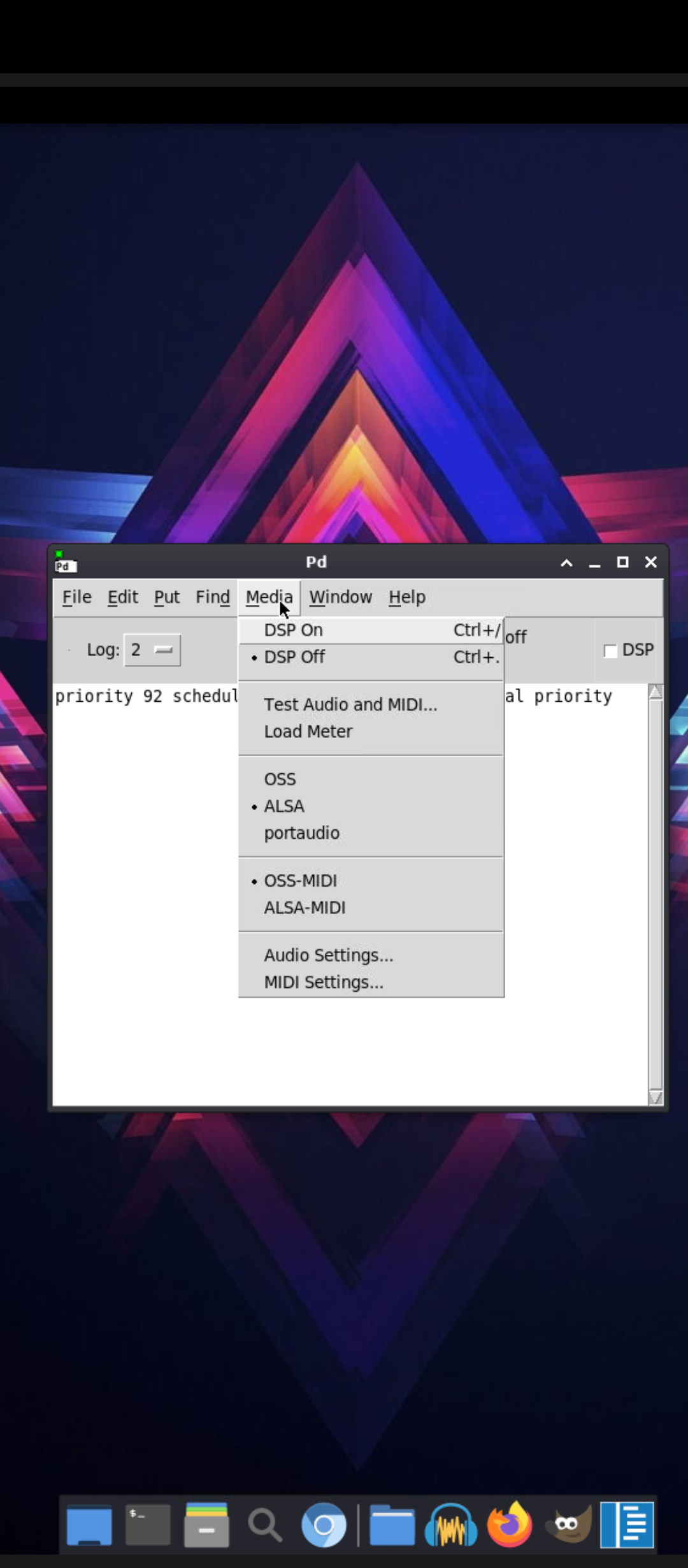
I also installed in Ubuntu from the repositories and had similar issues. What could I do to fix this? Thanks in advance!!
 posted in technical issues
I'm trying to build filters with [pole~] [zero~],but I'm so confused with the factorization of the two-zero transfer function:
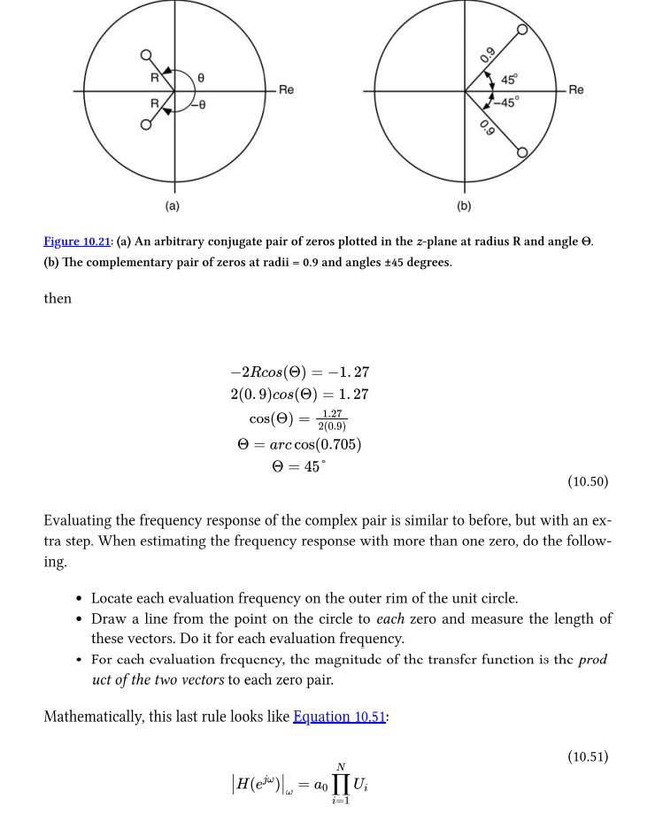
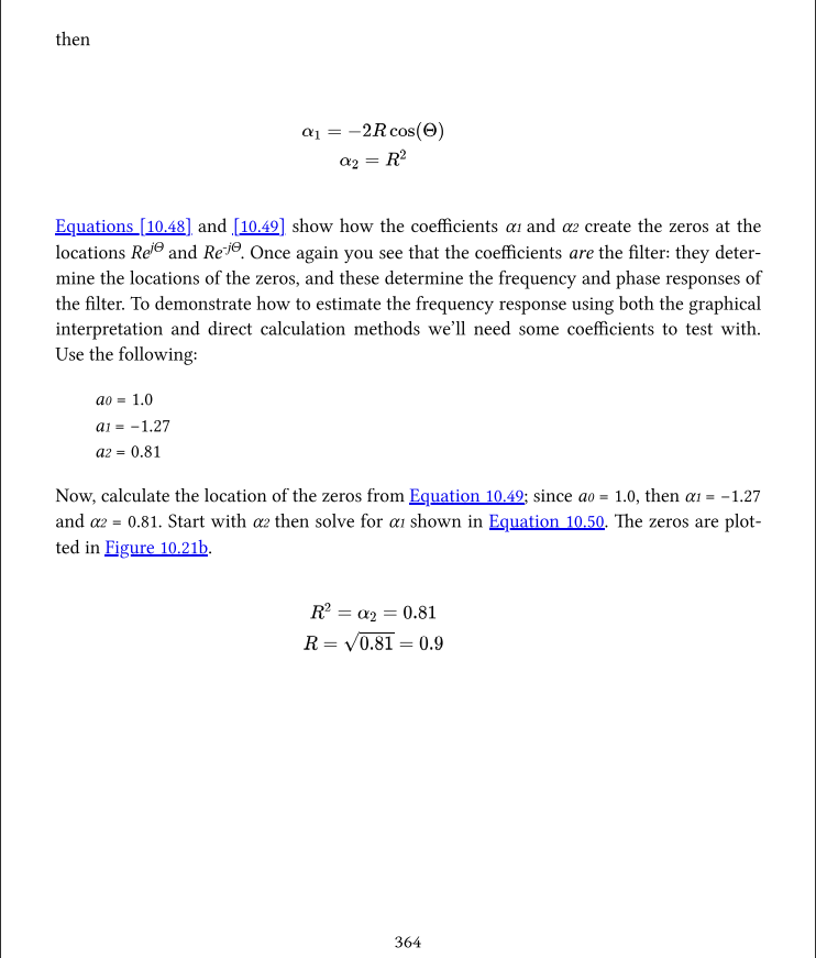
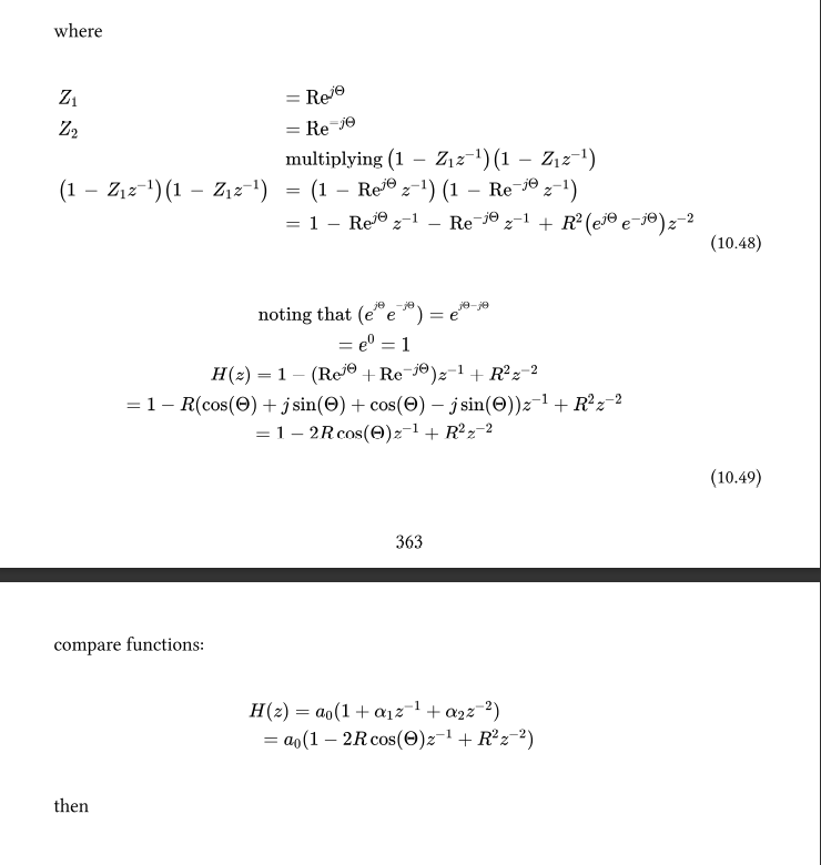
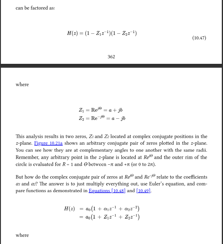
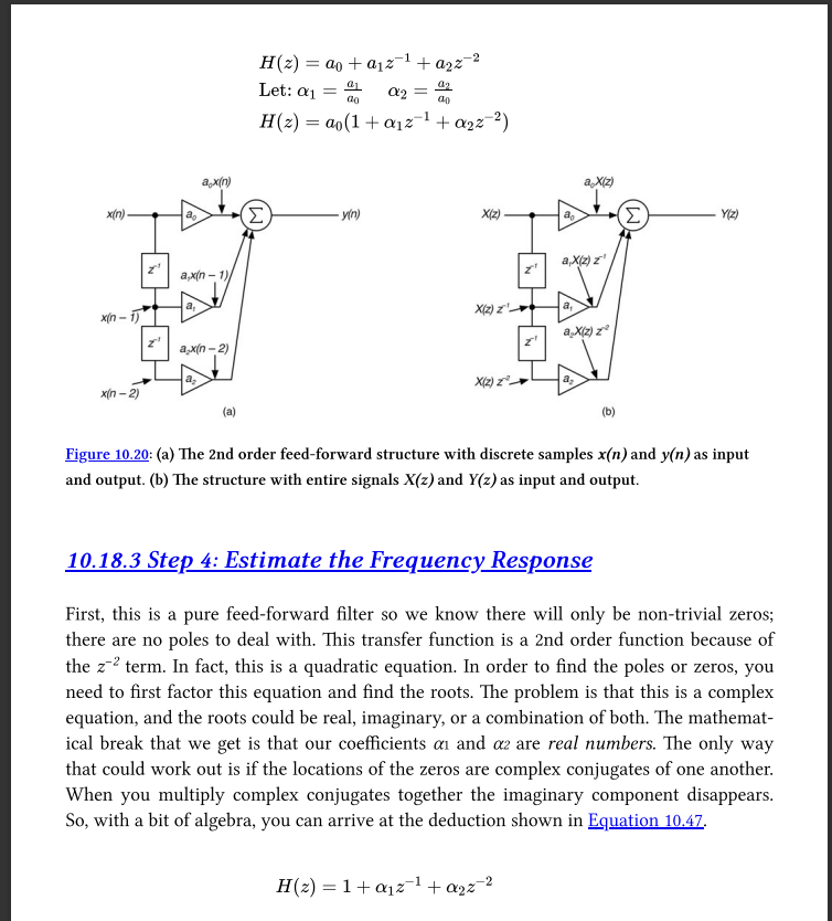
I tryed to use Cross multiplication and Conjugate roots to factor the transfer function of two-zero feed-forward filter but...I can‘t get the result like :
(1-Z1z^-1)(1-Z2z^-2) on p362.
The name of the book is Designing Audio Effect Plugins in C++
Same function can be found here but no explation about how to factor:https://ccrma.stanford.edu/~jos/filters/Two_Zero.html
 posted in technical issues
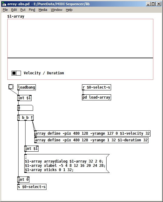
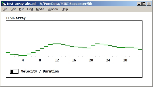
Question about muliple arrays in one graph
I decided to redesign the thing, taking a different approach. Rather than try to display two arrays in the same graph, I defined one array (named "$1-array"), the only one which actually gets displayed, using the Put menu. Then I defined two other arrays (named "$1-velocity" and "$1-duration") using [array define], and a horizontal radio button to allow the user to select which of the two arrays to display. When the user clicks on one of the radio button selections, it saves the current contents of $1-array and then copies the contents of the selected array into $1-array.
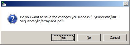
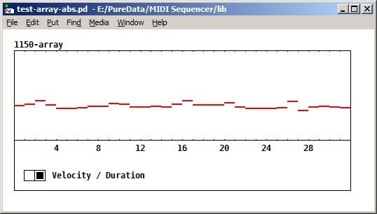
It works the first time I open the patch, but when I go to close it, PD asks me if I want to save my changes (even though I didn't make any changes, except to the data in the arrays. I don't have "Save contents" checked either. If I say "No", I can open the patch again and it still works. But if I say "Yes", it replaces the original name of the displayed array ("$1-array") with the actual number (for example, "1150-array", as in the screen print below) inside the patch. I'm not sure why it's doing this, or if it's expected behaviour. It doesn't over-write the names of the other two arrays ($1-velocity and $1-duration) inside the patch, though. Any ideas?
The whole thing is getting a little complicated, so I've uploaded the parent patch ("test-array-abs.pd") and the abstraction containing the arrays ("array-abs.pd"). This is the line in "array-abs.pd" that gets changed if I say "Yes". Of course, I could try to remember never to say "Yes", but that's a bit much to ask of the user, I think. And it's kind of annoying to have to answer in the first place.
Before:
#X array \$1-array 32 float 2;
After:
#X array 1161-array 32 float 2;
 posted in technical issues
Contribute to better Pd Documentation
As a Puredata teacher in a fine art school since 10years (and many workshops in China) the only solution for me to make pd "usable" by my students, was to distributed my own puredata version modified with translated help files from an "computer-scientist" to an "artist" point of view, and with many extra things.
@whale-av said:
Maybe adding a "Documentation" link to the console help menu would be a good first move....?
I agree, if only clickable link could be added to console.
The doc subfolder names are not enticing..... "3.audio.examples" really could be "3.digital.audio.tutorial" for example.
I don't think there is even a link to it in the "HTML Manual" which becomes "PD Documentation" when it is opened.
All very confusing though as the Pd.doc folder is mostly a patching tutorial that complements the Floss manual.
I agree, the documentation could a bit more explicit and well organised. I simply don't use it and added mine.
Finally, Here is an example of my pd version that I throw to students now to have a chance to keep them in the game:
-
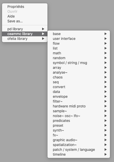
I am using ceammc a lot, and added some objets and a simple theme:
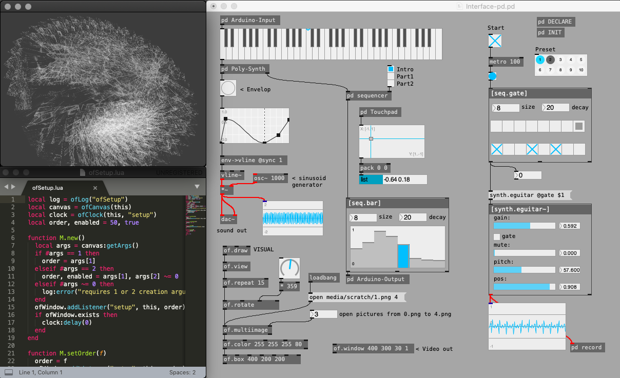
-
I added a template for every new patches and some personnal icons to ceammc bar:
-
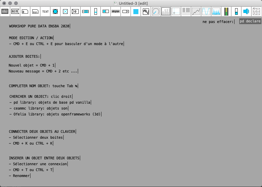
Here is my Intro-help.pd (accessible from any right clic in a patch)
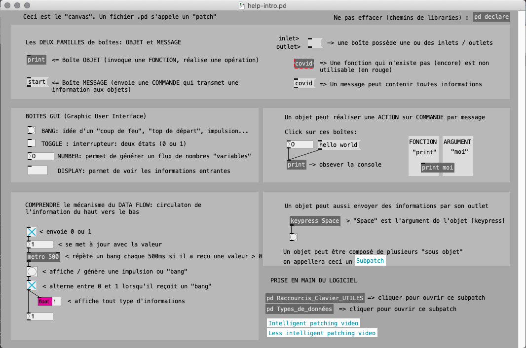
-
I added my own fast prototyping ofelia abstractions:
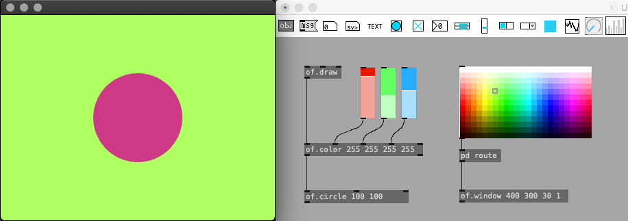
-
The right click show all the objects (also have auto-completion of course)
I think right-click on objects should propose "Online Reference" that lead to an online up-to-date documentation... or wiki.
 posted in tutorials