instance specific dynamic patching documentation assistance
@whale-av @ben.wes @ddw_music
I am learning about dynamic patching. The documentation describes instance specific dynamic patching as being able to send messages to a specific instance of an abstraction, by renaming the abstraction using namecanvas. The renaming can be automated using $0 expansion.
I am not familiar with where to locate namecanvas and how to use it and I am not familiar with how to use $0 expansion. Can someone please show a complete visual example of how to use instance specific dynamic patching using the exact instructions given in the documentation link?
https://puredata.info/docs/tutorials/TipsAndTricks#instance-specific-dynamic-patching
And can someone show a visual example of how to use dynamic patching to dynamically create instances of an object in an abstraction? For example, if I create a patch with a sine oscillator that can be assigned a frequency, an amplitude, and has a dac object and then make that patch an abstraction how would I be able to use dynamic patching to allow my gui to let me assign a new sound source in place of the sine oscillator? Objects like the switch object have limitations. I would want to be able to assign/unassign any number of new sounds sources in place of the sine oscillator. For example a phasor object, a noise object, or even synthesizer patch abstraction. Suggestions for other ways to do this are good and I also want to be sure to have explanations for using dynamic patching since that is what I am learning. How could this be done using dynamic patching?
General Dynamic Patching
What is the difference between pd messages and patch messages? Are they both used for dynamic patching? And how are they different from instance specific dynamic patching?
https://puredata.info/docs/tutorials/TipsAndTricks#pd-messages
https://puredata.info/docs/tutorials/TipsAndTricks#patch-messages
 posted in technical issues
understanding a simple feedback oscillator
I was just experimenting with the “classic” feedback FM and stumbled on a related technique that seems quite interesting to me, especially because of its chaotic behavior. It’s actually very simple: The output of an oscillator is delayed and, scaled by some factor, fed back into that same oscillator as its frequency. So there is no external input, no carrier frequency (or a zero carrier frequency if you will), which means that it is a symmetric “through-zero” FM.
By guessing I figured out how the delay time determines the frequency of the oscillator, but I still don’t understand a few things: Why is there a factor of 4 involved so that the delay is one quarter of a cycle? And why is there still some error? I found two ways to fix it, first by oversampling and second by reducing the delay time by the duration of one half sample. To be honest I don’t have a clue why this works ... Any ideas?
What I find particularly interesting is the path from sinusoidal tones at modulation index 1 (which seems to be a critical value) to different modes of periodic oscillation and finally to chaos when the modulation index is increased: First odd harmonics are added, then even harmonics, then a period doubling or “bifurcation” occurs, and shortly after that we get into the chaotic region. This seems to be not too different from the logistic map or related chaotic maps. So I’m wondering if it’s possible to analyze the oscillator in terms of chaos theory to better understand and control its behavior.
Apart from being mathematically interesting, I think this could also be a usable noise generator with spectral control. Other effects can be achieved by adding an external input ... but for now, I’m more interested in understanding that simpler case.
 posted in patch~
Linked abstractions, synth experiment
Hello,
I am new to puredata, just started very recently and still learning how the language works.
I created a minimoog style oscillator where I can change certain parameters like: waveform, fine tuning, panning, volume. This file I named oscillator.pd, after which I created a "synth.pd" file that basically uses two "oscillator.pd" as an abstraction.
The problem is the following: when I modify one oscillator it also modifies the other, so I can't use them separately but it's as if they are linked together.
I attach the files, thanks in advance for the help!
Agustin Davrieux
 posted in technical issues
3rd Release Candidate of ELSE 1.0-0 (with Live Electronics Tutorial)
HEY!!! I'm really proud of this one.
This took kind of a while so there's lots and lots of new stuff and breaking changes. This is the 1st release to reach and exceed 450 objects (459 in total now, next milestone, 500 objects?). Total number of examples in the tutorial is now 477. Here are the release's highlights:
- MOST ESPECIALLY, WE FINALLY HAVE DECENT COMPILED BANDLIMITED OSCILLATORS ([bl.saw~], [bl.tri~], [bl.vsaw~], [bl.square~],[bl.imp~], [bl.imp2~]) thanks to Tim Schoen from PlugData, who has become a great partner in the development of ELSE, since ELSE is part of PlugData
") This was one of the last milestones for a proper final release, so maybe we're close. BTW, I have to say that the oscillators from ELSE are the only ones I know out there that have BOTH hard sync input AND phase modulation input. I don't know any other not only in Pd, but in MAX, SuperCollider, Csound, Chuck, Reaktor, whatever...
This was one of the last milestones for a proper final release, so maybe we're close. BTW, I have to say that the oscillators from ELSE are the only ones I know out there that have BOTH hard sync input AND phase modulation input. I don't know any other not only in Pd, but in MAX, SuperCollider, Csound, Chuck, Reaktor, whatever... - Now we have a new [numbox~] GUI compiled object for monitoring and generating signals (this replaces [diisplay~], which was removed). This is thanks to Tim Schoen again.
- The [bicoeff] object has been renamed to [bicoeff2] and [bicoeff] is now a new GUI object based on the "filtergraph" external (this one is still very experimental and not really acceptable yet).
- All objects with random generators have been revised to take a seed value and generate unique seeds every time you open the patch. I made a PR to Pure Data so we have something similar for [random], [noise~] and [array random].
- [brown~] has an impulse signal input to generate random steps now as well.
- There are 13 new objects, most importantly and not yet mentioned: [brown] (control browninan motion), [bl.osc~] (a band limited oscillator based on wavetables), [blip~] (a bandlimited impulse generator) and [scala] (for importing tunings in the Scala software format).
Complete changelog is here: https://github.com/porres/pd-else/releases/tag/v1.0-rc3
It's up on deken, have fun.
 posted in news
PolyBLEP / BLEP / BLIT etc with oscillator sync
@nuromantix For reference:
PolyBLEP triangle
http://www.martin-finke.de/blog/articles/audio-plugins-018-polyblep-oscillator/
https://www.kvraudio.com/forum/viewtopic.php?t=375517
Hard Sync without Aliasing in this thread:
https://forum.pdpatchrepo.info/topic/5507/antialiasing/7
Did someone do aliasing-free sync without filter in pd yet?
 posted in technical issues
Contribute to better Pd Documentation
@porres said in Contribute to better Pd Documentation:
On the other hand. If you want a new tutorial like the FLOSS one for 'vanilla' as part of its official documentation, then we need to work on it from scratch, and there'll be no need for a FLOSS version that lives in flossmanuals.net! And I think that can easily be included as part of the Pd Vanilla distribution and its online documentation.
So, went to have a look as to what would it take to make the FLOSS tutorials ported to vanilla... and... well, it seems that despite using Extended, some of the examples are pretty much 'vanilla friendly' (no externals). These can be easily ported then...
But where are the authors these days? I know Derek Holzer is one, but he was just recently sayin on the facebook group that the FLOSS manuals is old should be forgotten himself... If we were to update it in the web, who would do it? And could we revise it and change it and take or put stuff?
Well, I'm thinking about copying the basic tutorials here into a new one, fully vanilla, to be downloadable via deken. But... I guess it'll be kinda "based on this", because I have a few issues with some of the things we have here.
For instance, [phasor~] is described as an osccllator, and it is not one in the sense you can plug it in and listen to it as it has a DC Offset. I will suggest that we even change the description in the help object from 'sawtooth' generator to 'phase ramp' generator. Oscillators need to go from -1 to 1. The square oscillator there is also a pulse train instead. And these are not band limited oscillators (so pretty bad and aliased ones) and we should say that...
Also, in ampplitude modulation, I don;t think it's a good classical example to modulate it to a phasor~ signal, an [osc~] should be much better. And the 'tremolo' effect should also have a 'depth' parameter so it can be called an actual tremolo. A tremolo is not just amplitude modulation with a low frequency.
So if I were to design a new and quick, simple, new tutorial for newcomers, I know I'd change a lot of things... so the problem I have with it is not that it's just old and outdated, but also with the content, which I think can be greatly improved.
I created a new issue on github https://github.com/pure-data/pure-data/issues/1331#issuecomment-850893517
posted in tutorials
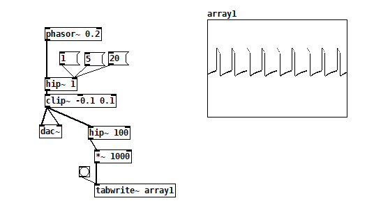
strange oscillation in [hip~ 1]
I noticed this oddity while using a [phasor~] at low frequencies to ping a resonant filter: [hip~] oscillates quietly for cutoff frequencies below 20. You also get an interesting "zing" when you step its input between DC levels.
hip~ 1 oscillation.pd
No biggie, just something weird I noticed. I bet the math behind it is interesting.
 posted in technical issues
Trying to reproduce a sound with Pd
@jameslo Analog components all have tolerances, +- 10% is not uncommon for pots, so any of the knobs between the two modules could be 20% off from each other given a worse case scenario, plus all those other components in the module could make it even further off, Generally circuits are designed to minimize the effects of component tolerances and high tolerance parts will be used in critical locations like frequency but amplitude and PW are not critical location, our ears will not notice small differences here. On top of that components age and their value changes, so two 30 year old modules can be very different despite once being identical. Things like phase and frequency are not constants in the analog world, things drift and oscillators which share a power source tend to sync when they get close. Most have to be very close in frequency to sync this way, the beat frequency will be well under 1hz but under certain situations you can hear it if you listen close. When trying to copy a patch from the analog world in the digital, knobs can only be used as a rough guide, need to use your ears.
When you distorted the wave you added harmonics and changed the strengths of the old harmonics, only harmonics of equal strength but opposite phase will cancel fully. You most likely did have cancellation just not full cancellation (depends on how you distorted it). Put both oscillators to the same frequency and opposite phase, listen to the distorted one and then add in the undistorted oscillator, you should hear a decrease in harmonic content from the cancellation. This will be most apparent with low to moderate levels of distortion, the more distortion, the more harmonics you are adding, the less the two waves have in common, and as a result less gets canceled.
Edit: didn't quite finish that last sentence.
 posted in patch~
additive sine-synth thing
I was watching some of miller's videos on the internals of pd and got inspired to try a different (probably processing intensive) method of parallel processing for multiple oscillators/additive synthesis & came up with this ugly thing after some hours. Basically it uses upsampling to use every "location" in a block as a separate oscillator. (so sample 2 in a block is oscillator 2, etc.) The subpatch is upsampled x64 with 64 block size so every sample 1 sample of 64 oscillators are being processed. [tabsend~] and [tabreceive~] are used for storing the phase of the sine waves in-between samples. It's probably relatively heavy on the processing. still I thought it was kinda cool.
If anyone knows how to get the sum of all samples in a block in vanilla that would also be helpful (I'm using [rfft~] now but don't need to do an entire fft just for the sum)
additive.pd
 posted in patch~
Synthesis OSC
@8v01d You are using only ring modulation. You can change by adding frequency modulation (it is very powerful and can create very interesting sounds) to some carrier oscillators but not all. Also you could split the output of each oscillator right before the envelope into 2 channels (one left and one right to have stereo). Then you could change the envelope to be different in the stereo section. Also you could use different kinds of oscillators (sine, triangle, saw, square etc.). You made it clear and i like that. Nice.
 posted in patch~