Arduino -> Pduino problem measuring lapsed time with [realtime]
I’m trying to measure the speed of a wheel to control a synth. I’m using an arduino and Pduino. There is bits of papers taped to the wheel and they pass through a photo interrupter module. It’s using the digital output. I’m using the realtime-object to measure the time between papers passing the interrupter.
My question is why my output from [realtime] looks like this:
print: 9.917
print: 20.032
print: 19.994
print: 10.03
print: 10.025
print: 20.043
print: 18.553
print: 11.467
print: 20.026
print: 20.007
print: 9.879
print: 20.018
print: 8.59
print: 21.44
print: 10.032
print: 20.017
print: 20.02
print: 10.034
print: 18.484
print: 21.428
print: 10.032
And so on…
The numbers are always close to a multiple of 10. I can’t find a single integer ending with 2, 3, 4, 5, 6, or 7. Since I can se the numbers directly from the arduino (in arduino IDE) I’m pretty sure it’s not a problem at the arduino or sensor end of things. The numbers there looks totally reasonable to me. So, what is going on with my patch or with Pduino that makes it look like this? I could add that when using the timer-object there is nothing but exact multiples of 10:s outputted.
Also the stream of numbers I get is way to inconsistent for my uses and jumps around a lot. As you can see in the patch attached I’m using two [moving-ave] to smooth it out to something near acceptable. Is there limitations to using Pduino or is this again something in my patch.
Fairly new to PD and arduino so I’m sure there is a lot a can do better. Any help is appreciated. Thanks!
Patch:
PduinoTest.pd
 posted in technical issues
converting arduino sketches to run in Pd for Bela
hello! this question intersects with Pd even if it is not about Pd specifically...
I currently have several (installation) pieces in which the sound is run from Pd and then I have motors or sensors being run off other things.
This means that in one case I am using a raspberry pi for the Pd part and an Arduino mega for the motor part
In another case I have Pd running on a Bela/BBB and then an Arduino doing the motor stuff.
The reason for this inefficiency is that my knowledge is fairly limited on these platforms. However, it is annoying to have to use the extra gear when I don't have to. Especially because I know that both the raspberry and the Bela have pins that could be used in place of the arduino for this purpose. Since the Bela is a simpler case and the pins can be addressed directly from Pure Data, I will ask about that and leave the Raspberry behind for now (as I think I would end up running Pd AND Arduino on that board anyway, whereas with Bela, one can easily address the pins from inside Pd without any other programs or libraries).
My question is this: does anyone know how the standard mappings of pins Analog/Digital/and PWM pins on the Arduino lines up on the Bela? Does the Bela have have PWM pins like, for example pins 8,9, 10,11 on Arduino Mega or Dueminanove? And if so, what is the best way to address them from Pure Data? Basically, I'd like to convert my already very simple Arduino sketches over to Pd, so that both motors and Audio can run from the same patch.
I know this isn't specifically a Pd issue but I have asked a related question on the Bela forum but didn't get an answer so I hoped someone might know or be able to suggest a resource over here...
I have traversed the Bela documentation already of course....and will continue with that meanwhile.
Jorge
 posted in I/O hardware diy
PIR+ARDUINO+PDUINO
Hi @David and @Alexandros, thank you so much for your help, it is really appreciated.
Alexandros : the arduino abstraction includes comport, here is the arduino object pd:
arduino.pd.zip
I have followed your advice and included the arduino object and print, but this still not working.
Also, when I click on print nothing happens.
Here is my patch:
PIR_Arduino_Puredata V2.pd
What am I missing?
Many thanks again for any help you might provide
 posted in I/O hardware diy
PIR+ARDUINO+PDUINO
Jumping in due to David's prompt. I don't use PDuino, but I checked both yours and David's version of your patch, and there's no [arduino] or [comport] object. So, how do you expect to communicate with the Arduino using Firmata, since you don't have these two? [comport] is used for serial communication with USB devices, and [arduino] takes care to translate the user-friendly messages, such as "pinMode 2 input" to bytes in the Firmata protocol. I think the [arduino] abstraction includes the [comport] object, so it takes care of that for you.
From what I understand, you have to send this "pinMode" message to the [arduino] abstraction, and you'll receive some output from it. Connect a [print] to it to see what you get.
 posted in I/O hardware diy
Comport in browser?
Hi! I'm stuck in a room with a Chromebook and an Arduino. I've got purrdata.glitch.me/ from @cuinjune working in one Chrome tab and Arduino IDE in another tab monitoring the serial input. What would be needed to get comport to read the serial port from the usb/arduino?
I guess the ultimate goal is: what is the lowest latency setup from an Arduino sensor into PD on a chromebook or browser only?
I don't necessarily need the Arduino environment running for my uses, it's just that it looks like it's running an agent that allows the site to access the usb. Thanks for any thoughts!
 posted in technical issues
Arduino->Pd with Open Sound Control
@jameslo Thanks a lot!
I can send messages locally between Pd, Processing and Unity. But not Arduino.
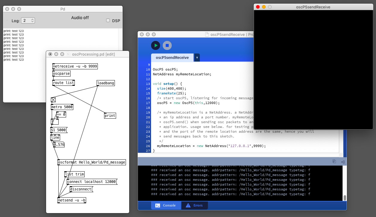
oscProcessing.pd
oscUnity.pd
oscP5sendReceive.pde
These works but I can still not for example replace Processing with Arduino.
@jameslo said in [Arduino->Pd with Open Sound Control] do you need bidirectional messaging? What data are you passing (if any)? What Arduino library would you prefer to use (I see there are more now than when I started)? is it over WiFi or ethernet or something else?
-bidirectional is good. Type of data, analog float, and digital. I have no preference for what library I use. I just want to make it work locally on a single computer.
I would like to use the Arduino as a controller for Pd through OSC.
For example, 5 analog ins on the Arduino that I after som treatment (smoothing and more) send locally to Pd, with custom osc addresses: /myArduino/analog-0
 posted in I/O hardware diy
Questions about Arduino, displays and communication with PD.
@jaffasplaffa I recently built my first device, a USB midi footswitch with an arduino. A bit of googling led me to the awesome MIDI Control Surface library.
The main thing to be careful about IMO is to get the right board to communicate directly over USB (Micro, Leonardo, Teensy, see the documentation), otherwise (Uno, Nano) you will need a serial-MIDI converter software like hairless (with GUI) or ttymidi (command line).
For the LED lighting I took inspiration from my other commercial controllers, and set the arduino's code to light up the LEDs by sending a notein and then it off with a noteoff (if you have multiple colors or blinking mode, you can use different velocities, e.g. 36 1 1 for solid green on button 36 (channel 1), 36 2 1 for blinking green, 36 3 1 for red, etc.
You can also hardcode the LEDs status with the buttons status, but you may loose flexibility (especially when using Pd, but it may be more complicated to use a DAW if you have to set up when to light up the LEDs, not sure).
Now I am looking into building another controller with faders and knobs, and there I'll indeed also need multiplexers, as I believe that the bigger Arduino I could find had ~40pins. You will probably need digital pins for the buttons and LEDs, while potentiometers need analog pins (as far as I could understand so far, but I'm also new to this!).
In any case, regardless of how you initially program the arduino (e.g. only notein/noteout to control the LEDs), you can just decide otherwise later on and reprogram it (just like you would update a commercial controller's firmware) to change the note numbers of each button, add special modes to give other functionalities to the same buttons, this kind of things.
Let me know how it goes ") I'm hoping to get started on mine in 2 weeks or so.
I'm hoping to get started on mine in 2 weeks or so.
 posted in I/O hardware diy
Having lots of switches into Pd
Here is the working Arduino code, (which is basically a straight copy from "project 8", but I wrote it while reading the tutorial)
// setup for 6 analog in och 12 digital in (pullup to be added).
//intended as experimental template. use pd patch
//made with tutorial Arduino for Pd'ers, project 8

byte myArray[25];

void setup()
{
  for(int i = 2; i < 14; i++)
  pinMode(i, INPUT);
  Serial.begin(9600);
}

void loop()
{
  myArray[0] = 0xc0;
  int index = 1;

  for(int i = 0; i < 6; i++){
    unsigned int knob = analogRead (i);
    myArray[index++] = knob & 0x007f;
    myArray[index++] = knob >> 7;
  }
  for(int i = 2; i < 14; i++)
  myArray[index++] = digitalRead(i);

  Serial.write(myArray, 25);
}
Then I tried to incorporate project 1 (blink):
// set a variable to hold the ledddddddz pin number
int led = 13;

void setup()
{
//  st pin 13 as output, to light up the LED
// whenever it is told so from Pd
pinMode(led, OUTPUT);
// start the serial communication o the Arduino
// and Pd can communicate with each other
Serial.begin(9600);
}

void loop()
{
 while(Serial.available()){
  byte ledState = Serial.read() - '0';
  digitalWrite(led, ledState);
 }
}
but when I tried to edit "blink" to work with several outputs and merge this in the project 8 code, I decided that I do not have enough understanding of the arduino code to pull it through. What is needed is, I think, another "for()" combined with digitalWrite() inside void loop()
Note: My plan now is to (still) use several Arduinos but with your code and abstractions (instead of the Pdunio). I will wait with the matrix switch setup since I have to take this in steps in order to have control of it.
This means that I am up and running, unless I want to use digital input and output from the same Arduino at the same time. I figure it would be great to have that sorted out beforehand so it works when I need it.
Thanks a lot.
posted in I/O hardware diy
pduino for Vanilla or how to control arduino outputs from PD
[arduino] is the Pduino abstraction that communicates with Arduino via Firmata, and I think it's vanilla. Any way, if all you want is to control Arduino pins from Pd, you just need to send the correct bytes to Arduino through [comport].
I've written a tutorial on the communication between Pd and Arduino which you can find here, under "Tutorials", it's called "Arduino for Pd'ers".
After I wrote the tutorial I also wrote some abstractions to facilitate this communication, which are not used in the tutorial. You can get them here. Though, these are meant to receive data from the Arduino, not send. Sending data is covered in the tutorial.
posted in technical issues
arduino consistent serial port number
@schoolshoes If it is possible then it will have to be done by the operating system (OSX). Maybe there is a utility that will help.
In windows the same port is always assigned, and then reserved, for the device. It is fixed by the system based on the serial number of the device.
But the Arduino has no serial number........ https://arduino.stackexchange.com/questions/11823/can-i-change-the-usb-device-name-of-arduino ....... and you would probably have to mess with its firmware.
It could be that re-plugging them in the correct order every time will be the only solution.
You might be able to buy / make some hardware to do that......?
David.
 posted in I/O hardware diy