Build a MIDI controller with the Arduino, Firmata and Pure Data
Time to start contributing some knowledge back to the wonderful world that is the internet; today, a step by step nice and easy tutorial on getting started to building your own MIDI controllers with the arduino.
When researching for my ableton controller project, I didn’t find much out there about using firmata on an arduino to send data to software. The standard approach just seemed to be create the code in the arduino language, upload it to your board and hack one of those MIDI to USB cables as a bodge job way of getting the MIDI out of the arduino.
So why firmata and pure data? Well the whole idea of firmata is that you flash it to your arduino, and it throws out serial about whats going on with the arduino inputs and outputs, then you decide how the software treats the readings coming in and going out.
Theory out the way, lets build some controllers. You’ll need a few things…
HARDWARE:
An arduino and something to wire into it (for this i’ll be using a pot)
A USB cable for your arduino
SOFTWARE:
Arduino – http://arduino.cc/en/Main/Software
Pure Data – http://puredata.info/downloads
Firmata – http://at.or.at/hans/pd/objects.html#pduino
Something to patch your new controller into; like Reason or Ableton Live
- SETTING UP FIRMATA AND PURE DATA
Install Pure Data and create a folder to store all your patches somewhere. Unzip Firmata and add the files ‘arduino.pd’, ‘arduino-test.pd’ and ‘arduino-help.pd’ to your new Pure Data folder. The ‘arduino.pd’ file is the object that we use in PD for opening up communication with your arduino and routing it to PD. Done? Awesome, your software is almost set up.
- FLASHING FIRMATA TO YOUR ARDUINO
Install the latest version of arduino and open it up. Connect your arduino with the USB cable to your laptop (i’m using a macbook for this by the way). In the example patches, open up “Standard Firmata”, select your board (im using an arduino mega), and your serial port (look for tty.usbserial for use with a USB cable). Then compile and hit the upload button and your arduino is now ready to use firmata and communicate with Pure Data!
- WIRING UP A POT
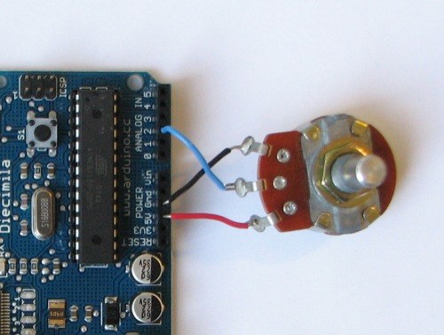
Potentiometers are cool, and theres a great arduino tutorial of how to wire one up here: http://www.arduino.cc/en/Tutorial/Potentiometer
Basically, all you need to know is that there are three pins; your two outer pins govern voltage flow across the pot, meaning one has to be 5V and the other has to be ground. It doesn’t matter which, but your 5v pin is going to be where your pot reads maximum, so convention dictates this should be the right hand pin. The center pin needs to be connected to an analog in on the arduino and will read the value of the pot as it sweeps from ground (0v) to 5v.
All wired up? Plug it into your laptop and open Pure Data, we’re ready to get things talking.
- SETTING UP OUR PATCH
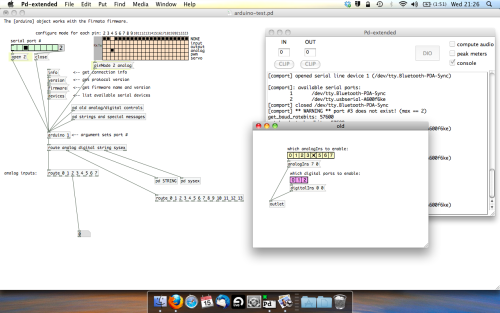
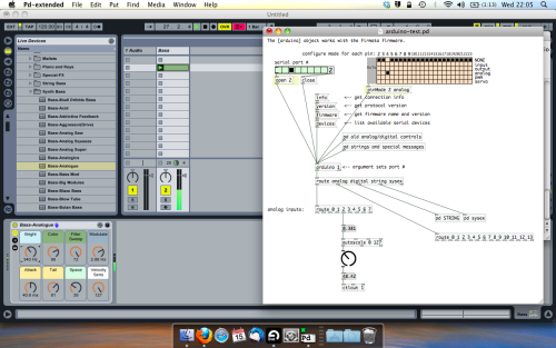
Open the example “arduino-test.pd” Pure Data patch you copied over earlier. It should look like this one…
The test patch has everything we need to open a connection and enable pins. Firstly, lets delete a bunch of stuff and make our window a bit bigger. Hit Command + E to enter edit mode in Pure Data.
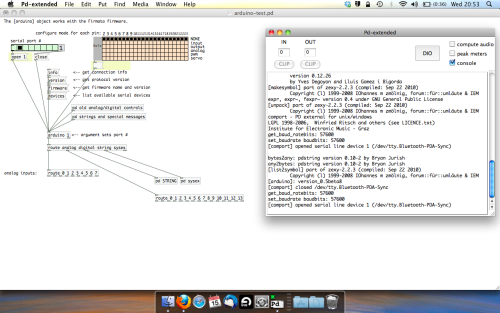
Ok a quick explaination; the key component here is the ‘arduino’ object. This is being drawn from the file you copied in earlier, and is what communicated with your arduino. Here we can do everything to control the arduino from opening a connection, to receiving data.
The large grid allows us to set the mode of each pin on the arduino. Remember pins 0 and 1 are reserved for Rx and Tx. I’m using analog pin 4 for this demo, so I’ve set my pin mode for pin 4 to ‘analog’.
Now we can plug our arduino in and get a reading from the potentiometer.
- ARDUINO INTO PURE DATA
With your arduino plugged in, hit command and E to bring us out of edit mode. In our patch, click on ‘Devices’ above the arduino object and open up the pure data terminal. (That other thing that loads with PD that has all the scary code in)
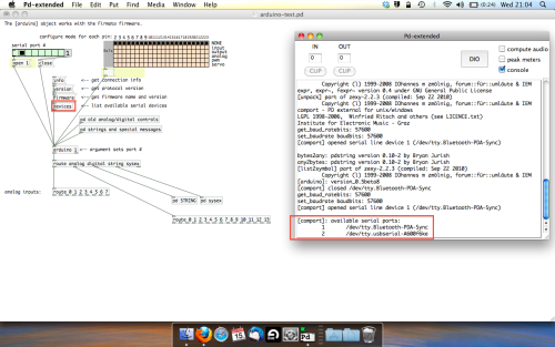
The “Devices” message connected to the arduino object pings your computer to find what devices are connected and on what serial ports. Since we’re using a USB cable to connect our arduino, we’re looking for something with ‘usbserial’ in it, in this case; port 2.
Select the relevent port in the green box at the top (remember the first box is ‘0’, second is ‘1’ and so forth) and hit ‘Open’ to establish a connection. Check the terminal to see if the connection was sucessful.

Now lets check we’re getting something in. Create a number box (Command + 3) and connect it to the relevent pin on the ‘Route analog’ box at the bottom. In this case, pin 4.
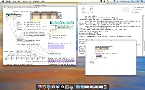
One more thing; if you’re not getting any readings in, you’ll need to click on ‘pd old analog/digital controls’ and enable your pins here too. What I tend to do in my patches is just not include the large grid but make my own ‘old pd’ controls custom to what i’m enabling/disabling to save space.
Here’s what the ‘old analog/digital controls’ subpatch looks like (pin 4 enabled)…
Come out of edit mode and check that you’ve got readings. If so congratulations! If not, troubleshoot, start with making sure your usb connection is opened, make sure all the correct pins are enabled (remember you’re counting from 0 not 1 on most of these buttons in PD, it’s just the way computers work).
- SCALING READINGS TO MIDI
So we’ve got a reading and chances are it’s to 3 decimal places between 0 to 1. No problem, create a new object (Command + 1) and type “autoscale 0 127”. This allows us to scale the input to a min and max value, in this case 0 to 127 of MIDI. Next, lets get things looking nice, create a new object and type “knob”. Connect this AFTER the autoscale object. (the knob is default set to read inputs from 0 to 127. Then create another number to display the scaled MIDI data coming out, and finally a new object and type “ctlout 1”.
It should look something like this…
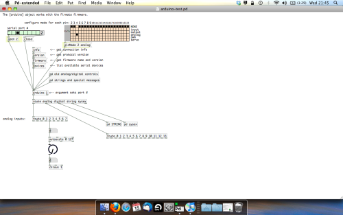
The second box should be outputing values from 0 – 127 now, and the knob giving a visual representation of your potentiometer.
Now lets patch it into ableton…
- PURE DATA TO ABLETON LIVE
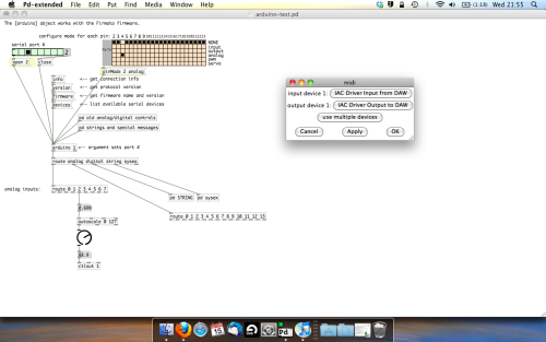
Firstly, you’ll need to set up your macs IAC driver if you’ve not done this. Basically you’ll need to go into Audio/MIDI preferences and enable your IAC driver. Then create a new input and output. One for input to DAW and one for output from DAW. Google around for a tutorial on this, its really simple, a 30 second job.
After you’ve set up your IAC driver, go back to PD and go to preferences > MIDI Settings, and connect your IAC driver.
Open ableton and go to its MIDI preferences. Create a device listing for your IAC driver and enable its ins and outs into ableton like so…
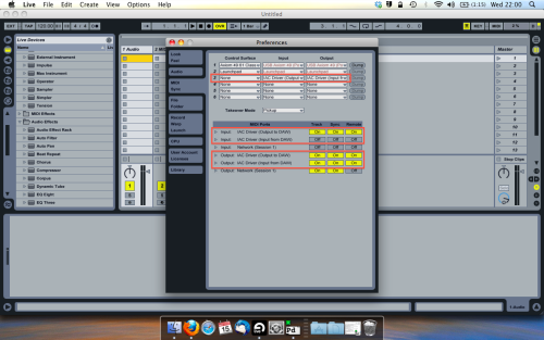
And thats it! Create an instrument and try to assign something! I’ve got it controlling the brightness of a bass sound here.
Shout out for Facu who requested this tutorial. Hopefully it’ll help some of you looking to get into this stuff and start building things but with no idea where to start.
 posted in tutorials
Issues uploading firmata for pduino
Hello all,
I'm working my way through the process for uploading firmata onto my arduino uno, using the Floss guide
(http://write.flossmanuals.net/pure-data/starting-pduino/)
I just downloaded the latest version of the arduino program from the arduino website, and then went through the process of deleting the old 'firmata' folder, and replacing it with the new one downloaded from: https://at.or.at/hans/pd/objects.html (running mac os 10.9,5).
However when I try and open the the arduino application, it comes up with an error that reads '"Arduino" is damaged and can't be opened. You should move it to the trash'."
I assume it has to be that specific Firmata in order to work with the Pduino objects? And is there any other way to upload it ? Or am I missing something obvious here?
I did think about rather than deleting the older firmata folder completely, just deleting the individual files and replacing them with those from the downloaded folder, but not sure if that's a good idea or not....
 posted in I/O hardware diy
Pduino + Arduino Output to Pins
Unfortunately, snapshot~ doesn't seem to send data at a rate which enables clean signaling of arduino pins. When it comes to audio anything, I find that outputting signal is necessary, as outputting control values just cannot keep up with audio. If you are looking to make a square wave generator that is controllable from puredata, the best way that I have found to do this is by using a combination of arduino, a DAC chip and an op-amp chip. Also, you'll want to use at least a 12 bit DAC, such as mcp4921 or mcp4725, as 8 bit DAC lacks the ability to tune the output fine enough to stay in tune with standard tuning. For opamp choices, you can pretty much take your pick. They all do pretty much the same thing, though you will find that every opamp has it's own unique sound quality. I really love the gritty sound of the CA313. A very good and popular sound for opamp VCO is the tl072 or tl075. There are tons of schematics out there for how to configure a square wave vco with opamps. You would just modify the components to fit the output of your DAC.
Next, you would send your controller values from PD to the arduino and have some code in the ar'dweener to handle communicating with the DAC. You can then add all sorts of fun stuff to your board like digipots, opamp buffers, VCAs and so on to make envelopes, LFOs etc.
If you don't want to track down additional chips (usually ordered from china being the only way to find them, cheap though they tend to be,) but want to have square waves being output directly from the arduino, then you would still be better off having pd send control values to the arduino and then let the arduino handle the signal generation to it's pins. For this purpose, you may want to look at the tone library or the mozzi library. Teensy boards have some expanded audio capabilities as well, but teensy boards are a bit expensive for my taste, as you can get a freakin raspberry pi with a full linux operating system on it for a fraction of what it costs. Still, teensies are great and extremely handy for these types of applications if you dont mind dropping some extra money. I try to build everything to work on cheap arduino clones just for financial and practicality sake.
I have code and patches that I have written to control these types of circuits for many DACs and digipots with SPI and I2C protocalls... let me know if you'd like to check them out for some guidance.
 posted in technical issues
Pduino + Arduino Output to Pins
Dear Forum,
Experienced PD user, intermediate Arduino user here.
My goal is to send several different frequency square waves (to be used as "on" and "off" signals for a circuit) to various output pins on an Arduino.
I am up and running using the Pduino library, and have PD and Arduino talking to each other.
However, I am not able to output audio-rate signals to any Arduino pins. For example, sending a square~ into an appropriately timed snapshot~ to output 0's and 1's to Arduino pins yields random clicking/sputtering Arduino output, rather than the expected steady square wave tone at any freq.
My arduinos play a square wave out through the pins just fine when using the Arduino IDE...so, what am I missing in the communication between Arduino and PD/Pduino? A speed issue?
Thanks in advance for any advice!
 posted in technical issues
Carriage return in messages from Pd to Arduino?
Hello. I'm working on an Arduino code and accompanying Pd patch, sending values from Pd to Arduino to control the PWM value sent to certain digital pins.
As of now, the code parses incoming strings in the format int,int and ends with a carriage return. This works just fine when sending the string from the Arduino software's own serial monitor, but I cannot seem to get it work when sending messages to the [comport] object. Right now I'm just using a single banged message box (ex. [3,80]) sent to [comport], so I suspect that I need to end the message with a carriage return in some format.
How would I go about doing this? I know \ is not allowed in Pd messages. What format does the Arduino understand in this situation? Ascii?
In the code below, I suppose I could change the string terminating character to something other than a carriage return, but I would be unsure of how to execute it properly.
I'm quite new to the Arduino platform, so if anything looks and sounds completely off, please do tell me.
void setup()
{
  Serial.begin(9600);

}

String command;

void loop()
{
 if (Serial.available() > 0)
 {
  char c = Serial.read();

  if(c == '\n')
  {
    parseCommand(command);
    command = "";
  }
  else
  {
    command += c;
  }
 }
}

void parseCommand(String com)
{
  String part1;
  String part2;

  //int SPACE int
  part1 = com.substring(0, com.indexOf(","));
  part2 = com.substring(com.indexOf(",") + 1);

  int pin = part1.toInt();
  int pwmval = part2.toInt();

  analogWrite(pin, pwmval);

}
Thank you.
 posted in I/O hardware diy
Dynamic Effect/Plugin Loader esp. For Rapsberry PI (DIY2 and Stamp Album effects/plugins)
Dynamic Effect Plugin Loader esp. For Rapsberry PI (DIY2 and Stamp Album effects/plugins)
DynamicEffectPluginLoaderForPI.zip
Background:
In the last couple of days I finally built something I have needed and wanted for a while (which later on I will discuss in more detail under a separate thread): an Arduino electric guitar.
In other words, I took the connections off the 5-way and knobs (internally connected to the pickups and line out) and rerouted the switch and knobs to an arduino. The reasoning being I can control Way more with pd and those knobs than what they were originally intended to do if I capture their output using Arduino.
However, the patch I had built for it was clocking in at about 275-300% of the pi's cpu. And while I could have gone back and added switches (which I took out a while back, to replace with fade-mixers for when I change an effect) throughout, the thought of doing that was more daunting than (considering how elaborate the patch is) I wanted to undertake.
Enter: Dynamic Patching.
I found that with just 3 straight-chained effects the pi ran at only about 10%.
So...here's what I built and am sharing now (before tying it into the arduino guitar, because I think others might want to go ahead and learn from it, extend it, expand upon it, use it, etc. etc.).
The patch(es, there are two, one laid out for the DIY2 plugins and one laid out for the Stamp Album ones, will probably consolidate them later, but other things are demanding my attention) is pretty straight forward:
(Dependency on the tof/menubutton, tof can be found via deken)
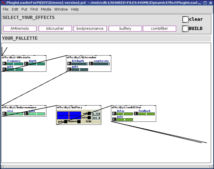
Click on the menus at the top to select an effect for each of the 5 slots or select the "unchanged" effect to leave that slot open.
Then click the BUILD bang or the CLEAR bang (to start over).
The selected effects will load into the PALLETTE subpatch already connected to adc~ and dac~.
That's really about all there is to it. Very straight-forward, clean, and very cpu light-weight. The racks of all 5 slots I tested ran at about 10-12% on my PI 3r2.
Hope you can make use of it. And would love to hear feedback.
For the future:
Add a hid-stomp controller to load preset racks (which you can send in via the tof/menubotton) to load racks on the fly;
Add a meta-level to send either hid, osc, or arduino commands to each of the loaded effects.
Merry Music to us, one and all.
Peace,
Scott
p.s. Oh! The arduino guitar: though it has no connected pickups it gets its audio signal from an (about) 1" piezo mic fun-tacked to the knob-well inside the guitar. Sounds great. Just pure guitar. The tone, texture, etc. come after the fact via the pd-side.
Ciao for now.
Wanna say: the real genius lies not in what I cobbled together, but the strength of will and purpose it took for the two original developers to make abstractions so completely consistent and thoroughly aligned. My highest regards to you both. Thank you, both, so very much, for helping to make my "job" so easy.
 posted in patch~
Getting DHT-22 sensor data to PD/PD-l2Ork RPi3
Hello, first post here as a PD newbie (but Max veteran) ")
I have managed to get PD working on my RPi3 (well that was easy as it is included in the Rasbian repository!!) and I am currently installing PD-l2Ork. I hate to ask stuff without having had a good stab at it myself already but I just wanted to ask for tips on getting sensor information into PD.
I am going to take part in Tiree Tech Wave in a couple of weeks and I want to make some kind of reactive bio feedback sample player, trying to scrub local weather data looks like it might be quite hard so I thought of doing something a little more micro scale and use something like the DHT-22 to get local ambient data and to influence a generative system that plays back samples from file.
I am fairly competant with Arduino style C and have done a little work in Python (but Python does give me a headache!!) - I have managed to get DHT-22 collecting and feeding back data on the RPi with Python and on the Arduino individually. I have no idea right now how to go about getting that data into PD...
The DHT-22 has a basic microprocessor on it that sends the collected ambient readings as words on a single wire data line, People have made nice Arduino and Python libraries already to handle that painlessly...
I have installed pd-comport and I have the impression the PD-l2Ork has some good included GPIO handling, I think that what I could do quite easily right now is bring an Arduino along as well and get the Arduino to handle all the DHT-22 stuff, and also react to the data - this could result in something like triggers activating on several GPIO pins, all easy stuff. But it would be nicer and I would learn more if I could send the actual numbers based on temperature and humidity to PD and do stuff there... I have no idea how easy that would be, in Max/MSP I would use the serial object to get data from the Arduino, and it's pretty easy to filter what you see at either end.
I guess another possible benefit of serial is perhaps using Bluetooth and having the sensor located more remotely.
Of course, it's probably totally unnecessary to use an Arduino and it can all be handled by the RPi but using Python makes my blood pressure go up 
Anyway, woops I have written an essay... any thoughts, tips or words of encouragement would be welcomed!
 posted in I/O hardware diy
PD, Arduino, pduino setup help.
As @whale-av said, you need to set the path to the [arduino] abstraction (mind, it's an abstraction not an object - meaning, it's a Pd patch opened as an object). The help patch of [arduino] works because it's in the same directory with the [arduino] abstraction itself. One way to load abstractions to a patch is the patch being in the same directory with these abstraction.
When you try to open [arduino] in another patch (that's not in the same directory with [arduino] itself), Pd doesn't know where to find this abstraction and fails to load it. Once you tell Pd where this is (either via Preferences -> Path..., or by using [declare -path /path/to/arduino_abstraction]) it will find it and load it.
 posted in I/O hardware diy
Multiple patches sending to the same Arduino / change block size?
I'm working on a project involving Pure Data and Arduino. The idea is to play an audio file while controlling a pump that breathes air into an aquarium, based on the envelope of the audio, so that the bubbles correspond to the voice that you hear in headphones.
My problem is, while it works perfectly with one aquarium (playing the audio file + controlling the pump), it's less precise, and sometimes completely off, when I'm adding the others.
Files : main.pd, aquarium.pd, arduino.pd
The logic of one aquarium is inside an abstraction, [aquarium], with the file, threshold, audio output and Arduino pin as creation arguments. Every instance of the abstraction is playing its own file into a given audio output, and sending messages to the Arduino ("turn on pump X" or "turn off pump X"). It works quite well for most of the aquariums, so I guess (hope) the fix must be simple.
I tried different ideas to limit the message flow but didn't quite succeed (hence the mess below the [dac~] object, this stuff is not used anymore).
I only recently thought about increasing block size, thinking that would reduce the number of messages sent to the Arduino. However using the audio settings, it didn't seem to change anything, and I'm not sure how to use the [block~] object. Do I have to send the audio output through an [outlet~] object? I guess that would mean each of my 9 [aquarium…] blocks would need to have 9 outlets going into a [dac~] object in my main patch, and that would be a big spaghetti plate
I'd be curious to know if any of you has ever encountered this kind of issue, or has an idea to fix it, either with block size, pure data magic or anything else…
Thanks!
 posted in technical issues
Having trouble with paths/libs using vanilla Pd-0.46-7-64bit.app (Mac).
Hello. I'm having some trouble trying to load zexy and iemlib into PD Vanilla 0.46-7. I had no problems compiling and installing cyclone from https://github.com/electrickery/pd-cyclone. It works fine. So I tried installing iemlib and zexy from https://github.com/iem-projects/pd-iem using their binaries but there's something wrong going on. When I turn on "verbose" under path preferences, PD seems to be looking for a file with the same name as the object I'm trying to use. Using [zexy/multiplex] in a patch gives:
tried ~/Library/Pd/zexy/multiplex.d_fat and failed
tried ~/Library/Pd/zexy/multiplex.pd_darwin and failed
tried ~/Library/Pd/zexy/multiplex/multiplex.d_fat and failed
But there's no multiplex.d_fat only zexy.d_fat. Same with iemlib, there's no dollarg.d_fat or dollarg.pd_darwin only iem_mp3.d_fat, iem_t3_lib.d_fat, iemlib1.d_fat, and iemlib2.d_fat. I'm guessing these files are where the externals were compiled in.
I tried using deken and iemlib installs the .pd_darwin files but I guess this is an older version(?) and zexy is still installing zexy.d_fat so I can't load its objects.
I also tried loading the lib "zexy/zexy" under startup preferences and it loads ok but then I get messages like:
warning: class 'abs~' overwritten; old one renamed 'abs~_aliased'
and I seem to loose namespace functionality, I can no longer refer to [zexy/multiplex] and need to use only [multiplex], which I guess is the correct behaviour.
How does PD know how to look for objects on files with different names?
Any advice?
This thread is marked as solved http://forum.pdpatchrepo.info/topic/9677/having-trouble-with-deken-plugin-and-zexy-library-solved and sounds like a similar problem but I haven't been successful.
I hope my english doesn't suck.
Thanks!
 posted in technical issues