[catch~]: Would like to set the name programmatically
@ingox said:
latency-tester right,
it's not. here some fixes:
[throw~] and [catch~] do bring some latency with them as far as i know...
It depends on the execution order, described in 3. G05 of Pd documentation.
Patching like this has no latency for your 2nd and 3d version, as for dyncatch~ and throw~ chatch~ and s~ r~.
But there is other trouble with the 2nd and 3d version:
Deleting by 'dynamic-mouse-clicks' doesn't work if I use Pd's zoom-in, as I usaually do.
This is a bug of Pd: it messes up the coordinates.
Same happens if I undo after moving an object, it reappears somewhere else...
@ddw_music said:
In SC, I can arrange mixer channels in the order source --> target
[...] looks like the only way to force order is using an explicit patch cable
Not sure, but I belive only the order of objects is important, and even msend~ v1 could have 0 latency, if it would care about creation order!? Even across multiple patches? Creation order = execution order ?
Edit: yes and no: it's the creation order of the whole chain ...
in latency-tester2.pd:
[pd latency-meter] is the first object, [pd click] comes later,
... so deleting the patch-cord between [pd s] [pd r] brings back block-latency.
 posted in technical issues
Having lots of switches into Pd
Thank you for replying and sorry if I am unclear. I will try to slow down a bit.
@alexandros said:
@cfry definitely not necessary to use two Arduinos. I can't really understand where your problem lies.
-The problem is that it does not work when I try to use an arbitrary combination of pins in different modes (Digital in, Digital out, Analog in, Analog out).
Another problem is that I have a hard time reading the code parts that are handling the conversion data in order to do the serial communication, although I understand the principle of it.
You didn't reply to my earlier question about the pinMode calls where you use INPUT_PULLUP on analog inputs. Is this really necessary?
-I assumed that the problem lied in void ()loop as a conflict between the output and input handling sections. And that pinMode calls in void setup() was not relevant in this case. That is why I did not answer that question directly.
Also, why not use the analog pins in an array like with the digital pins? It will save a lot of writing and it's less error prone.
-I was foreseeing that I may want to configure those pins individually, but I can set it up with a loop for now.
One thing you might want to consider is having the Arduino notify Pd when it's done sending all its data and that it's ready to receive. That could be done at the end of the loop() function like this:
Serial.print("done ");
Serial.println("bang");
And in Pd have a [r done] object which will output a bang. Use this bang to send data from Pd to the Arduino by unpacking a list with all the accumulated data, possibly with a [list-abs/list-drip].
I use this notification technique in my 3dPdModular system, but there's a LOT of data there and it was only necessary. Perhaps you could try it out.
-I will try that.
Since I consider this to be basically your code I assumed that you could easily just insert the code for both input and output in void loop() in a way that works and that would show me how to solve it. Then I would be able to do further explorations and it would be end of story.
I will digest this a bit and may start a new thread, since this one has slided from "Having lots of switches into Pd" to "having a working code template for communicating between Arduino and Pd using and an arbitrary mixture of pin modes".
Please let me know if this still does not make sense. Thank you so much!
 posted in I/O hardware diy
Just Another (Drum) Sequencer...SortOf, codename: Virgo
Just Another (Drum) Sequencer...SortOf, codename: Virgo
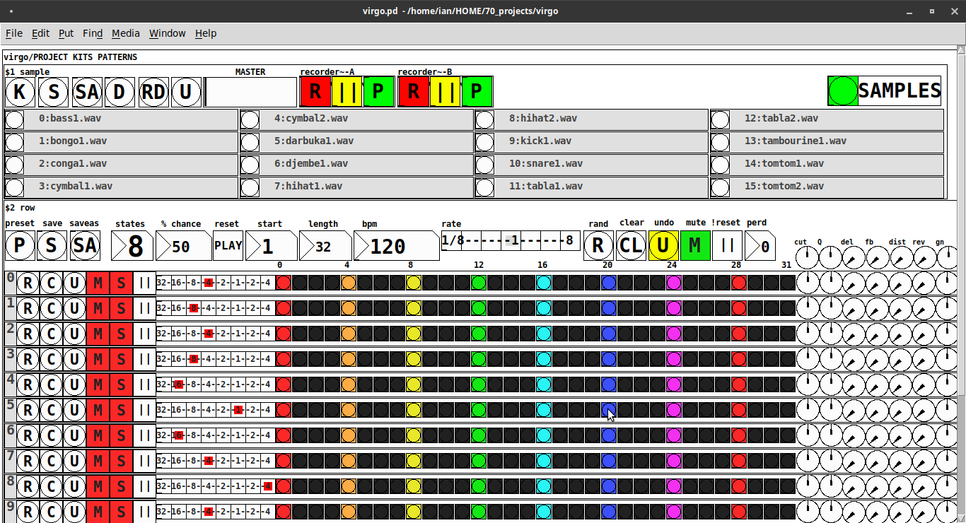
REQUIRES: zexy, moonlib, tof (as of Pd 0.50.2, all of which are in deken) and hcs (which comes by default with Pd 0.50.2 and is in deken (for extended))
Special Features
- Unique playhead per row; each with their own metro (beat)
- Up to 8 Volume states-per-beat (by clicking multiple times on the bang; where an rms=1 is divide among the states (2 states:0=rms=0(black), 1=rms=1(red); 3 states:rms=[0|0.5|1])
- Design approach: using creation arguments to alias abstractions, so subsequently they are referred to by their creation arguments, ex. in [KITS sample] sample is referred to as [$1]; which is how they are listed below)
(notes: what I learned experimenting with this design approach, I will share as a separate post. Currently, it does not include cut-copy-paste (of regions of the pattern)). I good way to start trying it out is clicking the "R" to get a random kit and a random pattern).
virgo:[virgo/PROJECT KITS PATTERNS]
- PROJECT[KITS PATTERNS]
- $1:[KITS sample]
- GUI
- K: openpanel to load a previously saved *.txt (text object) kit of samples; on loadbang the default.txt kit is loaded
- S: save the current set of samples to the most recently opened *.txt (kit) preset
- SA: saveas a *.txt of the current set of samples
- D: foldererpanel a sample directory to load the first (alphabetically) 16 samples into the 16 slots
- RD: load a random kit from the [text samples] object where the samples where previously loaded via the "SAMPLES" bang on the right
- U: undo; return to the previously opened or saved *.txt kit, so not the previously randomized
- MASTER: master gain
- (recorder~: of the total audio~ out)
- record
- ||: pause; either recording or play;
- play: output is combined with the sequencer output just before MASTER out to [dac~]
- SAMPLES: folderpanel to load a (recursive) directory of samples for generating random kits
- ABSTRACTIONS
- $1: sample
- bang: openpanel to locate and load a sample for a track
- canvas: filename of the opened sample; filenames are indexed in alignment with track indices in the PATTERNS section
- $1: sample
- GUI
- $2:[PATTERNS row]
- GUI
- P: openpanel to load a previously saved *.txt (pattern) preset file; on loadbang the default.txt pattern is loaded; the preset file includes the beat, pattern, and effect settings for the row
- S: save the current pattern to the most recently opened pattern .txt
- SA: save as (self-explanatory)
- states: the number of possible states [2..8] of each beat;
- %: weight; chance of a beat being randomized; not chance of what it will result in; ex. 100% implies all beats are randomized ; random beats result in a value)gain) between 1 and states-1
- PLAY(reset): play the pattern from "start" or on stop reset all playheads to start
- start: which beat to start the playheads on
- length: how many beats to play [+/-32]; if negative the playheads will play in reverse/from right to left
- bpm: beats-per-minute
- rate: to change the rate of play (ie metro times) by the listed factor for all playheads
- R: randomize the total pattern (incl period and beats, but not the effect settings; beats of 1/32 are not included in the possibilities)
- CL: clear, set all beats to "0", i.e. off
- U: undo random; return to the previously opened or saved preset, ie. not the previous random one
- M: mute all tracks; the playheads continue moving but audio does not come out of any track
- ||:pause all playheads; play will resume from that location when un-paused
- per: period; if 0=randomizes the period, >0 sets the period to be used for all beats
- Edit Mode
- Check the [E] to enter edit mode (to cut, copy, or paste selected regions of the pattern)
- Entering edit mode will pause the playing of the pattern
- Play, if doing so beforehand, will resume on leavng edit mode
- The top-left most beat of the pattern grid will be selected when first entering edit mode
- Single-click a beat to select the top-left corner of the region you wish to cut or copy
- Double-click a beat to select the bottom-right corner
- You may not double-click a beat "less than" the single-clicked (top-left) beat and vice-versa
- Click [CL] to clear your selection (i.e. start over)
- The selected region will turn to dark colors
- If only one beat is selected it will be the only one darkened
- Click the operation (bang) you wish to perform, either cut [CU] or copy [CP]
- Then, hold down the CTRL key and click the top-left corner of where you want to paste the region
- The clicked cell will turn white
- And click [P] to paste the region
- Cut and copied regions may both be pasted multiple times
- The difference being, cutting sets the values (gains) for the originating region to "0"
- Click [UN] to undo either the cut, copy, or paste operation
- Undoing cut will return the gains from 0s to their original value
- Check the [E] to enter edit mode (to cut, copy, or paste selected regions of the pattern)
- (effect settings applied to all tracks)
- co: vcf-cutoff
- Q: vcf-q
- del: delay-time
- fb: delay-feedback
- dist: distortion
- reverb
- gn: gain
- ABSTRACTIONS
- $1: [row (idx) b8] (()=a property not an abstraction)
- GUI
- (index): aligns with the track number in the KITS section
- R: randomize the row; same as above, but for the row
- C: clear the row, i.e. set all beats to 0
- U: undo the randomize; return to the originally opened one, ie. not the previous random one
- M: mute the row, so no audio plays, but the playhead continues to play
- S: solo the row
- (beat): unit of the beat(period); implying metro length (as calculated with the various other parameters);1/32,1/16,1/8, etc.
- (pattern): the pattern for the row; single-click on a beat from 0 to 8 times to increment the gain of that beat as a fraction of 1 rms, where resulting rms=value/states; black is rms=0; if all beats for a row =0 (are black) then the switch for that track is turned off; double-click it to decrement it
- (effects-per-row): same as above, but per-row, ex. first column is vcf-cutoff, second is vcf-q, etc.
- ABSTRACTIONS
- $1: b8 (properties:row column)
- 8-state bang: black, red, orange, yellow, green, light-blue, blue, purple; representing a fraction of rms(gain) for the beat
- $1: b8 (properties:row column)
- GUI
- $1: [row (idx) b8] (()=a property not an abstraction)
- GUI
- $1:[KITS sample]
Credits: The included drum samples are from: https://www.musicradar.com/news/sampleradar-494-free-essential-drum-kit-samples
p.s. Though I began working on cut-copy-paste, it began to pose a Huge challenge, so backed off, in order to query the community as to 1) its utility in the current state (w/o that) and 2) just how important including it really is.
p.p.s. Please, report any inconsistencies (between the instructions as listed and what it does) and/or bugs you may find, and I will try to get an update posted as soon as enough of those have collect.
Love and Peace through sharing,
Scott
 posted in patch~
sample and hold, [noise~] or random?
Thanks. I am back on this now. The project went well, but I would like to get it right anyway.
@lacuna said:
... and you can poll it every 64 samples only.
and why [noise~] with the output of [snapshot~] has no advantage over [random].
I basically understand the difference between audio and control signals, but it is hard to apply it practice. The sample and hold simulation random function is modifying held notes, that is why I assumed it could be mismatches. In this case it may be that the control signal is not applied to the audio object until the next DSP update (after 64 samples) so it will not be a problem. Right?
Is the random generated inside of the [clone]?
If not, something else might cause high CPU-load.
The random is generated outside of the clones, but the audio objects inside the clones is affected by the random signal, continuously.
The cheapest way to get random might not be calculating it in realtime, but reading preset random numbers from a text- or wavefile or an array with phasor~ or [f][+ 1]. But then the random set will loop.
I do not think I need the to be super efficient cpu-wise in this case, I just do not want to make any mistales that overload the engine.
But what can that error message be a sign of, then?
I attach my patch.
The FM synth part comes from this tutorial:
posted in technical issues
Pduino problem
Hello everyone, ive got this problem while trying to connect my arduino to Pd. Already installed firmata, used firmata test app to check its ok, and it is. But when i open the arduino-test pd patch, i get this:
netreceive: failed to sett SO_BROADCAST
comport - PD external for unix/windows
LGPL 1998-2015, Winfried Ritsch and others (see LICENSE.txt)
Institute for Electronic Music - Graz
[comport] Opening COM1
[comport]: could not open device COM1:
failure(2) ERROR_FILE_NOT_FOUND
[comport] opening serial port 1 failed!
moocow/string2any 32 -1
... couldn't create
route 13 0 20 1 (message->prepend) connection failed
route 14 0 20 1 (message->prepend) connection failed
route 16 0 20 1 (bang->prepend) connection failed
route 17 0 20 1 (bang->prepend) connection failed
moocow/string2any 32 -1
... couldn't create
moocow/any2string
... couldn't create
moocow/any2string
... couldn't create
moocow/string2any 32 -1
... couldn't create
[arduino]: version_0.5
[comport]: could not open device COM1:
failure(2) ERROR_FILE_NOT_FOUND
Firmware: 2-5.
UNKNOWN_INPUT_COMMAND: 0 480
UNKNOWN_INPUT_COMMAND: 0 479
UNKNOWN_INPUT_COMMAND: 0 479
UNKNOWN_INPUT_COMMAND: 0 480
UNKNOWN_INPUT_COMMAND: 0 479
UNKNOWN_INPUT_COMMAND: 0 480
UNKNOWN_INPUT_COMMAND: 0 479
UNKNOWN_INPUT_COMMAND: 0 479
UNKNOWN_INPUT_COMMAND: 0 479
UNKNOWN_INPUT_COMMAND: 0 480
UNKNOWN_INPUT_COMMAND: 0 479
UNKNOWN_INPUT_COMMAND: 0 480
So, i select the port im using and the A0 pin which is the one with the potentiometer im gonna use, and i get thousands of UNKNOWN_INPUT_COMMAND messages, i turn the pot and the values go from 0 to 1000, and the pd device info block has Firmata 2.5 so its recognizing the device, but cant go beyond that. Any ideas? I see that moocow is missing (and that could be relevant), but couldnt get anything using the "find externals" function.
 posted in technical issues
Digital to audio processing issues
@Joseph-Mikkelson No, changing the samplerate will not help, except that matching it to the soundcard reduces the load on the cpu......but there are more important issues...... see below.....
I should have expanded on latency.
Using a live input [adc~] and doing some Pd processing effects and then sending that to speakers [dac~] latency is not so much of a problem. Often it involves delays anyway (echo, reverb, etc.) and our ears are used to that.
Latency for playback of an audio track, or generated audio, is no problem...... it is heard when it arrives at the speakers and that is all.
Problems arise when the input goes straight to the output....... as with a monitor mixer built in Pd for example..... with live acoustic instruments...... where the musician hears their own instrument acoustically and the same sound delayed in the monitor. Essentially a chorus effect is produced, caused by the latency, and that will make it harder for a violinist for example to pitch correctly.
Chorus in a reverb effect really upsets violinists..... anything much over 5ms.
Of course a massive latency...... 100ms+..... will cause timing problems even for a guitarist, and even if they are the rare musician that didn't have such issues in the first place.
I have met classical and jazz musicians that have learnt to dissociate what they play from what they hear...... for example playing through a delay, but in sync with everyone else...... so playing say 1 second before everyone else....... but...... 
SAMPLE RATE
You should match your samplerate to your soundcard, or you will have re-sampling artefacts....... usually a low level high pitched whine when your patch is not producing any sound.
It is slightly more complicated than that.
If you play an audio file that was recorded at 44.1KHz while the Pd samplerate is set to 48KHz it will play back at the wrong speed....... Pd will not resample it and so the pitch will be wrong.
It's a PITA.
So the Pd samplerate must be set to match all the audio files that you use in Pd.
To avoid the artefacts you then need to set your soundcard to match Pd.
Other programs will adjust..... so that is not a problem.
External cards can make that change through their control panel, and internal cards should have the option somewhere.
In windows it is here in the speaker control panel..... https://forum.pdpatchrepo.info/topic/12094/newbie-clipping-on-pure-data-portable-with-mmio/4
and I am pretty sure that windows always sets the on-board soundcard to 48KHz "out of the box".
David.
 posted in technical issues
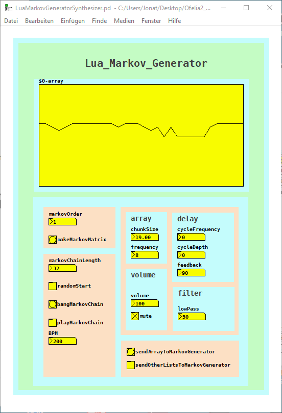
Lua / Ofelia Markov Generator Patch / Abstraction
I finished the Ofelia / Lua Markov Generator abstraction / patch.
The markov generator is part of two patches but can easily be used as an abstraction.
I want to use it for pattern variations of a sequencer for example.
It just needs a Pure Data list as input and outputs a markov chain of variable order and length.
Or draw into the array and submit it to the markov generator.
The first patch is an experiment trying to create interesting sounds with the markov algorithm.
In addition I used the variable Delay from the Pure Data help files:
LuaMarkovGeneratorSynthesizer.pd
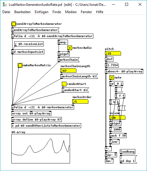
The second patch creates markov chains at audio rate, it is quite cpu heavy but works until the 10th markov order.
It is quite noisy but I was courius how it will sound:
LuaMarkovGeneratorAudioRate.pd
And here is the Lua code.
The core of the code is adapted from this python code: https://eli.thegreenplace.net/2018/elegant-python-code-for-a-markov-chain-text-generator/
A few things that I do not really understand yet, but finally it works without errors (it was not easy sometimes ") ):
):
-- LUA MARKOV GENERATOR;
function ofelia.list(fv);
;
math.randomseed(os.time()- os.clock() * 1000);
;
print("LUA MARKOV GENERATOR");
local markovOrder = fv[1];
print("Markov Order: ", math.floor(markovOrder));
;
-- make dictionary;
;
local function defaultdict(default_value_factory);
;
local t = {};
local metatable = {};
metatable.__index = function(t, key);
if not rawget(t, key) then;
rawset(t, key, default_value_factory(key));
end;
return rawget(t, key);
end;
return setmetatable(t, metatable);
end;
;
-- make markov matrix;
;
local model = defaultdict(function() return {} end);
local data = {};
for i = 1, #ofelia.markovInputList do;
data[i] = ofelia.markovInputList[i];
end;
print("Data Size: ", #ofelia.markovInputList);
for i = 1, markovOrder do;
table.insert(data, data[i]);
end;
for i = 1, #data - markovOrder do;
local state = table.concat({table.unpack(data, i, i + markovOrder - 1)}, "-");
local next = table.unpack(data, i + markovOrder, i + markovOrder);
model[state][next] = (model[state][next] or 0)+1;
end;
;
-- make tables from dict;
;
local keyTbl = {};
local nexTbl = {};
local prbTbl = {};
for key, value in pairs(model) do;
for k, v in pairs(value) do;
table.insert(keyTbl, key);
table.insert(nexTbl, k);
table.insert(prbTbl, v);
end;
end;
;
print("Key: ", table.unpack(keyTbl));
print("Nex: ", table.unpack(nexTbl));
print("Prb: ", table.unpack(prbTbl));
;
print("Make a Markov Chain...");
;
function ofelia.markovChain();
;
-- make start key;
;
local startKey = {};
if ofelia.randomStart == 1 then;
local randomKey = math.random(#keyTbl);
startKey = randomKey;
else;
startKey = 1;
end;
;
local markovString = keyTbl[startKey];
local out = {};
for match in string.gmatch(keyTbl[startKey], "[^-]+") do;
table.insert(out, match);
end;
;
-- make markov chain;
;
for i = 1, ofelia.markovChainLength do;
;
-- weighted random choices;
;
local choices = {};
local weights = {};
for j = 1, #keyTbl do;
if markovString == keyTbl[j] then;
table.insert(choices, nexTbl[j]);
table.insert(weights, prbTbl[j]);
end;
end;
;
-- print ("choices:", table.unpack(choices));
-- print ("weights:", table.unpack(weights));
;
local totalWeight = 0;
for _, weight in pairs(weights) do;
totalWeight = totalWeight + weight;
end;
rand = math.random() * totalWeight;
local choice = nil;
for i, weight in pairs(weights) do;
if rand < weight then;
choice = choices[i];
break;
else;
rand = rand - weight;
end;
end;
;
if math.type(choice) == "integer" then;
choice = choice * (1.0);
end;
;
table.insert(out, choice);
local lastStep = {table.unpack(out, #out - (markovOrder-1), #out)};
markovString = table.concat(lastStep, "-");
end;
;
return {table.unpack(out, markovOrder + 1, #out)};
end;
end;
;
 posted in patch~
lua markov generator
i build a lua markov generator inspired from this python code with the idea to use it with pure data / ofelia: https://eli.thegreenplace.net/2018/elegant-python-code-for-a-markov-chain-text-generator/
finally the code works fine with the eclipse lua ide or with this ide https://studio.zerobrane.com/, but somehow not yet with pure data / ofelia.
here is the (not yet working) patch: ofelia_markov.pd
and here the lua code: markov_pd.lua
math.randomseed(os.time()- os.clock() * 1000);
-- make dictionary;
function defaultdict(default_value_factory);
local t = {};
local metatable = {};
metatable.__index = function(t, key);
if not rawget(t, key) then;
rawset(t, key, default_value_factory(key));
end;
return rawget(t, key);
end;
return setmetatable(t, metatable);
end;
;
;
-- make markov matrix;
print('Learning model...')
;
STATE_LEN = 3;
print ("markov order: " , STATE_LEN)
model = defaultdict(function() return {} end)
data = "00001111010100700111101010000005000700111111177111111";
datasize = #data;
print("data: ", data);
print("datasize: ", #data);
data = data .. data:sub(1, STATE_LEN);
print("altered data: ", data);
print("altered datasize: ", #data);
for i = 1, (#data - STATE_LEN) do;
state = data:sub(i, i + STATE_LEN-1);
-- print("state: ", state)
local next = data:sub(i + STATE_LEN, i + STATE_LEN);
-- print("next: ", next);
model[state][next] = (model[state][next] or 0)+1;
end;
;
;
-- make markov chain;
print('Sampling...');
;
local keyTbl = {};
local nexTbl = {};
local prbTbl = {};
for key, value in pairs(model) do;
for k, v in pairs(value) do;
table.insert(keyTbl, key);
table.insert(nexTbl, k);
table.insert(prbTbl, v);
end;
end;
print ("keyTbl: ", table.unpack(keyTbl));
print ("nexTbl: ", table.unpack(nexTbl));
print ("prbTbl: ", table.unpack(prbTbl));
;
;
-- make random key;
local randomKey = keyTbl[math.random(#keyTbl)];
state = randomKey;
print("RandomKey: ", randomKey);
;
-- make table from random key;
local str = state;
local stateTable = {};
for i = 1, #str do;
stateTable[i] = str:sub(i, i);
end;
;
out = stateTable;
print ("random key as table: ", table.unpack(out));
;
-- make markov chain;
for i = 1, datasize do;
;
-- weighted random choices;
local choices = {};
local weights = {};
for j = 1, #keyTbl do;
if state == keyTbl[j] then;
table.insert(choices, nexTbl[j]);
table.insert(weights, prbTbl[j]);
end;
end;
-- print ("choices:",table.unpack(choices));
-- print ("weights:",table.unpack(weights));
;
local totalWeight = 0;
for _, weight in pairs(weights) do;
totalWeight = totalWeight + weight;
end;
rand = math.random() * totalWeight;
local choice = nil;
for i, weight in pairs(weights) do;
if rand < weight then;
choice = choices[i];
choice = choice:sub(1,1);
break;
else;
rand = rand - weight;
end;
end;
;
table.insert(out, choice);
state = string.sub(state, 2, #state) .. out[#out];
-- print("choice", choice);
-- print ("state", state);
end;
;
print("markov chain: ", table.concat(out));
somehow pure data / ofelia interprets the nexTbl values as a functions while they are strings?
this is part of what the pure data console prints: nexTbl: function: 0000000003B9BF30 function: 0000000003B9BF30 function: 0000000003B9BF30 function: 0000000003B9BF30 function: 0000000003B9BF30 function: 0000000003B9BF30 function: 0000000003B9BF30 function: 0000000003B9BF30 function: 0000000003B9BF30 function: 0000000003B9BF30 function: 0000000003B9BF30 function: 0000000003B9BF30 function: 0000000003B9BF30 function: 0000000003B9BF30 function: 0000000003B9BF30
ofelia: [string "package.preload['#d41b70'] = nil package.load..."]:93: attempt to index a function value (local 'choice')
and this ist the output from the lua ide:
Program 'lua.exe' started in 'C:\Users\Jonat\Downloads\ZeroBraneStudio\myprograms' (pid: 220).
Learning model...
markov order:   1
data:   00001111010100700111101010000005000700111111177111111
datasize:   53
altered data:   000011110101007001111010100000050007001111111771111110
altered datasize:   54
Sampling...
keyTbl:     5   7   7   7   1   1   1   0   0   0   0
nexTbl:     0   0   1   7   7   1   0   5   7   1   0
prbTbl:     1   2   1   1   1   17  7   1   2   7   13
RandomKey:  1
random key as table:    1
markov chain:   111111000077701111100070001100000001100017011171111117
Program completed in 0.06 seconds (pid: 220).
Build a MIDI controller with the Arduino, Firmata and Pure Data
Time to start contributing some knowledge back to the wonderful world that is the internet; today, a step by step nice and easy tutorial on getting started to building your own MIDI controllers with the arduino.
When researching for my ableton controller project, I didn’t find much out there about using firmata on an arduino to send data to software. The standard approach just seemed to be create the code in the arduino language, upload it to your board and hack one of those MIDI to USB cables as a bodge job way of getting the MIDI out of the arduino.
So why firmata and pure data? Well the whole idea of firmata is that you flash it to your arduino, and it throws out serial about whats going on with the arduino inputs and outputs, then you decide how the software treats the readings coming in and going out.
Theory out the way, lets build some controllers. You’ll need a few things…
HARDWARE:
An arduino and something to wire into it (for this i’ll be using a pot)
A USB cable for your arduino
SOFTWARE:
Arduino – http://arduino.cc/en/Main/Software
Pure Data – http://puredata.info/downloads
Firmata – http://at.or.at/hans/pd/objects.html#pduino
Something to patch your new controller into; like Reason or Ableton Live
- SETTING UP FIRMATA AND PURE DATA
Install Pure Data and create a folder to store all your patches somewhere. Unzip Firmata and add the files ‘arduino.pd’, ‘arduino-test.pd’ and ‘arduino-help.pd’ to your new Pure Data folder. The ‘arduino.pd’ file is the object that we use in PD for opening up communication with your arduino and routing it to PD. Done? Awesome, your software is almost set up.
- FLASHING FIRMATA TO YOUR ARDUINO
Install the latest version of arduino and open it up. Connect your arduino with the USB cable to your laptop (i’m using a macbook for this by the way). In the example patches, open up “Standard Firmata”, select your board (im using an arduino mega), and your serial port (look for tty.usbserial for use with a USB cable). Then compile and hit the upload button and your arduino is now ready to use firmata and communicate with Pure Data!
- WIRING UP A POT
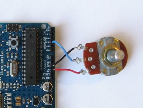
Potentiometers are cool, and theres a great arduino tutorial of how to wire one up here: http://www.arduino.cc/en/Tutorial/Potentiometer
Basically, all you need to know is that there are three pins; your two outer pins govern voltage flow across the pot, meaning one has to be 5V and the other has to be ground. It doesn’t matter which, but your 5v pin is going to be where your pot reads maximum, so convention dictates this should be the right hand pin. The center pin needs to be connected to an analog in on the arduino and will read the value of the pot as it sweeps from ground (0v) to 5v.
All wired up? Plug it into your laptop and open Pure Data, we’re ready to get things talking.
- SETTING UP OUR PATCH
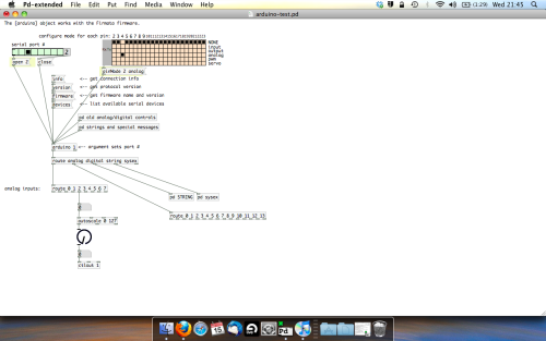
Open the example “arduino-test.pd” Pure Data patch you copied over earlier. It should look like this one…
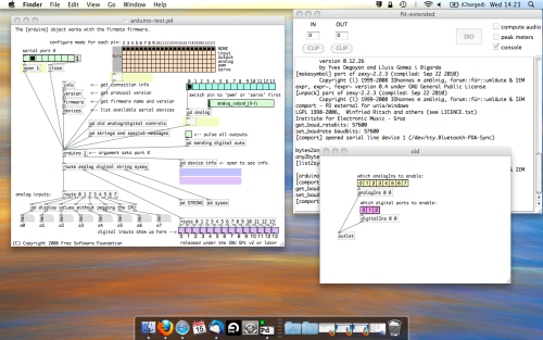
The test patch has everything we need to open a connection and enable pins. Firstly, lets delete a bunch of stuff and make our window a bit bigger. Hit Command + E to enter edit mode in Pure Data.
Ok a quick explaination; the key component here is the ‘arduino’ object. This is being drawn from the file you copied in earlier, and is what communicated with your arduino. Here we can do everything to control the arduino from opening a connection, to receiving data.
The large grid allows us to set the mode of each pin on the arduino. Remember pins 0 and 1 are reserved for Rx and Tx. I’m using analog pin 4 for this demo, so I’ve set my pin mode for pin 4 to ‘analog’.
Now we can plug our arduino in and get a reading from the potentiometer.
- ARDUINO INTO PURE DATA
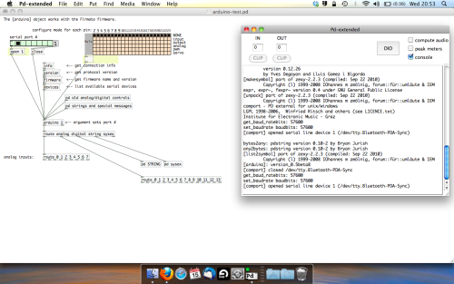
With your arduino plugged in, hit command and E to bring us out of edit mode. In our patch, click on ‘Devices’ above the arduino object and open up the pure data terminal. (That other thing that loads with PD that has all the scary code in)
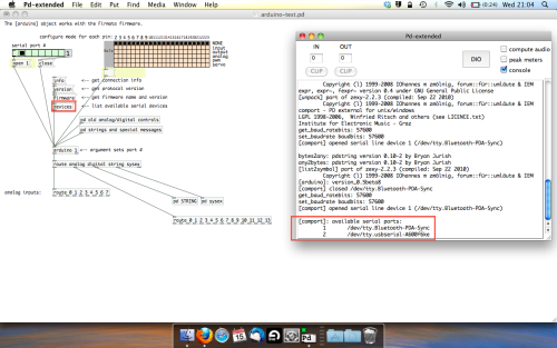
The “Devices” message connected to the arduino object pings your computer to find what devices are connected and on what serial ports. Since we’re using a USB cable to connect our arduino, we’re looking for something with ‘usbserial’ in it, in this case; port 2.
Select the relevent port in the green box at the top (remember the first box is ‘0’, second is ‘1’ and so forth) and hit ‘Open’ to establish a connection. Check the terminal to see if the connection was sucessful.

Now lets check we’re getting something in. Create a number box (Command + 3) and connect it to the relevent pin on the ‘Route analog’ box at the bottom. In this case, pin 4.
One more thing; if you’re not getting any readings in, you’ll need to click on ‘pd old analog/digital controls’ and enable your pins here too. What I tend to do in my patches is just not include the large grid but make my own ‘old pd’ controls custom to what i’m enabling/disabling to save space.
Here’s what the ‘old analog/digital controls’ subpatch looks like (pin 4 enabled)…
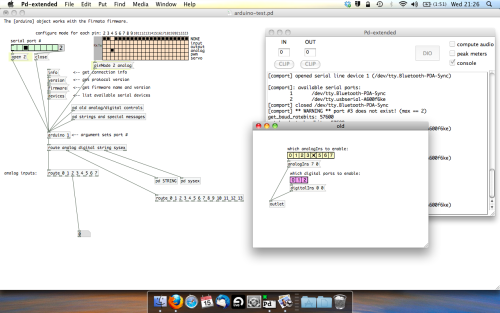
Come out of edit mode and check that you’ve got readings. If so congratulations! If not, troubleshoot, start with making sure your usb connection is opened, make sure all the correct pins are enabled (remember you’re counting from 0 not 1 on most of these buttons in PD, it’s just the way computers work).
- SCALING READINGS TO MIDI
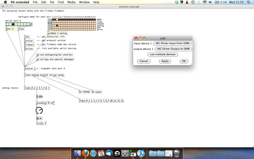
So we’ve got a reading and chances are it’s to 3 decimal places between 0 to 1. No problem, create a new object (Command + 1) and type “autoscale 0 127”. This allows us to scale the input to a min and max value, in this case 0 to 127 of MIDI. Next, lets get things looking nice, create a new object and type “knob”. Connect this AFTER the autoscale object. (the knob is default set to read inputs from 0 to 127. Then create another number to display the scaled MIDI data coming out, and finally a new object and type “ctlout 1”.
It should look something like this…
The second box should be outputing values from 0 – 127 now, and the knob giving a visual representation of your potentiometer.
Now lets patch it into ableton…
- PURE DATA TO ABLETON LIVE
Firstly, you’ll need to set up your macs IAC driver if you’ve not done this. Basically you’ll need to go into Audio/MIDI preferences and enable your IAC driver. Then create a new input and output. One for input to DAW and one for output from DAW. Google around for a tutorial on this, its really simple, a 30 second job.
After you’ve set up your IAC driver, go back to PD and go to preferences > MIDI Settings, and connect your IAC driver.
Open ableton and go to its MIDI preferences. Create a device listing for your IAC driver and enable its ins and outs into ableton like so…
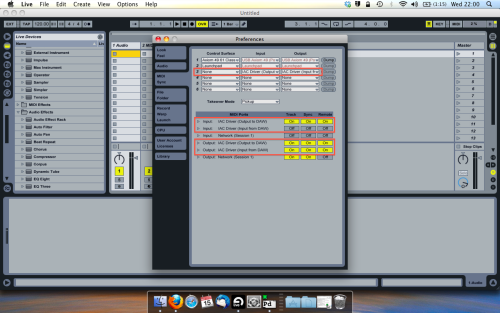
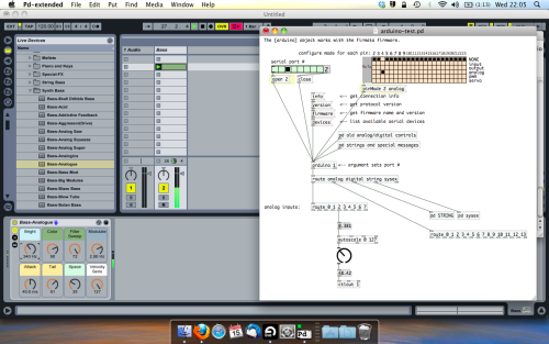
And thats it! Create an instrument and try to assign something! I’ve got it controlling the brightness of a bass sound here.
Shout out for Facu who requested this tutorial. Hopefully it’ll help some of you looking to get into this stuff and start building things but with no idea where to start.
 posted in tutorials
Can the stack overflow error affect the result of a random number generator?
@deframmentazione-geometrica And then it depends whether you are looking for the correct distribution (chance for each and every value) in which case a PRNG is the way to go. What meaning are you giving to the word "random"?
A PRNG is seeded, and deterministic, and like the uncertainty principle......... you know that every value will occur.... but not when it will occur (well... you do, but you will not remember!).
I messed around with this a bit........ true random.zip
[truish-random] sets the seed for [random] as the patch is loaded..... according to the computer time.
This avoids the "problem" that [random] gives the same sequence at every new start because it is "seeded" by $0 (probably). [random] is a series, "played" according to the seed.
[true-random] uses the [noise~] object. This is still deterministic, probably preserves the distribution, but it will be hard for a human to spot any pattern.
You could mix in some background noise from your computer microphone. That would be considerably less deterministic (lets not discuss the universe) but ruin "equal chance" in the human time frame.
David.
posted in technical issues