Lower limit to phasor~ frequency?
@yannseznec there is a limit in precision for any finite numerical representation. However, for floating point that becomes more complicated to calculate. The relevant code is
x->x_biginc = (x->x_target - x->x_value)/(t_float)nticks;
x->x_inc = x->x_1overn * x->x_biginc;
and in the dsp function:
x->x_1overn = 1./sp[0]->s_n;
so the inc will be (target value - current value)/(total time in samples). Time in samples will be rounded to the block size. I believe whether or not this number will increment the line~ depends on how big or small the current value of the line~ is. (again, it's complicated since it's floating point).
for instance if the current value of line~ is 1 then inc would have to be less than 2^-24 to not be able to increment I think. this would correspond to going from 1 to 2 over 16777216 samples, or ~6 minutes 20 seconds @ 44100 samplerate. (so you couldn't go from 1 to 2 any slower than that and have it represent the correct values within the block). Every time the value of line~ doubles so does the smallest representable increment.
however, line~ also uses the biginc variable, which means that after every block it will be able to update using a bigger increment. This means that line~ will still be able to increment up to blocksize times more than that calculation ^ after every block, though values inside every block would be the same. (so ~6 hours 46 minutes @ blocksize 64 according the above calculation I think)
if going from 0 to 1 all of those values would be doubled (it could represent increments corresponding to twice that time, bounded by the lowest representable increment that corresponds to going from 0.5 to 1)
there are other considerations of precision as well. If the increment can only be represented with a certain number of binary digits when added to the current value then there will be round-off errors in the values generated. (but if you need values of that precision you would have round-off errors somewhere else anyways probably)
another numerical bound on the use of line~ is the use of an int to represent ticksleft. If we assume this is a 32-bit signed integer then there can only be 2,147,483,647 blocks, which is ~36 days @ 44100 samplerate and a blocksize of 64. (this would be longer than whatever limitation the floating-point would impose tho I think)
this is all assuming that the size pd uses for samples and floats are 32-bit floating point. If pd is compiled to use 64-bit doubles instead then all of those values would be 2^29 times longer
edit: actually, looking at the code vline~ does use doubles for everything, so if you need really long ramps you should have no problem if you use vline~ instead of line~, even in normal non-double pd. It would take a time longer than 6,472 years for a vline~ going from 1 to 2 to stop being able to increment within a block of 64 samples @ 44.1k. (and a time of 414216 years to stop incrementing at all across blocks)
In the case of vline~ the bounding factor of precision might be in the representation of time actually since it doesn't use ticksleft
edit 2: it couldn't represent incrementing ~1.45 ms which is the time for a block of 64 @ 44100 samples if the current time were ~ 2^53 ms, which would be 9007199254740992, or 285,421 years before stopping to work completely.
long story short: you should be able to use vline~ (but not line~) for ramps of at least a few years long (depending on the range of its values) before it stops incrementing within a block. For the specific case of going from 0 to 1 @ 44.1k, you should be able to run a vline~ for ~129,000 years before it stops incrementing within a block (though it would still increment between blocks)
 posted in technical issues
[writesf~] problem
A couple of illustrations.
Let's say we want a sine wave covering 16.5 samples. To illustrate, I used SuperCollider to put two sine wave cycles into 33 samples.
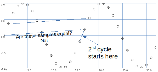
The second cycle begins when the wave crosses the 0 line in the middle.
This is between samples.
So, the second cycle must be represented by sample values that are different from the sample values for the first cycle.
That is, it is possible to have that zero crossing between samples -- but the sampling process produces different values.
Let's look at it a different way: blue samples = one sine wave cycle covering 33 samples; green samples = 2 cycles in 33 samples.
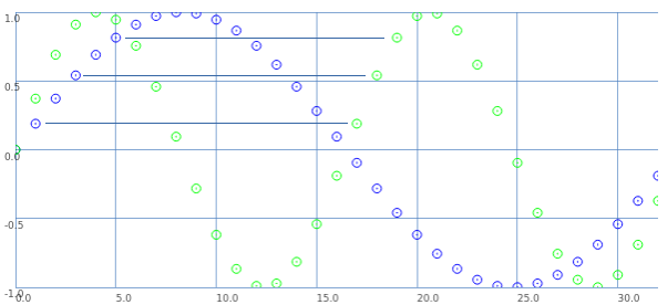
If we start counting samples at 0:
- Blue 0 = Green 0.
- Blue 2 = Green 1.
- Blue 4 = Green 2. etc.
That is: read through the blue samples at double speed, and you get the 16.5 wavelength. (This is exactly what David said.)
What about the second cycle starting at 16.5?
- Blue 1 = Green 17.
- Blue 3 = Green 18. etc.
These are the sample values that were skipped the first time.
So, Green 17 (the first concrete sample value after the second cycle begins) is the value in between Green 0 and Green 1. Green 18 is in between Green 1 and Green 2.
This is interpolation.
Interpolation is the mathematically correct way to represent fractional cycles in a sampled signal.
You can try to say that this "isn't the real problem," but... this is the problem, and interpolation is the solution.
hjh
 posted in technical issues
Phase modulation FM8 emulation troubles
@RandLaneFly "When the mod index is maxed out it sounds way more extreme and than on the FM8."
Without looking at your patch --
I've always done FM (leaving PM aside for a moment) such that index = 1 means that, if f is the main frequency, the carrier frequency oscillates between 0 and 2f.
mod_phase = phasor(0 .. 2pi) at (f * ratio) Hz

mod = sin(mod_phase) * index

car_phase = phasor(0 .. 2pi) at (f + (f * mod)) Hz = (f * (1 + mod)) Hz

carrier = sin(car_phase)
If you do phase modulation like this, then index has exactly the same meaning.
mod_phase = phasor(0 .. 2pi) at (f * ratio) Hz

mod = sin(mod_phase) * index

car_phase = mod + phasor(0 .. 2pi) at f Hz

carrier = sin(car_phase)
Takeaway: if the phasor goes 0 to 2pi, then you don't need to do any extra scaling on the modulation index for PM and FM to be compatible.
The catch in Pure Data is that the phasor is not 0 to 2pi. It's 0 to 1.
So, for phase modulation, you have to scale the index down by 2pi: mod --> [/ 6.28319].
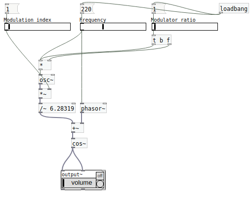
hjh
posted in technical issues
has anyone done any work on emulating (nautical) breaking waves?
my current thinking is...
for the static version of just sound cresting use 3 wave tables assembled with the 3 shapes representated below (sin(x=0 to 3/2pi), sin(x=(pi to 3/2pi)/2offset pi), and sin(x=pi-2pi).
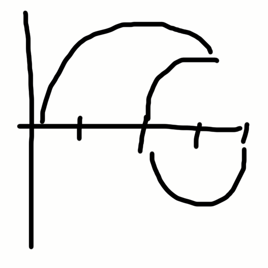
as to whether this will auditorially speaking result in 0, I am unconcerned, i.e. just sum them and see what it sounds like/is it discernibly different from just osc.
if someone, can tell me how to get those wave tables, that would be great. thanks, in advance.
note: also found this:
http://teachersinstitute.yale.edu/curriculum/units/2008/5/08.05.06.x.html
which may lead us to a possible Dynamic osc~ of breaking-wave form, since I am pretty sure we can do this using [osc~] plus some fancy audio arithmetic, ex. a timer to [*~ 0] where any of the 3 forms are not present, etc.
thanks, also for any and all thought put into it.
just stumps me, why on one hand Nature makes perfect osc sound but does not do the same thing for liquids (matter?).
peace and love. may your day be blessed.
-s
 posted in technical issues
16 parameters for 1 voice, continued...
@whale-av I love it how the post is named "16 parameters for one voice" and ended up in the extreme...hahah, 1_vod_12_2560 is pretty neat, sounds a lot like an organ, and yes the end is pretty interesting, hearing the different patterns of the sine waves. it would be nice to play with their intensities while there are no curves left, to see how different timbres are formed, i dont think exclusion is the way but rather integrating everything, a time for curves then those curves could sit still, the glissandi, then microtonal, its the best.
but what do you mean a curve for each sine? that would be a lot of curves, wouldnt it be better for one curve to control all their intensities? like the way you had done: each sine with a graph and only one curve controlling their position on the graph(maybe a graph generator to generate for each sine a graph, or for example: 2000 graphs to be followed by all the sine waves). or like the way we did way back when forming a list to pass through combinations of the sine´s volumes.
BtW, vod_13_20480 and vod_14_50960 didnt work, i just heard sometimes like glitchy noise, like a "popping".
 posted in technical issues
16 parameters for 1 voice, continued...
@H.H.-Alejandro Hello Ale.
Not finished....... just for testing..... Ale4.zip
All effects and audio meters etc. removed...... and only the first 2560 sines have micro adjustment.
In 1_vod_12_2560 it takes curves 3 to 18.
When running iannix I seem to get some distortion...... but if I stop sending the curves from iannix it is better.
This suggests that the messages are interfering with the audio..... but I am not sure...... in fact I think not....... something else.... maybe high frequency beating.
When you stop iannix....... or it gets to the end of the curves.... you can hear the beating at different rates of the sine waves....... it is interesting..... but starting the curves again makes it less audible.
Maybe massive sines controlled by curves are less interesting than massive sines on their own?
I will build one with only one curve for every sine..... to hear what Pieter suurmond expected..... so with a fixed note.
vod_13_20480 and vod_14_50960 are there for you to try..... (20480 sines and 50960 sines).
They take a while to load...... and for me they just distort..... but they really are a massive "ask" of the computer.
As I said above they are not finished. A lot of work needs to be done for all the curves to be used....... and as I think they will not work I have not done the work yet.
I really like 1_vod_12_2560 when iannix stops...... it is endlessly changing and interesting......
David.
 posted in technical issues
Multislider algorhytmic melodies
This melody is a combination of this expression: [expr $f1*(($f1>>$f2|$f1>>$f3)&$f4&$f1>>$f5)] and that expression: [expr sin(23.14159$f1/64)$f2+sin(43.14159*$f1/64)$f3+sin(83.14159*$f1/64 )$f4+sin(163.14159*$f1/64 )$f5+sin(323.14159*$f1/64 )*$f6] (more or less the sinesum message). Its one circle of a loop with 512 steps (8x64 step):
 posted in output~
Weird crest of first wavelength when summing bandpass filter outputs
band pass filters are kind of like exponentially dampened sine waves. keeping this in mind, try recording 4 sine waves of equal amplitudes added at those exact frequencies and look at the waveform, it's very similar. It's just a result of adding those frequencies together
in this case it is a phase issue because the band pass filters all have the same kind of phase response, and when the frequencies are that close together they will combine to create a gibbs-like effect in that first part
imagine adding a bunch of sine waves together: if they are positive, then the first bump will be tall because the first bump of each sine wave adds together. However, as they progress they interfere destructively after that more
as for how to change it, maybe you could try just inverting the polarity ([*~ -1]) of every other filter output in order of frequency?
posted in technical issues
Permutations, second part, can anybody get this patch to work?
@whale-av Did you get the part about the number of sine waves needed? EACH morphing timbre will use 5 sine waves (the volume of the 5 sine waves will fuse and make ONE sound, these 5 sine waves are for each timbre curve, there are 31 curves for timbre so 5 times 31 is 155 sine waves...)
posted in technical issues
Permutations, second part, can anybody get this patch to work?
@whale-av oh and another thing, there would have to be a lot more sine waves, because morphing timbre cannot occur with one sine wave, otherwise you´re just manipulating that sine waves´s volume, what I mean is that there are 16 sine waves or oscillators PER curve, so the morphing occurs by manipulating the volumes of the set of 16 sine waves per curve,. Lets have mercy on my computer and for now use 5 sine waves as a set for morphing timbre per curve. is it going to take to put a set of 5 graphs and oscillators per curve? (there are 31 curves for timbre), i wish but i think it cannot be done, to use the five graphs for all the curves? that´s impossible right? would there need to be 155 graphs and oscillators? because the set of 5 sine waves is there just to make and fuse into ONE sound, the one that will go to one curve and morph by manipulating it´s volumes.
posted in technical issues