MIDI CC routing and radio
@Organism Here are the abstractions, it will ignore the first tick from the controller and just highlight the control to be edited and keep the CC value and the slider/numberbox2 up to date with each other so you can edit on the screen or with the controller and avoid all parameter jumps. The help file shows how to use the note data sent by the BeatSteps pads to switch what controls the encoder edits, but that can be switced to a radio or another CC like the tempo knob on the beatstep. As is this is setup to work with relative CCs centered on 64, but it would be simple to change it to work on other values,
@jameslo To my knowledge all of the Arturia controllers and sequencers can be set to send relative CC data, the one caveat is that if you do not have access to a Windows or Mac computer to run their software it can be difficult to change the controllers settings, Arturia has not been good about releasing the sysex for their gear and not all of their devices have had people figure out the sysex and post it on the web. Thankfully it is not hard to figure out the sysex, if you have access to a Windows or Mac machine at least. The regular BeatStep is the only device that I know of which has had someone do the work and publish the full sysex of on the web, I think one of the Keysteps has a good portion of its sysex posted, the rest just have bits and pieces scattered about.
 posted in technical issues
PD's scheduler, timing, control-rate, audio-rate, block-size, (sub)sample accuracy,
@Nicolas-Danet said:
control messages and compute audio vectors of the DSP graph are interleaved operations. The internal audio vector size is 64.
[64][control][64][control][64][control][64][control]
Ok, i see.
But I read control messages are first, then audio. f.e. [loadbang] is proceeded before an upcoming audio-block.
And [vline~] is calculated and "drawn" before and "modulating" the *following * audio blocks.
[control][64][control][64][control][64][control][64]
What's happen in a 1 sample reblocked subpatch? In short, instead of compute 1 vector of 64 samples, it computes 64 times following a vector of 1 sample.
And there is no way to change this interval rate of 64?
Is upsampling in a subpatch increasing the computation time-interval of control-messages?
The tricky stuff with real time audio is not to do the things fast, but do things fast at the right time. Wait the sound in, deliver the sound out, compute the next sound and wait. When i benchmark my fork for instance, most of the time is spent in sleeping!
I see. In the analog world it is very different. This is why we have the buffer-latency in digital everywhere:
...incoming audio-samples in blocks, computation, audio out, and again...
And the control-domain every 64 samples.
For me as "user" of PD this is confusing.
So every object with a [v ...] will be sampleaccurate on point in upcoming audio-blocks, as long as it is not needed more often then 64 samples later!??? i.e. as long it is not starting several times in a smaller interval then 64 samples?
 posted in technical issues
PD's scheduler, timing, control-rate, audio-rate, block-size, (sub)sample accuracy,
As already noticed, proceed the control messages and compute audio vectors of the DSP graph are interleaved operations. The internal audio vector size is 64.
[64][control][64][control][64][control][64][control]
What's happen in a 1 sample reblocked subpatch? In short, instead of compute 1 vector of 64 samples, it computes 64 times following a vector of 1 sample.
[1][1][1]...[1][1][1][control][1][1][1]...[1][1][1][control]
AFAIK, no messages is trigger faster than (very) roughly 1 ms (and that is true for the metro object also).
 posted in technical issues
PD's scheduler, timing, control-rate, audio-rate, block-size, (sub)sample accuracy,
Hello, 
this is going to be a long one.
After years of using PD, I am still confused about its' timing and schedueling.
I have collected many snippets from here and there about this topic,
-wich all together are really confusing to me.
*I think it is very important to understand how timing works in detail for low-level programming … *
(For example the number of heavy jittering sequencers in hard and software make me wonder what sequencers are made actually for ? lol )
This is a collection of my findings regarding this topic, a bit messy and with confused questions.
I hope we can shed some light on this.


- a)
The first time, I had issues with the PD-scheduler vs. how I thought my patch should work is described here:
https://forum.pdpatchrepo.info/topic/11615/bang-bug-when-block-1-1-1-bang-on-every-sample
The answers where:
„
[...] it's just that messages actually only process every 64 samples at the least. You can get a bang every sample with [metro 1 1 samp] but it should be noted that most pd message objects only interact with each other at 64-sample boundaries, there are some that use the elapsed logical time to get times in between though (like vsnapshot~)
also this seems like a very inefficient way to do per-sample processing..
https://github.com/sebshader/shadylib http://www.openprocessing.org/user/29118
seb-harmonik.ar posted about a year ago , last edited by seb-harmonik.ar about a year ago
• 1
 whale-av
@lacuna An excellent simple explanation from @seb-harmonik.ar.
Chapter 2.5 onwards for more info....... http://puredata.info/docs/manuals/pd/x2.htm
David.
“
There is written: http://puredata.info/docs/manuals/pd/x2.htm
„2.5. scheduling
Pd uses 64-bit floating point numbers to represent time, providing sample accuracy and essentially never overflowing. Time appears to the user in milliseconds.
2.5.1. audio and messages
Audio and message processing are interleaved in Pd. Audio processing is scheduled every 64 samples at Pd's sample rate; at 44100 Hz. this gives a period of 1.45 milliseconds. You may turn DSP computation on and off by sending the "pd" object the messages "dsp 1" and "dsp 0."
In the intervals between, delays might time out or external conditions might arise (incoming MIDI, mouse clicks, or whatnot). These may cause a cascade of depth-first message passing; each such message cascade is completely run out before the next message or DSP tick is computed. Messages are never passed to objects during a DSP tick; the ticks are atomic and parameter changes sent to different objects in any given message cascade take effect simultaneously.
In the middle of a message cascade you may schedule another one at a delay of zero. This delayed cascade happens after the present cascade has finished, but at the same logical time.
2.5.2. computation load
The Pd scheduler maintains a (user-specified) lead on its computations; that is, it tries to keep ahead of real time by a small amount in order to be able to absorb unpredictable, momentary increases in computation time. This is specified using the "audiobuffer" or "frags" command line flags (see getting Pd to run ).
If Pd gets late with respect to real time, gaps (either occasional or frequent) will appear in both the input and output audio streams. On the other hand, disk strewaming objects will work correctly, so that you may use Pd as a batch program with soundfile input and/or output. The "-nogui" and "-send" startup flags are provided to aid in doing this.
Pd's "realtime" computations compete for CPU time with its own GUI, which runs as a separate process. A flow control mechanism will be provided someday to prevent this from causing trouble, but it is in any case wise to avoid having too much drawing going on while Pd is trying to make sound. If a subwindow is closed, Pd suspends sending the GUI update messages for it; but not so for miniaturized windows as of version 0.32. You should really close them when you aren't using them.
2.5.3. determinism
All message cascades that are scheduled (via "delay" and its relatives) to happen before a given audio tick will happen as scheduled regardless of whether Pd as a whole is running on time; in other words, calculation is never reordered for any real-time considerations. This is done in order to make Pd's operation deterministic.
If a message cascade is started by an external event, a time tag is given it. These time tags are guaranteed to be consistent with the times at which timeouts are scheduled and DSP ticks are computed; i.e., time never decreases. (However, either Pd or a hardware driver may lie about the physical time an input arrives; this depends on the operating system.) "Timer" objects which meaure time intervals measure them in terms of the logical time stamps of the message cascades, so that timing a "delay" object always gives exactly the theoretical value. (There is, however, a "realtime" object that measures real time, with nondeterministic results.)
If two message cascades are scheduled for the same logical time, they are carried out in the order they were scheduled.
“
[block~ smaller then 64] doesn't change the interval of message-control-domain-calculation?,
Only the size of the audio-samples calculated at once is decreased?
Is this the reason [block~] should always be … 128 64 32 16 8 4 2 1, nothing inbetween, because else it would mess with the calculation every 64 samples?
How do I know which messages are handeled inbetween smaller blocksizes the 64 and which are not?
How does [vline~] execute?
Does it calculate between sample 64 and 65 a ramp of samples with a delay beforehand, calculated in samples, too - running like a "stupid array" in audio-rate?
While sample 1-64 are running, PD does audio only?
[metro 1 1 samp]
How could I have known that? The helpfile doesn't mention this. EDIT: yes, it does.
(Offtopic: actually the whole forum is full of pd-vocabular-questions)
How is this calculation being done?
But you can „use“ the metro counts every 64 samples only, don't you?
Is the timing of [metro] exact? Will the milliseconds dialed in be on point or jittering with the 64 samples interval?
Even if it is exact the upcoming calculation will happen in that 64 sample frame!?
- b )


There are [phasor~], [vphasor~] and [vphasor2~] … and [vsamphold~]
https://forum.pdpatchrepo.info/topic/10192/vphasor-and-vphasor2-subsample-accurate-phasors
“Ive been getting back into Pd lately and have been messing around with some granular stuff. A few years ago I posted a [vphasor.mmb~] abstraction that made the phase reset of [phasor~] sample-accurate using vanilla objects. Unfortunately, I'm finding that with pitch-synchronous granular synthesis, sample accuracy isn't accurate enough. There's still a little jitter that causes a little bit of noise. So I went ahead and made an external to fix this issue, and I know a lot of people have wanted this so I thought I'd share.
[vphasor~] acts just like [phasor~], except the phase resets with subsample accuracy at the moment the message is sent. I think it's about as accurate as Pd will allow, though I don't pretend to be an expert C programmer or know Pd's api that well. But it seems to be about as accurate as [vline~]. (Actually, I've found that [vline~] starts its ramp a sample early, which is some unexpected behavior.)
[…]
“
- c)


Later I discovered that PD has jittery Midi because it doesn't handle Midi at a higher priority then everything else (GUI, OSC, message-domain ect.)
EDIT:
Tryed roundtrip-midi-messages with -nogui flag:
still some jitter.
Didn't try -nosleep flag yet (see below)
- d)

So I looked into the sources of PD:
scheduler with m_mainloop()
https://github.com/pure-data/pure-data/blob/master/src/m_sched.c
And found this paper
Scheduler explained (in German):
https://iaem.at/kurse/ss19/iaa/pdscheduler.pdf/view
wich explains the interleaving of control and audio domain as in the text of @seb-harmonik.ar with some drawings
plus the distinction between the two (control vs audio / realtime vs logical time / xruns vs burst batch processing).
And the "timestamping objects" listed below.
And the mainloop:
Loop
- messages (var.duration)
- dsp (rel.const.duration)
- sleep
With
[block~ 1 1 1]
calculations in the control-domain are done between every sample? But there is still a 64 sample interval somehow?
Why is [block~ 1 1 1] more expensive? The amount of data is the same!? Is this the overhead which makes the difference? Calling up operations ect.?
Timing-relevant objects
from iemlib:
[...]
iem_blocksize~   blocksize of a window in samples
iem_samplerate~  samplerate of a window in Hertz


------------------ t3~ - time-tagged-trigger --------------------
-- inputmessages allow a sample-accurate access to signalshape --
t3_sig~          time tagged trigger sig~
t3_line~         time tagged trigger line~


--------------- t3 - time-tagged-trigger  ---------------------
----------- a time-tag is prepended to each message -----------
----- so these objects allow a sample-accurate access to ------
---------- the signal-objects t3_sig~ and t3_line~ ------------
t3_bpe           time tagged trigger break point envelope
t3_delay         time tagged trigger delay
t3_metro         time tagged trigger metronom
t3_timer         time tagged trigger timer

[...]
What are different use-cases of [line~] [vline~] and [t3_line~]?
And of [phasor~] [vphasor~] and [vphasor2~]?
When should I use [block~ 1 1 1] and when shouldn't I?
[line~] starts at block boundaries defined with [block~] and ends in exact timing?
[vline~] starts the line within the block?
and [t3_line~]???? Are they some kind of interrupt? Shortcutting within sheduling???
- c) again)

https://forum.pdpatchrepo.info/topic/1114/smooth-midi-clock-jitter/2
I read this in the html help for Pd:
„
MIDI and sleepgrain
In Linux, if you ask for "pd -midioutdev 1" for instance, you get /dev/midi0 or /dev/midi00 (or even /dev/midi). "-midioutdev 45" would be /dev/midi44. In NT, device number 0 is the "MIDI mapper", which is the default MIDI device you selected from the control panel; counting from one, the device numbers are card numbers as listed by "pd -listdev."
The "sleepgrain" controls how long (in milliseconds) Pd sleeps between periods of computation. This is normally the audio buffer divided by 4, but no less than 0.1 and no more than 5. On most OSes, ingoing and outgoing MIDI is quantized to this value, so if you care about MIDI timing, reduce this to 1 or less.
„
Why is there the „sleep-time“ of PD? For energy-saving??????
This seems to slow down the whole process-chain?
Can I control this with a startup flag or from withing PD? Or only in the sources?
There is a startup-flag for loading a different scheduler, wich is not documented how to use.
- e)

[pd~] helpfile says:
ATTENTION: DSP must be running in this process for the sub-process to run. This is because its clock is slaved to audio I/O it gets from us!
Doesn't [pd~] work within a Camomile plugin!?
How are things scheduled in Camomile? How is the communication with the DAW handled?
- f)

and slightly off-topic:
There is a batch mode:
https://forum.pdpatchrepo.info/topic/11776/sigmund-fiddle-or-helmholtz-faster-than-realtime/9
EDIT:
- g)
I didn't look into it, but there is:
https://grrrr.org/research/software/
clk – Syncable clocking objects for Pure Data and Max
This library implements a number of objects for highly precise and persistently stable timing, e.g. for the control of long-lasting sound installations or other complex time-related processes.
Sorry for the mess!
Could you please help me to sort things a bit? Mabye some real-world examples would help, too.

posted in technical issues
Midi controller not seen by Pd, but seen by system. Rpi3. Pd .49
@alexandros Thank you for your reply! Interesting. This worked. I had to launch Pd first then type in: aconnect 'Your Controller Name':0 'Pure Data':0
And that worked for Pd to receive midi data from my controller, but it didn't work for my controller to get messages from Pd (I have leds on my controller).
After some research I found aconnectgui, which is a gui to make midi connections.
After you install it you can launch it by typing aconnectgui in the terminal.
So I could connect everything that way, but that still won't work for me as I am going to use my Pi headless.
After more googling, I found I can just type the name of the midi client number in aconnect to make my connections. So for me that was:
aconnect 20:0 128:0
this connected my controller (20) to Pd (128)
To get Pd's midi out to my controller I had to do:
aconnect 128:1 20:0
Took a while but I figured it out.
Also, If my controller is plugged in when I turn on the Pi it is client number 20. If I plug it in later it's another number, so to keep it consistent I will always plug it in before i turn on the Pi.
It seems there is no way to save all these connections in Pd correct? My controller still is not showing up in the midi menu of Pd. So I guess I have to create a shell script or something to be fired up after Pd launches. If there is a way to save these setting in Pd please let me know.
Thank you for your help. If I can figure out this last bit I'll be set.
 posted in technical issues
Midi controller not seen by Pd, but seen by system. Rpi3. Pd .49
Hi,
First of all I want to say thank you to this forum community. I have been doing Pd for a few years, so still total newbie, but I have made a lot of progress due to the immeasurable amount of knowledge and help from this community.
I got a disk image from this thread:
https://forum.pdpatchrepo.info/topic/11626/pd-48-on-raspberry-pi-3/14
I have a Raspberry Pi 3, running Pure Data .49.
In my previous disk image Pd automatically recognized my midi controller. But in this new one Pd does not see my controller at all. I saw another post detailing my exact problem, but it was not solved. I would guess that others that must be having this problem, or that it will be coming up going forward. I'll go into detail, but this thread details a very similar issue:
https://forum.pdpatchrepo.info/topic/11485/rpi-no-midi-input-or-output-found
Also, my disk image has Jack installed on it. After spending hours trying to figure out Jack, and qjackctlm (with zero success), I thought I would just ask here. I'd rather not use Jack if possible as everything was works fine without it on my other disk image.
When I launch Pd, with my midi controller plugged in, it does not recognize it. Either in OSS-Midi or ALSA.
In the terminal, if I run: amidi -l
I see my controller MIDI/MOCA for LUFA MIDI 1
So I think everything is fine with the Pi.
If I run: pd -listdev in terminal I see my midi controller being recognized as an audio input and output device, but it says:
no midi input devices found
no midi output devices found
so it does not see my interface as a midi device
Any suggestions at all on my to get Pd to see my midi controller? I'm kind of stuck and have tried everything I can think of.
Thank you again for any input.
posted in technical issues
Reverberation
Ok, so, I've cleaned up both the verbs abstractions. And fixed a bunch of errors I wasnt aware about. Took going through the guts of all to discover all my sloppyness.
jVerb1.2 changelog:
- Added one preset
- Fixed delay time calculation in the [delay~] abstraction
- Reduced sends and throws etc (see later discussion)
- Changed [vline~] to [line~]
- Fixed a bug with the control subpatch not sending correct gain messages for the APNs
- Changed se S control from binary to "analogue"
- Added pseudorandom seeding (using $0) for all delay modulation
Schroom1.2 changelog:
- Using the a lot of the same abstractions, a lot of the same changes apply. Basicially the APNs and below.
- added a missing abstraction which rendered the patch useless. The [xfade~] providing crossfade between natural verb and beefcake. I'm sure the smart ones of you made one up on the fly.
Now, about reducing sends/receives or throw/catches. The signal flow in jVerbs matrix go like this: https://imgur.com/a/cE3b0gi
If I substitute the receives and throws for direct lines I get "DSP loop detected" error messages. I suspect I can do away with that by putting the delreads at the junction outputs outside their abstractions, but I'm too tired to try now.
Oh, and I get this error message whenever I open the jverbdemo patch: "$2: argument number out of range". I've not been able to locate the error...
For those interested in the jVerb algortihm, I'll try to elaborate on the design. First of all you need to wrap your head around the idea of the Kelly-Lochbaum scattering junction. I think there's even an object in extended modelling it. My own version is highly modified, but I'll get to that later. Here's the primer on KL-junctions: https://ccrma.stanford.edu/~jos/pasp/Kelly_Lochbaum_Scattering_Junctions.html
As you can see from my flow diagram above, that is the primary building block in jVerb. The second one is Schroeder allpass nests, which also form the essential guts of Schroom.. Neat diagram + discussion can be found here: https://valhalladsp.com/2009/05/30/schroeder-reverbs-the-forgotten-algorithm/
The things not explained in my ms-paint flow chart are the stuff I added to jVerb in order to get rid of metallic ringing and out of control feedback. You can still tweak the patch to do both if that's your thing.
First of all, each allpass nest has a slowmo random modulator on the outer delay loop, with a low amplitude (300 ms, 11 samples).
Second all junctions are provided with a fixed delay plus a randomly modulated delay on each output.
This is all to avoid metallic ringing.
Third, there is a gain control on the inlet of each junction. This is pretty essential in preventing nasty build ups. If you play around with it you'll see that the junction gain is what saves your headphones (and ears).
Finally, there's a cross fade function between the two inlets of each junction. This pretty much destroys the original equation, but can produce some very interesting results.
The latter two are controllable.
You might wanna try adding some filters to the chain or constructing your very own matrix of junctions and nests.
If I spend more time on jVerb, it will be adding delay tuning like Schroom has and maybe optional individual controls for each junction... Dunno.
Post your own mods if you like
 posted in patch~
Final Solution: Anyone looking to control Ableton Live...easily
Hi All
A little bit of work to set up but forget midi mapping...google it if you dont believe me.
After a lot of time spent trying to get a simple but sophisticated way (using a minimal 8 button floorboard) to control Live on w10, I thought I would share this particular solution to possibly help others (especially after the help offered here on this forum). I tried a number of scenarios, even buying Max 4 Live, but it turns out a lot simpler than that. It needs 3 main areas set
FOOT CONTROLLER BEHAVIOURS/GESTURES
Create pd patch that gives you 'behaviours' per switch. Ill be happy to share mine but Im just cleaning them up atm.
eg I have 4 standard behaviours that dont take too much time to master
- Action A: A quick click (less than 500ms) Always the primary action
- Action B: Long click ie 1 click down and pedal up after 500ms. I use this eg always as a negative ramp down for things like lowering volume but if its just held down and released in a natural way, it is the secondary action of the switch
- Action C: 3 Click ie 1 quick down, up and then hold down. I use this for a positive ramp eg as volume up
4 Actiion D: Double click, Always a cancel
These are all mapped to note/ctrl outs that match the 'Selected Track Control' below
PLUGIN
Use PD VST to create a plugin version of your patch. This is loaded into Live as a control track. Live manages the connection of your floor board etc into the actual track so you dont wrestle with the io. I always use track 1 for click (forget Live metronome, this is much more flexible and can have feel/swing etc) so I dedicate track 2 to control.
Use LoopMIDI to create a virtual midi cable that will go from this track and be fed into the remote script.
REMOTE SCRIPT: 'Selected Track Control'
Download latest from http://stc.wiffbi.com/
Install to live and make sure your notes/control conform.
Enable this as a control surface in live and connect midi in from the plugin. Think about giving the guy a donation...massive amount of work and he deserves it!
I use it to control 8 tracks x 8 scenes and is controlled by 3 switches
- Scene control up and down (A = down, B = up)
- Track control same as scene
- Rec/Fire/Undo Volume up and down (A = fire/rec, B = Volume Down, C = Volume Up, D (Dbl Click) = Undo
The scenes and tracks wrap so there isnt too much foot tapping
There is quite a bit more to it of course...its and maybe no one else needs this but it would have saved me a couple of weeks of time so Im happy to help anyone wanting to achieve gigging without a massive floor rig and an easy way to map and remember.
HTH someone
Cheers
mark
 posted in technical issues
Examples of Sending Relative Controllers?
Thanks @whale-av. I should have given more background...
Im trying to emulate the rotary knob endless type encoder that sends incremental relative controllers. It would seem that it sends 2 messages using NRPN which Im completely unfamiliar with and not really understanding what I have read...so here is the background;
Building on the behaviour abstraction you helped me with previously, we have 4 possible behaviours (and flag outputs); a single quick click, a double click, which are fairly immediate actions Ill refer to as primary and secondary. Then there are 2 behaviours that have a pedal hold action;
AA. PedDown held for more than 500ms and its cousin;
AB. PedDown/PedUp/PedDown and hold
Ill refer to AA - (A)ction(A) etc and AB - (A)ction(B) below
These will standard actions of lower/raise volume as the pedal is held...
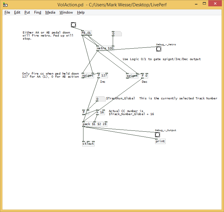
So Ill use the metronome in Live as my first example; I want to be able to turn the it on and off during various looping during performance (which is really a click track that uses hi hats samples instead of obnoxious ping pong sound). This happens by the primary action of a quick click as a toggle.
Depending on context, the click volume quite often needs to be varied as the song progresses in layers, so I want AA (Action A) to send inc controller up and AB dec etc. The same AA and AB are used when Im controlling volume on a track so it needs to be relative and not absolute.
No resets are required etc as only a relative controller will do, because I dont know what current level may be applied...absolute scaling is not really what Im after...I did try that originally but is not ideal.
This is a sketch I came up with...but the actual message for inc/dec type multi part controller is the mystery I need solved. This is using the track number + 16 as the cc number but I was thinking to parametise the input once its working. I realise this sketch misses the first fire from the pedal but I can live with that due to the extra simplicity...unless there is another easier way to do it?
HTH
Cheers
EDIT: Ok...answered by myself but hopefully help others..in Live, you set controller to Signed Bit 2. Then any cc can be treated as relative. The key to the step size is expected acceleration; 1-63 is increment speed, 65-127 is decrement speed ie value of 1 is slow ramp, 63 is large steps.
posted in technical issues
Build a MIDI controller with the Arduino, Firmata and Pure Data
Time to start contributing some knowledge back to the wonderful world that is the internet; today, a step by step nice and easy tutorial on getting started to building your own MIDI controllers with the arduino.
When researching for my ableton controller project, I didn’t find much out there about using firmata on an arduino to send data to software. The standard approach just seemed to be create the code in the arduino language, upload it to your board and hack one of those MIDI to USB cables as a bodge job way of getting the MIDI out of the arduino.
So why firmata and pure data? Well the whole idea of firmata is that you flash it to your arduino, and it throws out serial about whats going on with the arduino inputs and outputs, then you decide how the software treats the readings coming in and going out.
Theory out the way, lets build some controllers. You’ll need a few things…
HARDWARE:
An arduino and something to wire into it (for this i’ll be using a pot)
A USB cable for your arduino
SOFTWARE:
Arduino – http://arduino.cc/en/Main/Software
Pure Data – http://puredata.info/downloads
Firmata – http://at.or.at/hans/pd/objects.html#pduino
Something to patch your new controller into; like Reason or Ableton Live
- SETTING UP FIRMATA AND PURE DATA
Install Pure Data and create a folder to store all your patches somewhere. Unzip Firmata and add the files ‘arduino.pd’, ‘arduino-test.pd’ and ‘arduino-help.pd’ to your new Pure Data folder. The ‘arduino.pd’ file is the object that we use in PD for opening up communication with your arduino and routing it to PD. Done? Awesome, your software is almost set up.
- FLASHING FIRMATA TO YOUR ARDUINO
Install the latest version of arduino and open it up. Connect your arduino with the USB cable to your laptop (i’m using a macbook for this by the way). In the example patches, open up “Standard Firmata”, select your board (im using an arduino mega), and your serial port (look for tty.usbserial for use with a USB cable). Then compile and hit the upload button and your arduino is now ready to use firmata and communicate with Pure Data!
- WIRING UP A POT
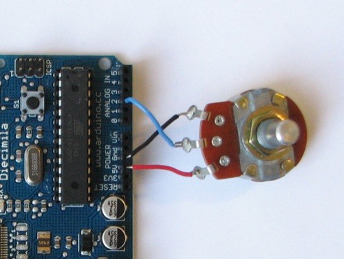
Potentiometers are cool, and theres a great arduino tutorial of how to wire one up here: http://www.arduino.cc/en/Tutorial/Potentiometer
Basically, all you need to know is that there are three pins; your two outer pins govern voltage flow across the pot, meaning one has to be 5V and the other has to be ground. It doesn’t matter which, but your 5v pin is going to be where your pot reads maximum, so convention dictates this should be the right hand pin. The center pin needs to be connected to an analog in on the arduino and will read the value of the pot as it sweeps from ground (0v) to 5v.
All wired up? Plug it into your laptop and open Pure Data, we’re ready to get things talking.
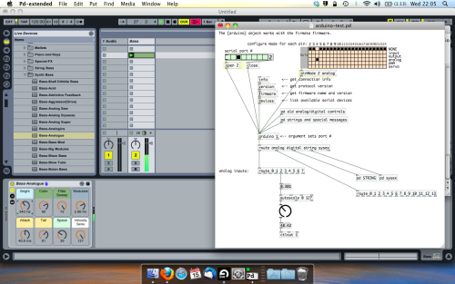
- SETTING UP OUR PATCH
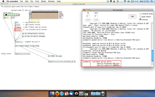
Open the example “arduino-test.pd” Pure Data patch you copied over earlier. It should look like this one…
The test patch has everything we need to open a connection and enable pins. Firstly, lets delete a bunch of stuff and make our window a bit bigger. Hit Command + E to enter edit mode in Pure Data.
Ok a quick explaination; the key component here is the ‘arduino’ object. This is being drawn from the file you copied in earlier, and is what communicated with your arduino. Here we can do everything to control the arduino from opening a connection, to receiving data.
The large grid allows us to set the mode of each pin on the arduino. Remember pins 0 and 1 are reserved for Rx and Tx. I’m using analog pin 4 for this demo, so I’ve set my pin mode for pin 4 to ‘analog’.
Now we can plug our arduino in and get a reading from the potentiometer.
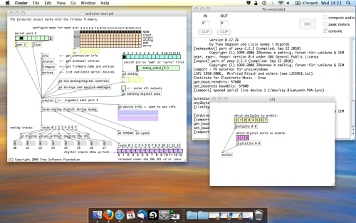
- ARDUINO INTO PURE DATA
With your arduino plugged in, hit command and E to bring us out of edit mode. In our patch, click on ‘Devices’ above the arduino object and open up the pure data terminal. (That other thing that loads with PD that has all the scary code in)
The “Devices” message connected to the arduino object pings your computer to find what devices are connected and on what serial ports. Since we’re using a USB cable to connect our arduino, we’re looking for something with ‘usbserial’ in it, in this case; port 2.
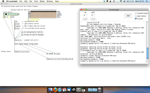
Select the relevent port in the green box at the top (remember the first box is ‘0’, second is ‘1’ and so forth) and hit ‘Open’ to establish a connection. Check the terminal to see if the connection was sucessful.

Now lets check we’re getting something in. Create a number box (Command + 3) and connect it to the relevent pin on the ‘Route analog’ box at the bottom. In this case, pin 4.
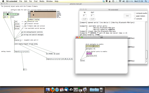
One more thing; if you’re not getting any readings in, you’ll need to click on ‘pd old analog/digital controls’ and enable your pins here too. What I tend to do in my patches is just not include the large grid but make my own ‘old pd’ controls custom to what i’m enabling/disabling to save space.
Here’s what the ‘old analog/digital controls’ subpatch looks like (pin 4 enabled)…
Come out of edit mode and check that you’ve got readings. If so congratulations! If not, troubleshoot, start with making sure your usb connection is opened, make sure all the correct pins are enabled (remember you’re counting from 0 not 1 on most of these buttons in PD, it’s just the way computers work).
- SCALING READINGS TO MIDI
So we’ve got a reading and chances are it’s to 3 decimal places between 0 to 1. No problem, create a new object (Command + 1) and type “autoscale 0 127”. This allows us to scale the input to a min and max value, in this case 0 to 127 of MIDI. Next, lets get things looking nice, create a new object and type “knob”. Connect this AFTER the autoscale object. (the knob is default set to read inputs from 0 to 127. Then create another number to display the scaled MIDI data coming out, and finally a new object and type “ctlout 1”.
It should look something like this…
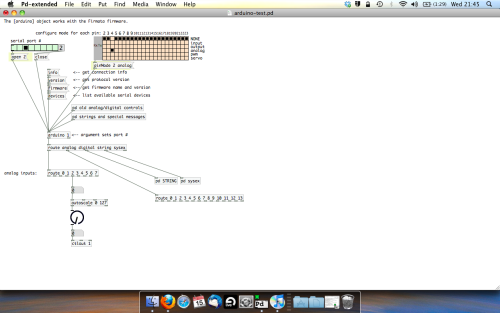
The second box should be outputing values from 0 – 127 now, and the knob giving a visual representation of your potentiometer.
Now lets patch it into ableton…
- PURE DATA TO ABLETON LIVE
Firstly, you’ll need to set up your macs IAC driver if you’ve not done this. Basically you’ll need to go into Audio/MIDI preferences and enable your IAC driver. Then create a new input and output. One for input to DAW and one for output from DAW. Google around for a tutorial on this, its really simple, a 30 second job.
After you’ve set up your IAC driver, go back to PD and go to preferences > MIDI Settings, and connect your IAC driver.
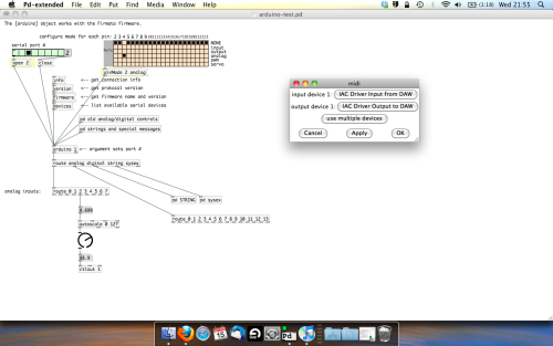
Open ableton and go to its MIDI preferences. Create a device listing for your IAC driver and enable its ins and outs into ableton like so…
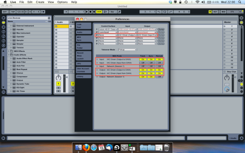
And thats it! Create an instrument and try to assign something! I’ve got it controlling the brightness of a bass sound here.
Shout out for Facu who requested this tutorial. Hopefully it’ll help some of you looking to get into this stuff and start building things but with no idea where to start.
 posted in tutorials