signalrate matrix-mixer~ ?
@jameslo marvellous, thank you very much!!!!
Just added inlets~ and outlets~
EDIT:
Guess what, I couldn't hear anything )
Bug fixed: [r~] instead of [r]
mm_send.pd
 posted in technical issues
signalrate matrix-mixer~ ?
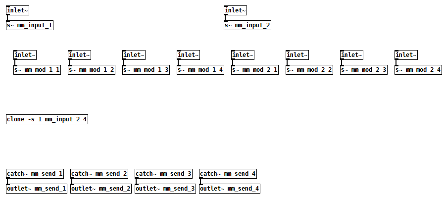
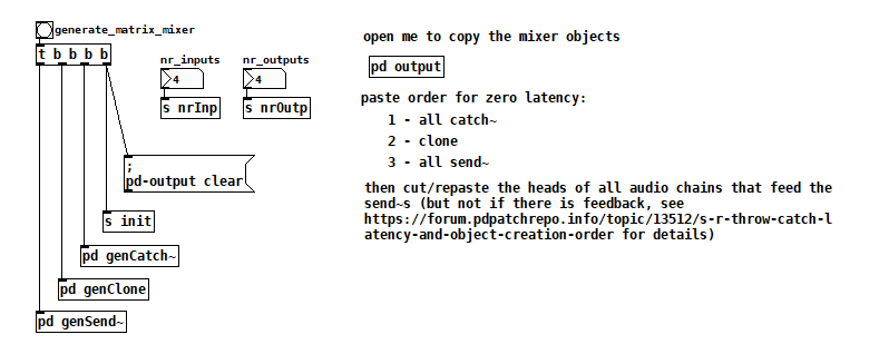
@lacuna This was a nice excuse to finally look into dynamic patching, thanks. I built something to create all the s~ and catch~ objects for me. It assumes that the modulation inputs are signal rate as you originally requested.
generate matrix mixer.pd
 posted in technical issues
s~/r~ throw~/catch~ latency and object creation order
For a topic on matrix mixers by @lacuna I created a patch with audio paths that included a s~/r~ hop as well as a throw~/catch~ hop, fully expecting each hop to contribute a 1 block delay. To my surprise, there was no delay. It reminded me of another topic where @seb-harmonik.ar had investigated how object creation order affects the tilde object sort order, which in turn determines whether there is a 1 block delay or not. Object creation order even appears to affect the minimum delay you can get with a delay line. So I decided to do a deep dive into a small example to try to understand it.
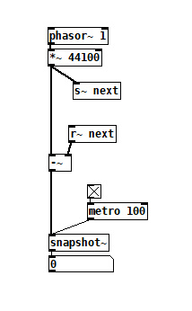
Here's my test patch: s~r~NoLatency.pd
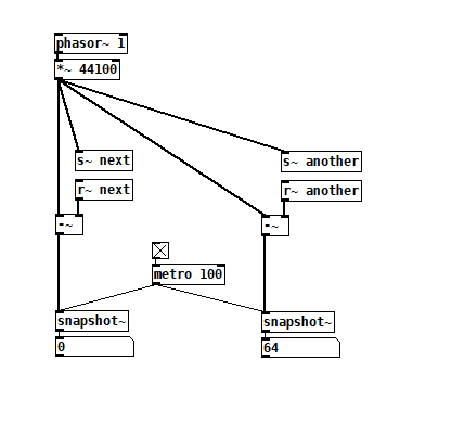
 The s~/r~ hop produces either a 64 sample delay, or none at all, depending on the order that the objects are created. Here's an example that combines both: s~r~DifferingLatencies.pd
 That's pretty kooky! On the one hand, it's probably good practice to avoid invisible properties like object creation order to get a particular delay, just as one should avoid using control connection creation order to get a particular execution order and use triggers instead. On the other hand, if you're not considering object creation order, you can't know what delay you will get without measuring it because there's no explicit sort order control. Well...technically there is one and it's described in G05.execution.order, but it defeats the purpose of having a non-local signal connection because it requires a local signal connection. Freeze dried water: just add water.
To reduce the number of cases I had to test, I grouped the objects into 4 subsets and permuted their creation orders:
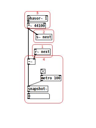 The order labeled in the diagram has no latency and is one that I just stumbled on, but I wanted to know what part of it is significant, so I tested all 24 permuations. (Methodology note: you can see the object creation order if you open the .pd file in a text editor. The lines that begin with "#X obj" list the objects in the order they were created.)
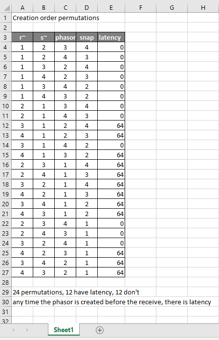
It appears that any time the phasor group is created before the r~, there is latency. Nothing else matters. Why would that be? To test if it's the whole audio chain feeding s~ that has to be created before, or only certain objects in that group, I took the first permutation with latency and cut/pasted [phasor~ 1] and [*~ 44100] in turn to push the object's creation order to the end. Only pushing [phasor~ 1] creation to the end made the delay go away, so maybe it's because that object is the head of the audio chain?
I also tested a few of these permutations using throw~/catch~ and got the same results. And I looked to see if connection creation order mattered but I couldn't find one that did and gave up after a while because there were too many cases to test.
So here's what I think is going on. Both [r~ next] and [phasor~ 1] are the heads of their respective locally connected audio chains which join at [-~]. Pd has to decide which chain to process first, and I assume that it has to choose the [phasor~ 1] chain in order for the data buffered by [s~ next] to be immediately available to [r~ next]. But why it should choose the [phasor~ 1] chain to go first if it's head is created later seems arbitrary to me. Can anyone confirm these observations and conjectures? Is this behavior documented anywhere? Can I count on this behavior moving forward? If so, what does good coding practice look like, when we want the delay and also when we don't?
posted in technical issues
Throw~/Catch~ and DSP block size issue
Hello,
I'm trying to create a modulation matrix for my patch, where I can route a bunch of control signals (LFO, ADSR, etc) to modulate various parameters using a matrix mixer topology (all mod sources can be sent to all destinations, and all destinations can receive a mix of all sources). I am naturally going for the [throw~] and [catch~] object to create one summing bus per destination (16 in total).
But I run into some errors there:
throw~ MO_pulse-width_mod: vector size mismatch
sigcatch summingBus1: unexpected vector size
I have figured out this has to do with DSP block size conflicts, as I have [block~] objects of varying sizes in several sub-patches. However I cannot get my head around DSP block size handling in Pd, and even less how to solve my issue. I have tried putting a number of size-matching [block~] objects on the subpatches containing the [throw~] and [catch~] objects and/or, where the source signal is actually being generated. None worked.
However, I noticed that if I replace [throw~]/[catch~] by {send~]/{receive~] and put a [block~ 64 1 1] in both sub-patches, the conflict is resolved. But using {send~]/{receive~] would greatly complexify the patch so I'd rather stick with [throw~]/[catch~] if I can.
I have tried to draw an accurate hierarchy of my current patch in the hope you may help me figure out where the mismatch occur. It's a tad complex as the modulation sources, the matrix mixer and the modulation destinations are all in different places of my patch. So I'm first using [s~] objects to send the various mod sources to the mod matrix, then use [throw~] objects to send these to the various "destinations" summing buses. I have added info where the signal generators are (~), [s~]/{r~] and {throw~/catch~] are all located in the hierarchy, as well as where some mandatory [block~] objects are (I cannot remove these as it will break my code).
Here it is:
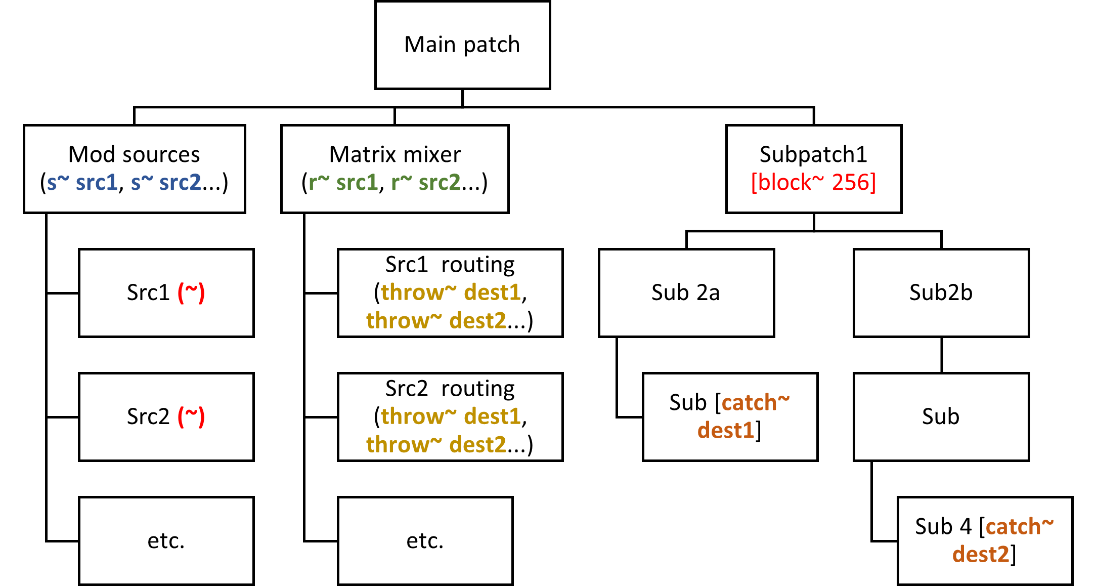
Hope my post and this graph somehow makes sense... 
 posted in technical issues
ltbl~ control a LED matrix with a Raspberry Pi and Pd
Hi everyone,
I wanted to display animations on a LED matrix connected to a Raspberry Pi and wrote this little external: https://github.com/fhchl/ltbl
It is a wrapper of https://github.com/hzeller/rpi-rgb-led-matrix. Just send a list with an RGB value for each pixel to the external to draw the picture on the LED matrix!
Hope this is useful for anyone. I used it for an animation on a Raspberry Pi 4 that mixed a dozen pix_images with pix_mix. Just dumped the mixed image directly into the external via pix_dump. The animation ran smooth with 30fps on a 64x64 matrix and was even quite OK when I had another Pd process running in parallel that did some sound processing. However, I used an external sound card and followed all the recommendations in the rpi-rgb-led-matrix readme for smooth frames.
 posted in extra~
Detecting multiple blobs using [pix_multiblob]
@Claire080499 My mistake. It is very hard without a camera.
So I misunderstood.
And in the help file [pd showblob] throws away "matrix" as a header anyway (it doesn't count for the dollar numbers).
That is why it's first bit of data is $3 and not $4..... that threw me.
So.
All the data is in one message (not one message for each blob).
matrix columns (no. of blobs detected) rows(always 9) data (9 parts) data (9 parts).......etc.
So for one blob...... matrix(binned) 1 9 $3 $4 $5 $6 $7 $8 $9 $10 $11
For 2 blobs............ matrix(binned) 2 9 $3 $4 $5 $6 $7 $8 $9 $10 $11 $12 $13 $14 $15 $16 $17 $18 $19 $20
And so what you need for [pd showblob] is the first 9 dollars for the first blob and the second 9 for the second.
$3 $4 $5 $6 $7 $8 $9 $10 $11
$12 $13 $14 $15 $16 $17 $18 $19 $20
Sorry again..... it's late..... this should work
blobby2.pd
The [0 0 0 0 0 0 0 0 0( message sets the values for blob 2 when it does not exist.
You might want to change those values or it might be just fine.
David.
 posted in technical issues
MIDI into [seq] and Markov chains
@porres Well, the [markov] object takes source material and generates something like an implicit probability transition matrix from that. If you already have a probability matrix, you only need a starting point and can play the markov chains immediately. A much more simpler abstraction can do that. Mixing the two approaches seems complicated, since [markov] follows a different philosophy, i.e. it allows adding more source material later in the process.
Interesting could be to have two separate abstractions: One to generate a probability matrix from source material and another one that plays markov chains from that. So you can have both approaches and combine them. ")
This would also be similar to the combination of [anal] and [prob], but as a generalized approach to have markov chains of arbitrary length.
The question is rather if it is a realistic scenario to have a complex probability matrix for markov chains of higher order. [markov] is built as a basic machine learning tool. ")
 posted in technical issues
Using PD more efficiently?
@s.elliot.perez Sorry...... It's likely...... I just grabbed it from a patch and it probably depends on other things.
Here is one that will run....... and is 100% vanilla....... matrix~.zip ....... It needs [count] again which is a vanilla abstraction.
I built it to replace [matrix~] from the cyclone library.
Open the test patch and then open [matrix~] and then open [pd mixer] to see how it builds.
If you open [matrix~] itself outside the test patch you will see that it is mostly empty. It only creates when it is given arguments.
David.
posted in technical issues
Dynamic send~ and receive~ in pure data ?
@Boran-Robert No. It is that way because the whole audio chain has to be built for the patch, and if it is broken and rebuilt it will produce a big bang as the dsp is turned off and on again.
It could be done with dynamic patching but the problem would remain.
You can make a matrix mixer using [cyclone/matrix~] which can soft fade inputs to outputs, or switch using [zexy/multiplex~] and [zexy/demultiplex~] but depending on exactly what you want to do with the zexy objects you might need to take down the audio to zero before you switch and then bring it back up.
Using those objects you do not break the audio chain.
The ext13 library has? / had settable [catch~] and [throw~] objects, but again, the name was not set until dsp was toggled on and off.
I made a few years ago a Plain Vanilla [matrix~] that is dynamically created at loadbang, but then of course has to be connected to its inlets and outlets, which can be done automatically..... matrix~.zip
...... but I think the cyclone library has been updated for 64-bit on most os's now.
David.
posted in technical issues
ofelia test grid
until now i created the matrix like that:
mt = {}          -- create the matrix
    for i=1,N do
      mt[i] = {}     -- create a new row
      for j=1,M do
        mt[i][j] = 0
      end
    end
in this version i create the matrix like that:
mt = {}          -- create the matrix
    for i=1,N do
      for j=1,M do
        mt[i*M + j] = 0
      end
    end
because it seems easier to access and to write to (i am not sure, but at least it works...).
i found the information about matrices and multi-dimensional arrays here: https://www.lua.org/pil/11.2.html
 posted in patch~