[small job offer] porting max external to pd
Edit 1: Took a shot porting it in this little textarea. Probably doesn't compile yet...
Edit 2: Ok, this should compile now. I haven't actually tried to instantiate it yet, though. It's possible I set it up with the wrong number of xlets.
Edit 3: Seems to instantiate ok. It appears it doesn't take signal input so the CLASS_MAINSIGNALIN macro is neccessary. Just comment that part out to make it a control signal.
Note-- in my port it's called [vb_fourses~] for the reason noted below.
I have no idea if the algorithm behaves correctly, but it does output sound.
Btw-- AFAICT you should be able to compile this external for the 64-bit version of Purr Data and it should work properly. It doesn't require a special 64-bit codepath in Pd so I commented that part out.
Btw 2-- there should probably be a "best practices" rule that states you can only name your class something that is a legal C function name. Because this class doesn't follow that practice I made a mistake in the port. Further, the user will make a mistake because I had to change the class name. If I had instead made the setup function a different name than the creator I would create an additional problem that would force users to declare the lib before using it. Bad all around, and not worth whatever benefit there is to naming a class "foo.bar" instead of "foo_bar"
/*
#include "ext.h"
#include "ext_obex.h"
#include "z_dsp.h"
#include "ext_common.h"
*/

#include "m_pd.h"
#include "math.h"

/*
    a chaotic oscillator network
    based on descriptions of the 'fourses system' by ciat-lonbarde
    www.ciat-lonbarde.net

    07.april 2013, volker b?hm
*/

#define NUMFOURSES 4

static void *myObj_class;

typedef struct {
    // this is a horse... basically a ramp generator
    double      val;
    double      inc;
    double      dec;
    double      adder;
    double      incy, incym1;       // used for smoothing
    double      decy, decym1;       // used for smoothing
} t_horse;

typedef struct {
    t_object    x_obj;
    double      r_sr;
    t_horse     fourses[NUMFOURSES+2];  // four horses make a fourse...
    double      smoother;
    t_sample x_f;
} t_myObj;


// absolute limits
static void myObj_hilim(t_myObj *x, t_floatarg input);
static void myObj_lolim(t_myObj *x, t_floatarg input);

// up and down freqs for all oscillators
static void myObj_upfreq(t_myObj *x, t_floatarg freq1, t_floatarg freq2, t_floatarg freq3, t_floatarg freq4);
static void myObj_downfreq(t_myObj *x, t_floatarg freq1, t_floatarg freq2, t_floatarg freq3, t_floatarg freq4);

static void myObj_smooth(t_myObj *x, t_floatarg input);
static void myObj_info(t_myObj *x);

// DSP methods
static void myObj_dsp(t_myObj *x, t_signal **sp);
static t_int *myObj_perform(t_int *w);
//void myObj_dsp64(t_myObj *x, t_object *dsp64, short *count, double samplerate,
//               long maxvectorsize, long flags);
//void myObj_perform64(t_myObj *x, t_object *dsp64, double **ins, long numins,
//                     double **outs, long numouts, long sampleframes, long flags, void *userparam);
//

static void *myObj_new( t_symbol *s, int argc, t_atom *argv);
//void myObj_assist(t_myObj *x, void *b, long m, long a, char *s);


void vb_fourses_tilde_setup(void) {
    t_class *c;
    myObj_class = class_new(gensym("vb_fourses~"), (t_newmethod)myObj_new, 0, sizeof(t_myObj),
                  0, A_GIMME, NULL);
    c = myObj_class;
    class_addmethod(c, (t_method)myObj_dsp, gensym("dsp"), A_CANT, 0);
//  class_addmethod(c, (t_method)myObj_dsp64, gensym("dsp64"), A_CANT, 0);
    class_addmethod(c, (t_method)myObj_smooth, gensym("smooth"), A_FLOAT, 0);
    class_addmethod(c, (t_method)myObj_hilim, gensym("hilim"), A_FLOAT, 0);
    class_addmethod(c, (t_method)myObj_lolim, gensym("lolim"), A_FLOAT, 0);
    class_addmethod(c, (t_method)myObj_upfreq, gensym("upfreq"), A_FLOAT, A_FLOAT, A_FLOAT, A_FLOAT, 0);
    class_addmethod(c, (t_method)myObj_downfreq, gensym("downfreq"), A_FLOAT, A_FLOAT, A_FLOAT, A_FLOAT, 0);

    class_addmethod(c, (t_method)myObj_info, gensym("info"), 0);
    //class_addmethod(c, (t_method)myObj_assist, "assist", A_CANT,0);
    CLASS_MAINSIGNALIN(myObj_class, t_myObj, x_f);
//  class_dspinit(c);
//  class_register(CLASS_BOX, c);

    post("vb_fourses~ by volker b?hm\n");

//  return 0;
}


static void myObj_smooth(t_myObj *x, t_floatarg input) {
//  input = CLAMP(input, 0., 1.);
   if (input < 0.) input = 0;
     if (input > 1.) input = 1;
    x->smoother = 0.01 - pow(input,0.2)*0.01;
}

static void myObj_hilim(t_myObj *x, t_floatarg input) {
    x->fourses[0].val = input;      // store global high limit in fourses[0]
}
static void myObj_lolim(t_myObj *x, t_floatarg input) {
    x->fourses[5].val = input;      // store global low limit in fourses[5]
}

static void myObj_upfreq(t_myObj *x, t_floatarg freq1, t_floatarg freq2, t_floatarg freq3, t_floatarg freq4) {
    x->fourses[1].inc = fabs(freq1)*4*x->r_sr;
    x->fourses[2].inc = fabs(freq2)*4*x->r_sr;
    x->fourses[3].inc = fabs(freq3)*4*x->r_sr;
    x->fourses[4].inc = fabs(freq4)*4*x->r_sr;
}

static void myObj_downfreq(t_myObj *x, t_floatarg freq1, t_floatarg freq2, t_floatarg freq3, t_floatarg freq4) {
    x->fourses[1].dec = fabs(freq1)*-4*x->r_sr;
    x->fourses[2].dec = fabs(freq2)*-4*x->r_sr;
    x->fourses[3].dec = fabs(freq3)*-4*x->r_sr;
    x->fourses[4].dec = fabs(freq4)*-4*x->r_sr;
}


//#pragma mark 64bit dsp-loop ------------------

//void myObj_dsp64(t_myObj *x, t_object *dsp64, short *count, double samplerate,
//               long maxvectorsize, long flags) {
//  object_method(dsp64, gensym("dsp_add64"), x, myObj_perform64, 0, NULL);
//
//  if(samplerate<=0) x->r_sr = 1.0/44100.0;
//  else x->r_sr = 1.0/samplerate;
//
//
//}

//static void myObj_perform64(t_myObj *x, t_object *dsp64, double **ins, long numins,
//                     double **outs, long numouts, long sampleframes, long flags, void *userparam){
//
//  t_double **output = outs;
//  int vs = sampleframes;
//  t_horse *fourses = x->fourses;
//  double val, c, hilim, lolim;
//  int i, n;
//
//  if (x->x_obj.z_disabled)
//      return;
//
//  c = x->smoother;
//  hilim = fourses[0].val;
//  lolim = fourses[5].val;
//
//  for(i=0; i<vs; i++)
//   {
//      for(n=1; n<=NUMFOURSES; n++) {
//          // smoother
//          fourses[n].incy = fourses[n].inc*c + fourses[n].incym1*(1-c);
//          fourses[n].incym1 = fourses[n].incy;
//
//          fourses[n].decy = fourses[n].dec*c + fourses[n].decym1*(1-c);
//          fourses[n].decym1 = fourses[n].decy;
//
//          val = fourses[n].val;
//          val += fourses[n].adder;
//
//          if(val <= fourses[n+1].val || val <= lolim ) {
//              fourses[n].adder = fourses[n].incy;
//          }
//          else if( val >= fourses[n-1].val || val >= hilim ) {
//              fourses[n].adder = fourses[n].decy;
//          }
//
//          output[n-1][i] = val;
//
//          fourses[n].val = val;
//      }
//   }
//
//  return;
//
//}

//#pragma mark 32bit dsp-loop ------------------

static void myObj_dsp(t_myObj *x, t_signal **sp)
{
    dsp_add(myObj_perform, 6, x, sp[0]->s_vec, sp[1]->s_vec, sp[2]->s_vec, sp[3]->s_vec, sp[0]->s_n);

    if(sp[0]->s_sr<=0)
        x->r_sr = 1.0/44100.0;
    else x->r_sr = 1.0/sp[0]->s_sr;
}


static t_int *myObj_perform(t_int *w)
{
    t_myObj *x = (t_myObj*)(w[1]);
    t_float *out1 = (float *)(w[2]);
    t_float *out2 = (float *)(w[3]);
    t_float *out3 = (float *)(w[4]);
    t_float *out4 = (float *)(w[5]);
    int vs = (int)(w[6]);

// Hm... not sure about this member. I don't think we can disable individual
// objects in Pd...
//    if (x->x_obj.z_disabled)
//        goto out;

    t_horse *fourses = x->fourses;
    double val, c, hilim, lolim;
    int i, n;

    c = x->smoother;
    hilim = fourses[0].val;
    lolim = fourses[5].val;

    for(i=0; i<vs; i++)
     {
        for(n=1; n<=NUMFOURSES; n++) {
            // smoother
            fourses[n].incy = fourses[n].inc*c + fourses[n].incym1*(1-c);
            fourses[n].incym1 = fourses[n].incy;

            fourses[n].decy = fourses[n].dec*c + fourses[n].decym1*(1-c);
            fourses[n].decym1 = fourses[n].decy;

            val = fourses[n].val;
            val += fourses[n].adder;

            if(val <= fourses[n+1].val || val <= lolim ) {
                fourses[n].adder = fourses[n].incy;
            }
            else if( val >= fourses[n-1].val || val >= hilim ) {
                fourses[n].adder = fourses[n].decy;
            }

            fourses[n].val = val;
        }

        out1[i] = fourses[1].val;
        out2[i] = fourses[2].val;
        out3[i] = fourses[3].val;
        out4[i] = fourses[4].val;

     }
//out:
    return w+7;
}

static void myObj_info(t_myObj *x) {
    int i;
    // only fourses 1 to 4 are used
    post("----- fourses.info -------");
    for(i=1; i<=NUMFOURSES; i++) {
        post("fourses[%ld].val = %f", i, x->fourses[i].val);
        post("fourses[%ld].inc = %f", i, x->fourses[i].inc);
        post("fourses[%ld].dec = %f", i, x->fourses[i].dec);
        post("fourses[%ld].adder = %f", i, x->fourses[i].adder);
    }
    post("------ end -------");
}

void *myObj_new(t_symbol *s, int argc, t_atom *argv)
{
    t_myObj *x = (t_myObj *)pd_new(myObj_class);
//  dsp_setup((t_pxobject*)x, 0);
    outlet_new((t_object *)x, &s_signal);
    outlet_new((t_object *)x, &s_signal);
    outlet_new((t_object *)x, &s_signal);
    outlet_new((t_object *)x, &s_signal);

    x->r_sr = 1.0/sys_getsr();
    if(sys_getsr() <= 0)
        x->r_sr = 1.0/44100.f;

    int i;
    for(i=1; i<=NUMFOURSES; i++) {
        x->fourses[i].val = 0.;
        x->fourses[i].inc = 0.01;
        x->fourses[i].dec = -0.01;
        x->fourses[i].adder = x->fourses[i].inc;

    }
    x->fourses[0].val = 1.; // dummy 'horse' only used as high limit for fourses[1]
    x->fourses[5].val = -1.;    // dummy 'horse' only used as low limit for fourses[4]

    x->smoother = 0.01;

    return x;
}


//void myObj_assist(t_myObj *x, void *b, long m, long a, char *s) {
//  if (m==1) {
//      switch(a) {
//          case 0: sprintf (s,"message inlet"); break;
//      }
//  }
//  else {
//      switch(a) {
//          case 0: sprintf (s,"(signal) signal out osc1"); break;
//          case 1: sprintf(s, "(signal) signal out osc2"); break;
//          case 2: sprintf(s, "(signal) signal out osc3"); break;
//          case 3: sprintf(s, "(signal) signal out osc4"); break;
//      }
//
//  }
//}
 posted in technical issues
[Solved] Only have one instance of Pd open on RPi...
@whale-av thanks for your reply. I don't know if you are in the US, but if so Happy Thanksgiving.
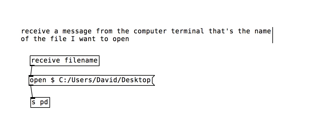
What I am trying to do, and I think this is a possible way to do it, is send a message from the computer terminal using a python script to the inside of Pd to open a file. My image sort of describes the intent. In your example it's all happening within Pd and I need it to get a message from the computer terminal into Pd. Or, using the computer terminal, open a Pd file in the already opend instance of Pd.
I never got Shell to work, but after looking at it I realized it can send a message to the terminal of the computer, but I don't know if it can receive a message from the terminal, so maybe it's not possible using shell.
Let me know if there's some other ideas or options. I'm still researching this.
Thank You. Nick
 posted in technical issues
patch recreation of Native Instruments' Kontakt's "authentic expression technology"
hello guys,
I used the last few days to analyze the authentic expression technology filter in Native Instruments' "Kontakt" to make my own remake of it in form of a multiple input audio source morphing tool that functions exactly like the AET filter in NI Kontakt. I'll upload a video demo on how it's done, soon. For now here's the description. This following little patch is a recreation of how Kontakt's modwheel behaves in relation to key velocity. You need it for an authentic AET experience.
Henry velocity plus modwheel merger.pd
What Kontakt's channel vocoder does is this: It swaps the carrier and modulator input signal everytime a morphing has finished while at the same time routing another audio source into the respectively muted input.
This can easily be done with freeware, too - with up to 12 audio sources!
Here is how:
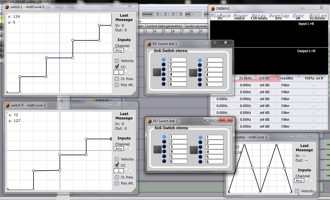 this picture shows all softwares needed to fake the AET filter functioning.: a modular host / VST wrapper; Midicurve; RD switch 6×6; DtblkFXs
routing and parameter assignment:
- MIDI keyboard into Pd, from Pd to your DAW, inside your DAW rout it into all 'Midicurve'-plugins
- rout first and second Midicurves into a 6x6 switch each; assigning 6×6's input switching parameter to the Midi CC coming from the respective Midicurve plug-in
- rout third Midicurve to DtblkFXs, assigning it's "0.Val" parameter to Midi output CC coming from that respective Midicurve
- rout your audio sources (synths / samplers / microphones) into the RD switches - instruments 1,3,5,7 & 9 into one switch and the instruments 2,4,6 & 8 into the other switch (all instruments get a different input at the RD switches - don't put all of them into the first audio channel, otherwise they won' t morph)
- draw the transfer functions of the Midicurves as seen in the picture and make sure to place a hook at "CC" and select the CC of your modwheel!
If you turn your modwheel up, now, the switches should change their input channels exactly in the moment when a full morphing from one source to the next has been finished. - adjust DtblkFXs as seen in the picture!
Much fun with your own totally free AET morphing tool!
 posted in patch~
Midi controller not seen by Pd, but seen by system. Rpi3. Pd .49
Hi,
First of all I want to say thank you to this forum community. I have been doing Pd for a few years, so still total newbie, but I have made a lot of progress due to the immeasurable amount of knowledge and help from this community.
I got a disk image from this thread:
https://forum.pdpatchrepo.info/topic/11626/pd-48-on-raspberry-pi-3/14
I have a Raspberry Pi 3, running Pure Data .49.
In my previous disk image Pd automatically recognized my midi controller. But in this new one Pd does not see my controller at all. I saw another post detailing my exact problem, but it was not solved. I would guess that others that must be having this problem, or that it will be coming up going forward. I'll go into detail, but this thread details a very similar issue:
https://forum.pdpatchrepo.info/topic/11485/rpi-no-midi-input-or-output-found
Also, my disk image has Jack installed on it. After spending hours trying to figure out Jack, and qjackctlm (with zero success), I thought I would just ask here. I'd rather not use Jack if possible as everything was works fine without it on my other disk image.
When I launch Pd, with my midi controller plugged in, it does not recognize it. Either in OSS-Midi or ALSA.
In the terminal, if I run: amidi -l
I see my controller MIDI/MOCA for LUFA MIDI 1
So I think everything is fine with the Pi.
If I run: pd -listdev in terminal I see my midi controller being recognized as an audio input and output device, but it says:
no midi input devices found
no midi output devices found
so it does not see my interface as a midi device
Any suggestions at all on my to get Pd to see my midi controller? I'm kind of stuck and have tried everything I can think of.
Thank you again for any input.
posted in technical issues
MIDI Delay with weird fix (has now become an ASIO issue)
Hi there!
New to PD and its really great to use. I have a USB MIDI keyboard which, in any program, has huge input lag, making it unplayable (we're talking quarter of a second here, which is huge in timing terms). This was the same in PD, until I opened Audio Settings in PD and started, gradually, nudging down the delay (msec) value. Since that, I get no noticeable input lag at a msec value of 25 (lower breaks with horrible input lag, higher obviously increases input lag because, well, its a delay), however the input lag comes back if I close the Audio Settings window. After applying and not closing the window, there is no problem. I also notice launching my email client with the window open created huge lag, but I see that as being normal, as you're putting more work on the CPU.
My setup for testing is as follows: USB MIDI keyboard -> PD -> simple input to output patch -> USB MIDI adapter (not the keyboard, a different one) -> Yamaha CBX-T3 MIDI sound module.
This system is running windows 10 64Bit
Preferably, I'd like to remove delay for ALL programs. Worst case I'd like to be able to use PD's midi functions without the Audio Settings window open.
Thanks for any help.
EDIT: Clsoing the Audio Settings window and waiting about 5 seconds fixes the delay issue for PD., still have program delay though, such as Ableton.
 posted in technical issues
Trying to build a basic neural net with ann
Ok, nice patch. How many hidden layers do you use? maybe more of them could make a difference.
Also, here is a quote from ann manual :
"
Tip: inputs should be 0 centered
the example of chord recognition should not work well (hard to train)
because possible input values go from 30 to 90, you should remap them so
they go from -30 to 30
Notice how the inputs in ann/examples/ann_mlp_example2 go from -1 to 1
If you can't make inputs 0 centered they should at least start from 0
Tip: inputs should be normalized
If you have one input that goes from -10 to 10 and another input that goes
from -1 to 1 the first input will be more important than the second input
OUTPUTS:
Each "meaning" you want your ANN to detect should have its own output.
Notice ann/examples/ann_mlp_example2:
"Calm" and "chaos" have their outputs even if they are related.
I could have set only 1 output 0 for calm and 1 for chaos.
But having separated outputs I can see if my ANN has been trained well or
not, but also could be that a situation is neither calm nor chaotic, or
somehow calm AND chaotic.. " // davide morelli
I cannot say from the patch you've made if you had read it or not, in this case I thougt you'd be interested.
 posted in technical issues
Lissa Executable / ofxOfelia compile error (Solved)
@cuinjune I tried to compile the lissa seq patch. but when i open the executable it opens only a small empty window.
i also tried to compile a help patch for testing, with the same result.
but your example works fine(Win32Example).
 posted in libpd / webpd
Build a MIDI controller with the Arduino, Firmata and Pure Data
Time to start contributing some knowledge back to the wonderful world that is the internet; today, a step by step nice and easy tutorial on getting started to building your own MIDI controllers with the arduino.
When researching for my ableton controller project, I didn’t find much out there about using firmata on an arduino to send data to software. The standard approach just seemed to be create the code in the arduino language, upload it to your board and hack one of those MIDI to USB cables as a bodge job way of getting the MIDI out of the arduino.
So why firmata and pure data? Well the whole idea of firmata is that you flash it to your arduino, and it throws out serial about whats going on with the arduino inputs and outputs, then you decide how the software treats the readings coming in and going out.
Theory out the way, lets build some controllers. You’ll need a few things…
HARDWARE:
An arduino and something to wire into it (for this i’ll be using a pot)
A USB cable for your arduino
SOFTWARE:
Arduino – http://arduino.cc/en/Main/Software
Pure Data – http://puredata.info/downloads
Firmata – http://at.or.at/hans/pd/objects.html#pduino
Something to patch your new controller into; like Reason or Ableton Live
- SETTING UP FIRMATA AND PURE DATA
Install Pure Data and create a folder to store all your patches somewhere. Unzip Firmata and add the files ‘arduino.pd’, ‘arduino-test.pd’ and ‘arduino-help.pd’ to your new Pure Data folder. The ‘arduino.pd’ file is the object that we use in PD for opening up communication with your arduino and routing it to PD. Done? Awesome, your software is almost set up.
- FLASHING FIRMATA TO YOUR ARDUINO
Install the latest version of arduino and open it up. Connect your arduino with the USB cable to your laptop (i’m using a macbook for this by the way). In the example patches, open up “Standard Firmata”, select your board (im using an arduino mega), and your serial port (look for tty.usbserial for use with a USB cable). Then compile and hit the upload button and your arduino is now ready to use firmata and communicate with Pure Data!
- WIRING UP A POT
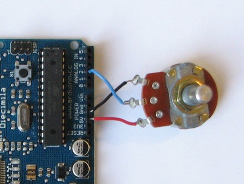
Potentiometers are cool, and theres a great arduino tutorial of how to wire one up here: http://www.arduino.cc/en/Tutorial/Potentiometer
Basically, all you need to know is that there are three pins; your two outer pins govern voltage flow across the pot, meaning one has to be 5V and the other has to be ground. It doesn’t matter which, but your 5v pin is going to be where your pot reads maximum, so convention dictates this should be the right hand pin. The center pin needs to be connected to an analog in on the arduino and will read the value of the pot as it sweeps from ground (0v) to 5v.
All wired up? Plug it into your laptop and open Pure Data, we’re ready to get things talking.
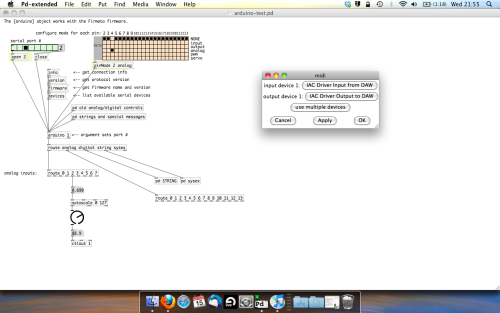
- SETTING UP OUR PATCH
Open the example “arduino-test.pd” Pure Data patch you copied over earlier. It should look like this one…
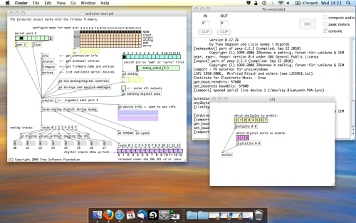
The test patch has everything we need to open a connection and enable pins. Firstly, lets delete a bunch of stuff and make our window a bit bigger. Hit Command + E to enter edit mode in Pure Data.
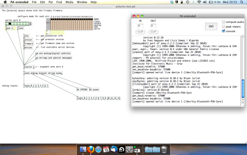
Ok a quick explaination; the key component here is the ‘arduino’ object. This is being drawn from the file you copied in earlier, and is what communicated with your arduino. Here we can do everything to control the arduino from opening a connection, to receiving data.
The large grid allows us to set the mode of each pin on the arduino. Remember pins 0 and 1 are reserved for Rx and Tx. I’m using analog pin 4 for this demo, so I’ve set my pin mode for pin 4 to ‘analog’.
Now we can plug our arduino in and get a reading from the potentiometer.
- ARDUINO INTO PURE DATA
With your arduino plugged in, hit command and E to bring us out of edit mode. In our patch, click on ‘Devices’ above the arduino object and open up the pure data terminal. (That other thing that loads with PD that has all the scary code in)
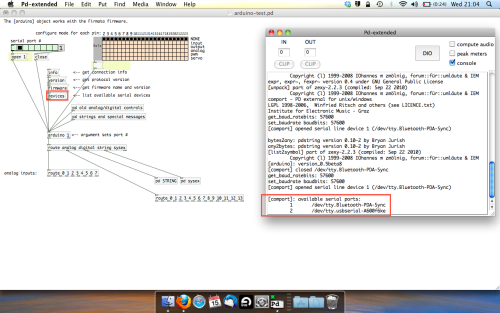
The “Devices” message connected to the arduino object pings your computer to find what devices are connected and on what serial ports. Since we’re using a USB cable to connect our arduino, we’re looking for something with ‘usbserial’ in it, in this case; port 2.
Select the relevent port in the green box at the top (remember the first box is ‘0’, second is ‘1’ and so forth) and hit ‘Open’ to establish a connection. Check the terminal to see if the connection was sucessful.

Now lets check we’re getting something in. Create a number box (Command + 3) and connect it to the relevent pin on the ‘Route analog’ box at the bottom. In this case, pin 4.
One more thing; if you’re not getting any readings in, you’ll need to click on ‘pd old analog/digital controls’ and enable your pins here too. What I tend to do in my patches is just not include the large grid but make my own ‘old pd’ controls custom to what i’m enabling/disabling to save space.
Here’s what the ‘old analog/digital controls’ subpatch looks like (pin 4 enabled)…
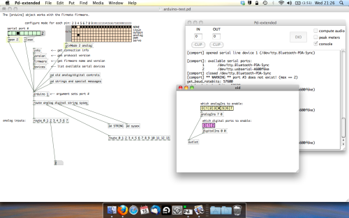
Come out of edit mode and check that you’ve got readings. If so congratulations! If not, troubleshoot, start with making sure your usb connection is opened, make sure all the correct pins are enabled (remember you’re counting from 0 not 1 on most of these buttons in PD, it’s just the way computers work).
- SCALING READINGS TO MIDI
So we’ve got a reading and chances are it’s to 3 decimal places between 0 to 1. No problem, create a new object (Command + 1) and type “autoscale 0 127”. This allows us to scale the input to a min and max value, in this case 0 to 127 of MIDI. Next, lets get things looking nice, create a new object and type “knob”. Connect this AFTER the autoscale object. (the knob is default set to read inputs from 0 to 127. Then create another number to display the scaled MIDI data coming out, and finally a new object and type “ctlout 1”.
It should look something like this…
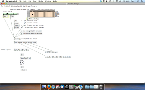
The second box should be outputing values from 0 – 127 now, and the knob giving a visual representation of your potentiometer.
Now lets patch it into ableton…
- PURE DATA TO ABLETON LIVE
Firstly, you’ll need to set up your macs IAC driver if you’ve not done this. Basically you’ll need to go into Audio/MIDI preferences and enable your IAC driver. Then create a new input and output. One for input to DAW and one for output from DAW. Google around for a tutorial on this, its really simple, a 30 second job.
After you’ve set up your IAC driver, go back to PD and go to preferences > MIDI Settings, and connect your IAC driver.
Open ableton and go to its MIDI preferences. Create a device listing for your IAC driver and enable its ins and outs into ableton like so…
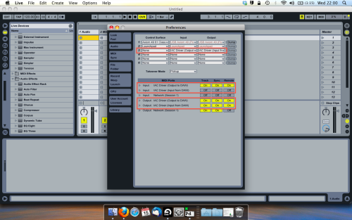
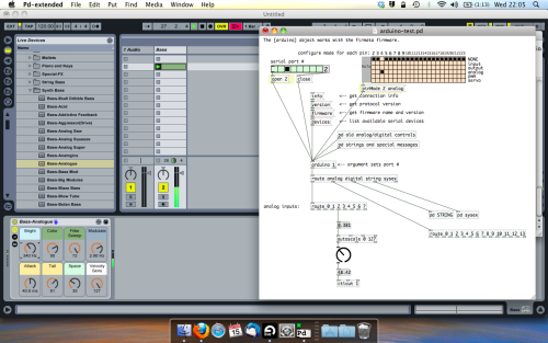
And thats it! Create an instrument and try to assign something! I’ve got it controlling the brightness of a bass sound here.
Shout out for Facu who requested this tutorial. Hopefully it’ll help some of you looking to get into this stuff and start building things but with no idea where to start.
 posted in tutorials
HID Identical Dance Mats use different symbol for the same control through [HID]
When running dmesg from the terminal to print out the kernal buffer it reads
.271124] usb 7-1: new low-speed USB device number 3 using uhci_hcd
[21052.428183] usb 7-1: New USB device found, idVendor=0079, idProduct=0011
[21052.428191] usb 7-1: New USB device strings: Mfr=0, Product=2, SerialNumber=0
[21052.428196] usb 7-1: Product: USB Gamepad
[21052.454234] input: USB Gamepad as /devices/pci0000:00/0000:00:1d.1/usb7/7-1/7-1:1.0/0003:0079:0011.0006/input/input23
[21052.505271] dragonrise 0003:0079:0011.0006: input,hidraw1: USB HID v1.10 Joystick [USB Gamepad ] on usb-0000:00:1d.1-1/input0
[21057.059115] usb 6-1: new low-speed USB device number 5 using uhci_hcd
[21057.216253] usb 6-1: New USB device found,****** idVendor=0079, idProduct=0011******
[21057.216260] usb 6-1: New USB device strings: Mfr=0, Product=2, SerialNumber=0
[21057.216265] usb 6-1: Product: USB Gamepad
[21057.242315] input: USB Gamepad as /devices/pci0000:00/0000:00:1d.0/usb6/6-1/6-1:1.0/0003:0079:0011.0007/input/input24
[21057.242781] dragonrise 0003:0079:0011.0007: input,hidraw2: USB HID v1.10 Joystick [USB Gamepad ] on usb-0000:00:1d.0-1/input0
So both devices contain the same idVendor=0079, idProduct=0011 tags that [hid] can find. Is there a way to differentiate between to two devices by another serial number so I can create seperate mappings for them in Pd?
 posted in technical issues
Sysex program dump with random zeros
Okay ;that's what I suspected you were doing. It is possible to use the MTP serial directly with linux and the mtpav driver, though this requires a machine with true hardware parallel port access (USB adapters won't cut it) and is limited to MIDI output only as the driver is a hack that was never finished. I used to run mine that way with a second USB MIDI interface connected to one or more of the MTP's unused routed MIDI outputs (there is, BTW still no way to connect the MTP USB version directly to a Linux system as it doesn't use a standard USB MIDI driver)
As far as the kernel is concerned, I've only ever used lowlatency or RT kernels for MIDI stuff. I don't know how a generic kernel would affect this problem but it's probably best avoided as they are not specifically built for multimedia.
Now read closely as this is where it becomes stupidly complicated.
First, make sure that the problem is internal to Pd. Your interfaces are probably not the issue (since Pd is only seeing the UM-1 driver I don't think the MTP even figures in here). However, the chosen MIDI API can get in the way, specifically in the case of the unfinished JACK MIDI. JACK MIDI presently can only pass SYSEX as short realtime messages. SYSEX data dumps will disappear if sent into the current JACK MIDI system. ALSA works OK. OSS probably too, but I have not tried it.
If that stuff is ruled out and you are still getting problems, it probably has to do with a set of longstanding bugs/oversights in the Pd MIDI stack that can affect the input, output, or both.
On the output side there is a sysex transmission bug which affects all versions of Pd Vanilla before 0.48. The patch that fixed Vanilla had already been applied to L20rk/PurrData for some time (years, I think). The output bug did not completely disable SYSEX output. What it did was to miss-format SYSEX in a way that can't be understood by most modern midi applications, including the standard USB MIDI driver software (SYSEX output from Pd is ignored and the driver/interface will not transmit anything). You would not notice this bug with a computer connected directly to an MTP because the MAC and Linux MTP drivers are programmed to pass raw unformatted MIDI.
If this is the problem and you have to use a pre-0.48 version of Vanilla it can be patched. See:
https://sourceforge.net/p/pure-data/bugs/1272/
On the MIDI input side of Pd we have 2 common problems. One is the (annoyingly unfinished but nevertheless implemented) input to output timestamping buffer that's supposed to provide sample-accurate MIDI at the output (if it was finished). This can be minimized with the proper startup flags (for a MIDI-only instance of Pd, -rt -noaudio -audiobuf 1 -sleepgrain 0.5 works for me) or completely defeated with a source code tweak to the s_midi.c file. This may not be the source of your particular problem as it usually only affects the time it takes to pass messages from input to output, but is worth mentioning as it can be very annoying regardless.
With SYSEX dumps it is more likely that the problem lies with the MIDI queue size. This is very common and I experienced it myself when trying to dump memory from a Korg Electribe Ea-1.. The current version of Pd limits the queue to a size of 512 (even worse it used to be 20) and any input larger than that will get truncated w/no error warning. There is not yet any way to change this with startup flags or user settings. This can only be "fixed" by a different tweak to s_midi.c and recompiling the app.
The attached text files are derived from the Pd-list and will show the specific mods that need to be made to s_midi.c.
 posted in technical issues