Phase modulation FM8 emulation troubles
@RandLaneFly "When the mod index is maxed out it sounds way more extreme and than on the FM8."
Without looking at your patch --
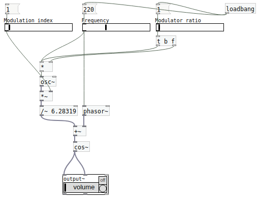
I've always done FM (leaving PM aside for a moment) such that index = 1 means that, if f is the main frequency, the carrier frequency oscillates between 0 and 2f.
mod_phase = phasor(0 .. 2pi) at (f * ratio) Hz

mod = sin(mod_phase) * index

car_phase = phasor(0 .. 2pi) at (f + (f * mod)) Hz = (f * (1 + mod)) Hz

carrier = sin(car_phase)
If you do phase modulation like this, then index has exactly the same meaning.
mod_phase = phasor(0 .. 2pi) at (f * ratio) Hz

mod = sin(mod_phase) * index

car_phase = mod + phasor(0 .. 2pi) at f Hz

carrier = sin(car_phase)
Takeaway: if the phasor goes 0 to 2pi, then you don't need to do any extra scaling on the modulation index for PM and FM to be compatible.
The catch in Pure Data is that the phasor is not 0 to 2pi. It's 0 to 1.
So, for phase modulation, you have to scale the index down by 2pi: mod --> [/ 6.28319].
hjh
 posted in technical issues
PD's scheduler, timing, control-rate, audio-rate, block-size, (sub)sample accuracy,
Hello, 
this is going to be a long one.
After years of using PD, I am still confused about its' timing and schedueling.
I have collected many snippets from here and there about this topic,
-wich all together are really confusing to me.
*I think it is very important to understand how timing works in detail for low-level programming … *
(For example the number of heavy jittering sequencers in hard and software make me wonder what sequencers are made actually for ? lol )
This is a collection of my findings regarding this topic, a bit messy and with confused questions.
I hope we can shed some light on this.


- a)
The first time, I had issues with the PD-scheduler vs. how I thought my patch should work is described here:
https://forum.pdpatchrepo.info/topic/11615/bang-bug-when-block-1-1-1-bang-on-every-sample
The answers where:
„
[...] it's just that messages actually only process every 64 samples at the least. You can get a bang every sample with [metro 1 1 samp] but it should be noted that most pd message objects only interact with each other at 64-sample boundaries, there are some that use the elapsed logical time to get times in between though (like vsnapshot~)
also this seems like a very inefficient way to do per-sample processing..
https://github.com/sebshader/shadylib http://www.openprocessing.org/user/29118
seb-harmonik.ar posted about a year ago , last edited by seb-harmonik.ar about a year ago
• 1
 whale-av
@lacuna An excellent simple explanation from @seb-harmonik.ar.
Chapter 2.5 onwards for more info....... http://puredata.info/docs/manuals/pd/x2.htm
David.
“
There is written: http://puredata.info/docs/manuals/pd/x2.htm
„2.5. scheduling
Pd uses 64-bit floating point numbers to represent time, providing sample accuracy and essentially never overflowing. Time appears to the user in milliseconds.
2.5.1. audio and messages
Audio and message processing are interleaved in Pd. Audio processing is scheduled every 64 samples at Pd's sample rate; at 44100 Hz. this gives a period of 1.45 milliseconds. You may turn DSP computation on and off by sending the "pd" object the messages "dsp 1" and "dsp 0."
In the intervals between, delays might time out or external conditions might arise (incoming MIDI, mouse clicks, or whatnot). These may cause a cascade of depth-first message passing; each such message cascade is completely run out before the next message or DSP tick is computed. Messages are never passed to objects during a DSP tick; the ticks are atomic and parameter changes sent to different objects in any given message cascade take effect simultaneously.
In the middle of a message cascade you may schedule another one at a delay of zero. This delayed cascade happens after the present cascade has finished, but at the same logical time.
2.5.2. computation load
The Pd scheduler maintains a (user-specified) lead on its computations; that is, it tries to keep ahead of real time by a small amount in order to be able to absorb unpredictable, momentary increases in computation time. This is specified using the "audiobuffer" or "frags" command line flags (see getting Pd to run ).
If Pd gets late with respect to real time, gaps (either occasional or frequent) will appear in both the input and output audio streams. On the other hand, disk strewaming objects will work correctly, so that you may use Pd as a batch program with soundfile input and/or output. The "-nogui" and "-send" startup flags are provided to aid in doing this.
Pd's "realtime" computations compete for CPU time with its own GUI, which runs as a separate process. A flow control mechanism will be provided someday to prevent this from causing trouble, but it is in any case wise to avoid having too much drawing going on while Pd is trying to make sound. If a subwindow is closed, Pd suspends sending the GUI update messages for it; but not so for miniaturized windows as of version 0.32. You should really close them when you aren't using them.
2.5.3. determinism
All message cascades that are scheduled (via "delay" and its relatives) to happen before a given audio tick will happen as scheduled regardless of whether Pd as a whole is running on time; in other words, calculation is never reordered for any real-time considerations. This is done in order to make Pd's operation deterministic.
If a message cascade is started by an external event, a time tag is given it. These time tags are guaranteed to be consistent with the times at which timeouts are scheduled and DSP ticks are computed; i.e., time never decreases. (However, either Pd or a hardware driver may lie about the physical time an input arrives; this depends on the operating system.) "Timer" objects which meaure time intervals measure them in terms of the logical time stamps of the message cascades, so that timing a "delay" object always gives exactly the theoretical value. (There is, however, a "realtime" object that measures real time, with nondeterministic results.)
If two message cascades are scheduled for the same logical time, they are carried out in the order they were scheduled.
“
[block~ smaller then 64] doesn't change the interval of message-control-domain-calculation?,
Only the size of the audio-samples calculated at once is decreased?
Is this the reason [block~] should always be … 128 64 32 16 8 4 2 1, nothing inbetween, because else it would mess with the calculation every 64 samples?
How do I know which messages are handeled inbetween smaller blocksizes the 64 and which are not?
How does [vline~] execute?
Does it calculate between sample 64 and 65 a ramp of samples with a delay beforehand, calculated in samples, too - running like a "stupid array" in audio-rate?
While sample 1-64 are running, PD does audio only?
[metro 1 1 samp]
How could I have known that? The helpfile doesn't mention this. EDIT: yes, it does.
(Offtopic: actually the whole forum is full of pd-vocabular-questions)
How is this calculation being done?
But you can „use“ the metro counts every 64 samples only, don't you?
Is the timing of [metro] exact? Will the milliseconds dialed in be on point or jittering with the 64 samples interval?
Even if it is exact the upcoming calculation will happen in that 64 sample frame!?
- b )


There are [phasor~], [vphasor~] and [vphasor2~] … and [vsamphold~]
https://forum.pdpatchrepo.info/topic/10192/vphasor-and-vphasor2-subsample-accurate-phasors
“Ive been getting back into Pd lately and have been messing around with some granular stuff. A few years ago I posted a [vphasor.mmb~] abstraction that made the phase reset of [phasor~] sample-accurate using vanilla objects. Unfortunately, I'm finding that with pitch-synchronous granular synthesis, sample accuracy isn't accurate enough. There's still a little jitter that causes a little bit of noise. So I went ahead and made an external to fix this issue, and I know a lot of people have wanted this so I thought I'd share.
[vphasor~] acts just like [phasor~], except the phase resets with subsample accuracy at the moment the message is sent. I think it's about as accurate as Pd will allow, though I don't pretend to be an expert C programmer or know Pd's api that well. But it seems to be about as accurate as [vline~]. (Actually, I've found that [vline~] starts its ramp a sample early, which is some unexpected behavior.)
[…]
“
- c)


Later I discovered that PD has jittery Midi because it doesn't handle Midi at a higher priority then everything else (GUI, OSC, message-domain ect.)
EDIT:
Tryed roundtrip-midi-messages with -nogui flag:
still some jitter.
Didn't try -nosleep flag yet (see below)
- d)

So I looked into the sources of PD:
scheduler with m_mainloop()
https://github.com/pure-data/pure-data/blob/master/src/m_sched.c
And found this paper
Scheduler explained (in German):
https://iaem.at/kurse/ss19/iaa/pdscheduler.pdf/view
wich explains the interleaving of control and audio domain as in the text of @seb-harmonik.ar with some drawings
plus the distinction between the two (control vs audio / realtime vs logical time / xruns vs burst batch processing).
And the "timestamping objects" listed below.
And the mainloop:
Loop
- messages (var.duration)
- dsp (rel.const.duration)
- sleep
With
[block~ 1 1 1]
calculations in the control-domain are done between every sample? But there is still a 64 sample interval somehow?
Why is [block~ 1 1 1] more expensive? The amount of data is the same!? Is this the overhead which makes the difference? Calling up operations ect.?
Timing-relevant objects
from iemlib:
[...]
iem_blocksize~   blocksize of a window in samples
iem_samplerate~  samplerate of a window in Hertz


------------------ t3~ - time-tagged-trigger --------------------
-- inputmessages allow a sample-accurate access to signalshape --
t3_sig~          time tagged trigger sig~
t3_line~         time tagged trigger line~


--------------- t3 - time-tagged-trigger  ---------------------
----------- a time-tag is prepended to each message -----------
----- so these objects allow a sample-accurate access to ------
---------- the signal-objects t3_sig~ and t3_line~ ------------
t3_bpe           time tagged trigger break point envelope
t3_delay         time tagged trigger delay
t3_metro         time tagged trigger metronom
t3_timer         time tagged trigger timer

[...]
What are different use-cases of [line~] [vline~] and [t3_line~]?
And of [phasor~] [vphasor~] and [vphasor2~]?
When should I use [block~ 1 1 1] and when shouldn't I?
[line~] starts at block boundaries defined with [block~] and ends in exact timing?
[vline~] starts the line within the block?
and [t3_line~]???? Are they some kind of interrupt? Shortcutting within sheduling???
- c) again)

https://forum.pdpatchrepo.info/topic/1114/smooth-midi-clock-jitter/2
I read this in the html help for Pd:
„
MIDI and sleepgrain
In Linux, if you ask for "pd -midioutdev 1" for instance, you get /dev/midi0 or /dev/midi00 (or even /dev/midi). "-midioutdev 45" would be /dev/midi44. In NT, device number 0 is the "MIDI mapper", which is the default MIDI device you selected from the control panel; counting from one, the device numbers are card numbers as listed by "pd -listdev."
The "sleepgrain" controls how long (in milliseconds) Pd sleeps between periods of computation. This is normally the audio buffer divided by 4, but no less than 0.1 and no more than 5. On most OSes, ingoing and outgoing MIDI is quantized to this value, so if you care about MIDI timing, reduce this to 1 or less.
„
Why is there the „sleep-time“ of PD? For energy-saving??????
This seems to slow down the whole process-chain?
Can I control this with a startup flag or from withing PD? Or only in the sources?
There is a startup-flag for loading a different scheduler, wich is not documented how to use.
- e)

[pd~] helpfile says:
ATTENTION: DSP must be running in this process for the sub-process to run. This is because its clock is slaved to audio I/O it gets from us!
Doesn't [pd~] work within a Camomile plugin!?
How are things scheduled in Camomile? How is the communication with the DAW handled?
- f)

and slightly off-topic:
There is a batch mode:
https://forum.pdpatchrepo.info/topic/11776/sigmund-fiddle-or-helmholtz-faster-than-realtime/9
EDIT:
- g)
I didn't look into it, but there is:
https://grrrr.org/research/software/
clk – Syncable clocking objects for Pure Data and Max
This library implements a number of objects for highly precise and persistently stable timing, e.g. for the control of long-lasting sound installations or other complex time-related processes.
Sorry for the mess!
Could you please help me to sort things a bit? Mabye some real-world examples would help, too.

 posted in technical issues
Little help with pitshifter.
oh shoot! okay. I use a vline~ to feed tabread4~ so the method is a little different
The mtof part is designed to calculate a ratio - so if you input a zero into the left part, the result is one. If you input something like -5, it will give you a value that is less than one. You can multiply that value by the length of the sample in ms to get how long the sample would play back if you wanted it to play at 5 semitones above(?) the base pitch of the sample. You have to choose a midi note to start at. Above that note, the sample will play faster, below that note the sample will play slower. I think I calculate this value by taking the base note and subtracting from that the note from the midi keyboard.
You want to use the tabread4~ method from the (3.7.1.1.) example, but instead of feeding it with a phasor~, try feeding it with a vline~. Then you can calculate the length in samples of your sample. That's the left output of soundfiler. Dividing length in samples by the samplerate~ gives you the lenght of the sample in seconds. Multiply that by 1000 and you have the the length in milliseconds. vline~ takes input in milliseconds. Send it a message to ramp from 0 to the number of samples in your sample in the number of milliseconds you just calculated. If you want to repitch it, also multiply by the midi ratio from above.
If you want to use phasor~ instead, you're setting frequency in Hz. So instead of multiplying the sample length by 1000, you might want to multiply it by the ratio and then get the reciprocal of it with this:

Then feed that to the phasor~
Are you going to use phasor~ in your design? I could double check that there's not a better transposing method with phasor.
Actually, it might be way easier with phasor, You could convert your current input to phasor to midi with ftom, then add transposition in semitones and then convert back to a frequency...
 posted in abstract~
pop noise in speaker when bpm-syncing phasor~-position
Hey all,
i am putting together an 8-track-sample-player using the soundfiler-phasor~-tabread4~-approach for each track.
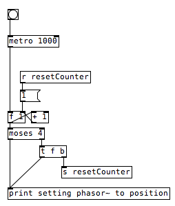
I experienced that i need some kind of sync-mechanism in order to keep the eight samples in sync while they are playing. So I gave the following a try:
I set the position of phasor~ using its right inlet with every whole beat (1,2,3,4) of my bpm-metronome. The current position is calculated in dependency of the current sample's length.
It works, but every time I set a new position to phasor~ I hear a popping noise in my speakers. So my approach is probably completely senseless, but I thought I ask you. Maybe you have a solution to my problem or an idea for another approach.
Attached, you find a pseudo-patch which symbolises what I am doing. Think of the print-object as the phasor~ object.
Thank you, Jakki
PseudoSync.pd
 posted in technical issues
prophet 3003 wavetable synth prototype
hi folks, thanks for the kind comments!
sure ill share the patch eventually but right now its an uncommented messy laboratory affair. best thing you can do right now is look at the patch image above which is quite self explanatory.
here is the vs rom in one wav file, scan this in 128 chunks of 128 samples and you have the single wave data.
harmonic aliasing is best described by acreil in the above mentioned blog post because thats where i got the idea from. the rest is trial and error and a lot of listening to integer combinations.
harmonic aliasing is actually my own term for what im trying to do. here is how i would describe it:
-
if you repeat 128 samples with a phasor at 128 hz (or 64/32/16/8/4/2) or any multiple of 128 your phasor restarts exactly at the beginning of the wave data and the aliasing frequencies generated by the steppyness of the data will follow the harmonic overtone series 1,2,3 etc. depending on the multiple.
-
if you introduce another prime divider ie. 3 as in 128 / 3 the phasor will line up with the sample data every 3rd sample and the osc will alias at the 3rd subharmonic frequency which will be somewhat more disharmonic than any overtone.
-
another way to look at it would be the pattern repetitions. at subdivision 5 the phasor starts at 5 different points in the sample data and its easy to imagine that the readout patterns are all slightly different ... but the whole thing cycles after 5 phasor rounds = 5th subharmonic..
-
if you subdivide 128 further with a higher prime ie. 563 you will get 562 different sounding samples until nr. 563 lines up again. get the idea?
this is all very easy to hear once you experiment with prime subdivisions and multiplications. just remember its all based on synching the data flow from the sample with the frequency of the index phasor. this will work with ANY sample data, the vs rom is just cool to use for vintage synth fans.
whats important for proper aliasing is that you use a simple [tabread] into the data without any interpolation like tabread4 or oversampling!
all the other elements in the synth like delay, waveshaper, sequencer follow the same rule as they are just repetition devices like the wavetable oscillator.
if you finally synch everything to the sample rate of your soundcard the voltages that hit your speakers will repeat in exact patterns. thats the idea of this synth: precision number repetition controlled by harmonic/disharmonic integer combinations ... just like the great 80s synths waldorf microwave or prophet vs.
 posted in output~
Problem loading libraries (iemguts)
Eighteen-year-old Shen Qiang says he soon thereafter began winning Canadian contests, and came in Canada in 2004. He will be a proud representative of the Canadian Olympic team this summer. While he didn't immigrate explicitly to further his table tennis career (he came with his family, who live in Toronto), he's happy with Table Tennis Canada's sports app, and is looking forward to the autumn opening of this new 24-hour training centre in Ottawa, so that he can work harder on his sport. Produced in northeast China, Shen first picked up a paddle at nine. He quit college to proceed to Harbin, a town 300 kilometers away, to train full-time and represent the province of Heilongjiang and had left home. The contest in China was extremely intense, '' he states. https://ok.ru/group/53953306755154/ The athletes trained five days a week, six hours a day; they were paid to train fulltime and compete, he says. "In China, it is very competitive because in the event you do not make results then you will be removed from the team, and if you don't have table tennis without a school, there is no future for you."
 posted in technical issues
[vphasor~] and [vphasor2~], subsample-accurate phasors
Hello everyone, long time no see.
I've been getting back into Pd lately and have been messing around with some granular stuff. A few years ago I posted a [vphasor.mmb~] abstraction that made the phase reset of [phasor~] sample-accurate using vanilla objects. Unfortunately, I'm finding that with pitch-synchronous granular synthesis, sample accuracy isn't accurate enough. There's still a little jitter that causes a little bit of noise. So I went ahead and made an external to fix this issue, and I know a lot of people have wanted this so I thought I'd share. ")
[vphasor~] acts just like [phasor~], except the phase resets with subsample accuracy at the moment the message is sent. I think it's about as accurate as Pd will allow, though I don't pretend to be an expert C programmer or know Pd's api that well. But it seems to be about as accurate as [vline~]. (Actually, I've found that [vline~] starts its ramp a sample early, which is some unexpected behavior.)
[vphasor2~] is [vphasor~] with an additional signal inlet. This inlet expects another positive-ramping phasor and is used for hard-syncing. When the phasor inlet gets a drop--as happens when a the phase cycle starts over--[vphasor2~] resets its phase to zero. It also does this with subsample accuracy by taking the last and first samples of the phase and estimating when it reset. That's why it needs a positive-ramping phasor as the input. If you try to hard-sync with a sine wave or something, it won't work.
As far as I can tell, everything is working, but let me know if you find a bug. I tried to document the code thoroughly as well.
The sources and helpfiles are included in the zip file. It uses the Makefile template, so just type "make" and it should compile.
vphasor.zip
 posted in extra~
siwtch/case in pd ? (IN VANILLA)
@phil123456 It's hard to tell with the picture.... but it looks as though sending the number to all of the [pd phaser-bank] objects and letting them decide how to "use" that number would be easiest.
If you make an abstraction of [pd phaser-bank] as maybe [phaser-bank] and then place that many times in the patch with a number argument........
[phaser-bank 1]
[phaser-bank 2]
[phaser-bank 3]
etc.
Then in [phaser-bank] you could use
[r number_being_sent]
|
[t b f]
| |
[$1<]
|
[do it $1 times]
to let the abstraction decide it's action...........
Does that make sense? it was posted in a hurry....
David.
 posted in patch~
Compiled external saying "couldn't create" when being added to PD
Greetings All
I'm having trouble getting my external to work, It compiles with 5 warnings
sineq.c:48: warning: unused variable ‘x’
sineq.c:49: warning: unused variable ‘in1’
sineq.c:50: warning: unused variable ‘in2’
sineq.c:51: warning: unused variable ‘in3’
sineq.c:52: warning: unused variable ‘in4’
It does a "make" successfully but I get this warning message
/usr/bin/ld: warning: cannot find entry symbol xport_dynamic; defaulting to 00000000000007f0
but when I try and add it in PD it says "couldn't create". I've looked at the pan~ tutorial and the d_osc.c file as recommended, which did help. I tried to take pieces from the two which I thought were applicable to my situation but I'm still having some issues.
Here's a link to the workflow (dropbox)
http://dl.dropbox.com/u/6576402/questions/pd/Sine_EQ_Diagram.jpg
Here's a link to the C code online (pastebin)
http://pastebin.com/9rK3szUE
My external is a reproduction of the sinewave equation with 4 inputs and one output my logic is to have 4 inlets one for the frequency,amplitude,phase and vertical offset and an output for the created signal. Granted this isn't the final equation but this will help me understand how to create the full equation once done. If you want to see the full equation I'll be using here's a link to it below. Basically it's a 1 second periodic signal with the sample rate at 44100 which the equation gives me control over the frequency,amplitude,phase and vertical offset.
Another question I have is what do I use for the t (time) for my final equation is that the t_sample object in PD? or do I need to create a for loop counting from 1-44100 for a 1 second 44100 sampled equation?
http://dl.dropbox.com/u/6576402/questions/eq1.txt
PS: I'm compiling on ubuntu 10.04 using gcc
 posted in technical issues
Problem with syncing audio loops
hey guys!
okay, I am using readanysf~ extension to open sound files. I created a looper abstraction.
Then I have created several loopers in a patch. Each looper has an inlet which allows to start playback and stop playback.
Let's say I have two samples: hihats and base drum. Both were recorded at 130 bpm and saved to wav files. In order to sync them on other software I would use something to trigger those files at the same time and they would be in perfect sync forever.
In this patch I've done the same thing - notice the play all button. So I load these two files into two loopers and then trigger them with play all. First 4-5 rounds loops are in sync, but then they begin to go out of sync.
The interesting thing is that if you load same file into different loopers and trigger them - they will NEVER go out of sync.
So I was wondering if I am missing something, maybe some inner workings of Pd which make audio files go out of sync.
Patch attached. Open TapeLoops16.pd
 posted in technical issues