hi, i have a long-term issue that i'd like to now get fixed. i'm using a 0...10hz osc~ as an amplitude modulator.
but whenever i get from 0.001 to 0 - there's an audible click. how can i avert this click?

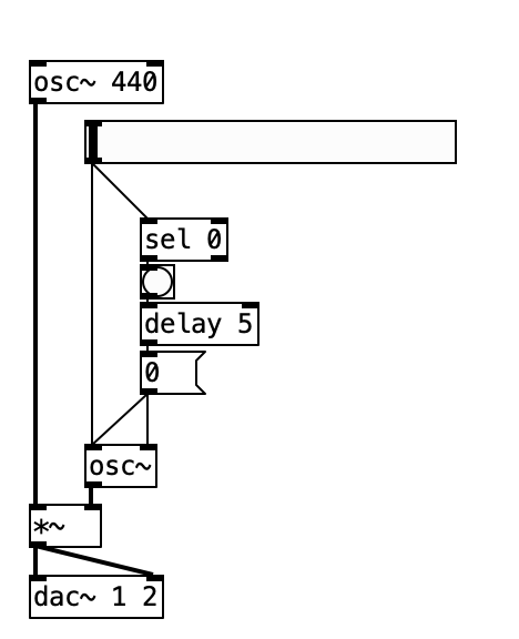
not sure if this image will help.
using 0..10hz osc~ as amplitude modulation, when i get to 0, there's an audible click
hi, i have a long-term issue that i'd like to now get fixed. i'm using a 0...10hz osc~ as an amplitude modulator.
but whenever i get from 0.001 to 0 - there's an audible click. how can i avert this click?

not sure if this image will help.
@esaruoho The image is not useful as you say.
The only [osc~] that I see seems to be set to 0Hz and have its phase reset 5ms after receiving data..... so maybe the phase reset causes the click as the [osc~] wave could be at any value when the phase is reset and a sudden jump in value is a click.
David.
@whale-av said:
@esaruoho The image is not useful as you say.
The only [osc~] that I see seems to be set to 0Hz and have its phase reset 5ms after receiving data..... so maybe the phase reset causes the click as the [osc~] wave could be at any value when the phase is reset and a sudden jump in value is a click.
David.
yep, that's what's happening. if i don't have the delay5 0( then the amplitude might be set to anything, so then i have to keep resetting it to zero multiple times until it's at the original volume. so hence the phase needs to be reset to 0.
here, maybe this'll help.
clicks when goes to 0.pd
i tried both hooking the 0..10hz osc to the first inlet of [*~] or the second inlet. both "goes to 0" result in an audible click.
how does one reset the phase so that the volume is at the original volume, please?
here's the attached script as a screenshot

@esaruoho when it gets to 0 frequency, use a [line~] going into the same inlet as the osc~ and ramp from
0 to the difference between the output value at the phase you want to set and the current output value (get w/ [snapshot~]). (so if current output of the osc~ is -0.25 and will be 1 when the phase gets set, ramp from 0 to 1,25).
then after the ramp is done, set the osc~ phase and reset the line~ to 0 at the same time.
this technique is called 'switch and ramp' and is explained by miller in his book http://msp.ucsd.edu/techniques/v0.11/book-html/node63.html
(here I did it in reverse by ramping first and then switching, but you could also simply add the discontinuity when you change the phase and ramp to 0. that would work to eliminate the discontinuity as well, but in that case the artifact might be more prominent bc the frequency is higher)
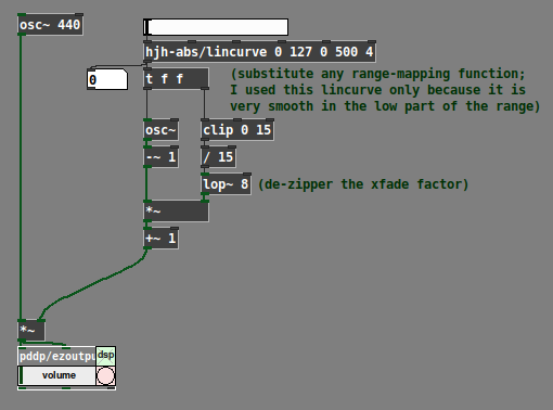
I was going to suggest that, at very low amplitude-modulation frequencies, you can crossfade between the original and the amplitude-modulated wave.
Let's say, for AM frequency >= 15, you want sig * mod, and between 0 and 15, you want a linear fade between sig vs sig * mod. So x = clip(x, 0, 15) / 15.
sig * (1 - x) + (sig * mod) * x
sig - sig*x + sig*mod*x  // all terms have a 'sig' factor
sig * (1 - x + mod*x)
sig * (mod*x - x + 1)
sig * (x * (mod-1) + 1)

[lincurve] isn't important -- it's an abstraction from my library, which I used for testing only because it makes it easy to ramp slowly up from 0, but faster as you get closer to the other end of the range. You can use any range mapping function you want.
hjh
Oops! Looks like something went wrong!