enzien heavy java script example
i tried to run the examples: https://github.com/enzienaudio/examples/tree/master/javascript
http://libpd.handmadeproductions.de/
http://libpd2.handmadeproductions.de/
the chip example works fine, but the sampleplayer gives me this error message when i start to play the sample:
warning: a problem occurred in builtin C++ name demangling; build with  -s DEMANGLE_SUPPORT=1  to link in libcxxabi demangling
42samplePlayerLib.min.js:24639 Uncaught abort() at Error
    at jsStackTrace (http://libpd2.handmadeproductions.de/js/samplePlayerLib.min.js:1351:13)
    at stackTrace (http://libpd2.handmadeproductions.de/js/samplePlayerLib.min.js:1368:22)
    at Object.abort (http://libpd2.handmadeproductions.de/js/samplePlayerLib.min.js:24633:44)
    at _abort (http://libpd2.handmadeproductions.de/js/samplePlayerLib.min.js:1923:22)
    at _malloc (http://libpd2.handmadeproductions.de/js/samplePlayerLib.min.js:19069:9)
    at __ZL26mq_getOrCreateNodeFromPoolP14HvMessageQueue [mq_getOrCreateNodeFromPool(HvMessageQueue?*)] (http://libpd2.handmadeproductions.de/js/samplePlayerLib.min.js:13201:10)
    at _mq_addMessageByTimestamp (http://libpd2.handmadeproductions.de/js/samplePlayerLib.min.js:12830:8)
    at Array.__ZN18Heavy_samplePlayer26scheduleMessageForReceiverEjP9HvMessage [Heavy_samplePlayer::scheduleMessageForReceiver(unsigned int, HvMessage?*)] (http://libpd2.handmadeproductions.de/js/samplePlayerLib.min.js:6949:4)
    at Array.__ZN18Heavy_samplePlayer7processEPPfS1_i [Heavy_samplePlayer::process?S(float**)] (http://libpd2.handmadeproductions.de/js/samplePlayerLib.min.js:7425:33)
    at Array.__ZN18Heavy_samplePlayer13processInlineEPfS0_i [Heavy_samplePlayer::processInline?S(float*)] (http://libpd2.handmadeproductions.de/js/samplePlayerLib.min.js:7877:41)
Was it possible for anybody to run the second example or knows how to fix the error?
 posted in libpd / webpd
Ofelia images -> variables
I'm starting to look at ofelia (excited about this, actually  ).
).
But I find myself confused about what images and variables.
I managed to make my own patch doing:
- [ofSetup] -> [load ...( -> ofImage name
- [ofDraw] -> [ofImage name ...]
... and it draws the picture properly.
But I saw other examples using the images within an [ofelia f] object -- for example, the pointillism example loads the image into [ofImage $0-img] and then has [ofDraw] -> [ofRequire $0-img] -> ... -> [ofelia f; local img, m = a[1].image, a[2]; ...].
So I made [ofDraw] -> [ofRequire name] -> [ofelia f; ...] and now I don't know what to do.
name:draw(...) just throws a lot of nil reference errors into the console window... but clearly example files are able to use images within [ofelia f]...? If I have "require"d name, then I suppose "name" should be available somehow?
What is the relationship between the [ofRequire] objects and the implicit a argument?
Apologies if this is supposed to be obvious. I went looking for a tutorial series and I didn't find anything, so I'm attempting to infer first principles from examples. That can take you only so far.
Thanks,
hjh
 posted in pixel#
pduino for Vanilla or how to control arduino outputs from PD
[arduino] is the Pduino abstraction that communicates with Arduino via Firmata, and I think it's vanilla. Any way, if all you want is to control Arduino pins from Pd, you just need to send the correct bytes to Arduino through [comport].
I've written a tutorial on the communication between Pd and Arduino which you can find here, under "Tutorials", it's called "Arduino for Pd'ers".
After I wrote the tutorial I also wrote some abstractions to facilitate this communication, which are not used in the tutorial. You can get them here. Though, these are meant to receive data from the Arduino, not send. Sending data is covered in the tutorial.
 posted in technical issues
Easy resonant lp filter?
I actually meant to show this example where you can have a look at the frequency response of [vcf~] : https://github.com/porres/Live-Electronic-Music-Tutorial/blob/master/Examples/Vol.2/Part.05-Filters(Basic)/22-Filters.types/2.Filter.Types/2.Resonant/2.Bandpass/2.[vcf~].pd
why the help patch doesn't claim that it's lowpass
cause miller seems to consider it a lowpass, but I wouldn't consider it a proper one. You can see in that example that you have a constant zero dB, which is not how lowpass filters usually work.
it's "like [bp~]" and refers to center frequency, but it seems to attenuate high frequencies
more sharply than low, so I'm not sure if it really is bandpass, classically, or not.
yeah, it does attenuate more the high frequencies, the previous example to the one I posted above shows that too. I wouldn't consider it a proper bandpass as well.
Both [bp~] and [vcf~] are just pretty cheap filters. You'd need a biquad (with 2 poles and 2 zeros) to make a proper bandpass and a lowpass.
 posted in technical issues
getting started with pure data: any book, pdf, tutorial recommendations?
@emens ; https://github.com/porres/Live-Electronic-Music-Tutorial/releases
"Live Electronic Music Tutorial with examples in Pure Data and the ELSE Library By Alexandre Torres Porres
This tutorial presents theory and practice of Live Electronics topics without any prerequisite. It's aimed at newbies, dummies, enthusiasts and also experts. Pure Data is adopted in the examples for its accessibility and for being a powerful didactic tool. Nonetheless, this work relies heavily in the ELSE library for Pure Data, also developed by Alexandre Torres Porres, the author of this tutorial => check about the ELSE library here: https://github.com/porres/pd-else"
posted in tutorials
ofelia GLSL shader loader
I made a GLSL shader loader with ofelia. Most examples from http://glslsandbox.com work without modifications (like the examples that i included). While the examples from https://www.shadertoy.com do not work out of the box.
A lot of other shader examples do not work at all (perhaps because I did not modify them right?).
Or is it possibly because of the wrong GLSL version?
What I am searching for are mainly video effects, especially a video delay (something like that: ).
It would be great if there is already a shader like that which works with ofelia.
One question: Somehow Pure Data complains about a missing .vert file, but it is still working fine without. Can I make something like this:
void main()
{
    gl_TexCoord[0] = gl_TextureMatrix[0]*gl_MultiTexCoord0;
    gl_Position = gl_ModelViewProjectionMatrix*gl_Vertex;
}
as a .vert file dummy? At least it seems to work.
I set this GLSL variables in ofelia (because they fit to the sandbox examples):
uniform float time;
uniform vec2 mouse;
uniform vec2 resolution;
posted in abstract~
Live Electronis Tutorial by Porres in English (& ELSE beta 12 released)
Hi, I had to make a quick update to both my Live Electronics Tutorial and ELSE library. The new object [hann~] is now fixed and the FFT examples now work! I also added a new object to ELSE: [comb.filt~], this object is also part of the tutorial and I ended up revising the filters/reverb section of my tutorial as well and included a new section on resonators. See: https://github.com/porres/Live-Electronics-Tutorial
It already relies on the (still in test phase) 0.49-0 release of Pure Data (though 99% will work in 48). It also relies heavily and extensively in the ELSE library, and you can already find the last release (Beta 13) on deken (pd => Help => Find Externals). See https://github.com/porres/pd-else/releases/tag/v1.0-beta13 for details and more binaries not yet in deken. I've made ELSE to not rely on 0.49 yet, but next release will for sure.
cheers
posted in news
Live Electronis Tutorial by Porres in English (& ELSE beta 12 released)
Hi, two related announcements!
I've Finished translating the vol. 2 of my Live Electronics Tutorial to English, with now 323 examples! https://github.com/porres/Live-Electronics-Tutorial - It already relies on the (still in test phase) 0.49-0 release of Pure Data (though 99% will work in 48). Anyway, vol. 2 is where things gets a little serious... there's FFT stuff and I really like my take on filters (folder "29").
I hope this becomes a relevant tutorial for Pd. Let me know what you think. Next plan is to write a book where these are the examples. This is a very special announcement for me as I've been working on this for 10 years now and I'm happy to make it available in english. Not only that, but to finally port it out of Pd Extended and into Vanilla!
Porting to Vanilla relies heavily and extensively in the ELSE library, and this is where most of my work has been put recently, in order to port this out of Extended. This brings us to the next announcement: I have a new release that it relies on, Beta 12! Find it on deken (pd => Help => Find Externals). See https://github.com/porres/pd-else/releases/tag/v1.0-beta12 for details. Newer additions to the tutorial now depend on developments of ELSE.
The last release was a couple of weeks ago but I'm really proud of the advancements I made. I'd like to highlight the additions to [envgen~], you really should check it out, it's a very powerful and versatile envelope generator. I still wanna allow for exponential curves, maybe next time. This release of ELSE also already relies on Pd 0.49, but works for the most part with 0.48.
cheers
posted in news
ofelia v1.0.7 released
Hi, ofelia v1.0.7 is now available.
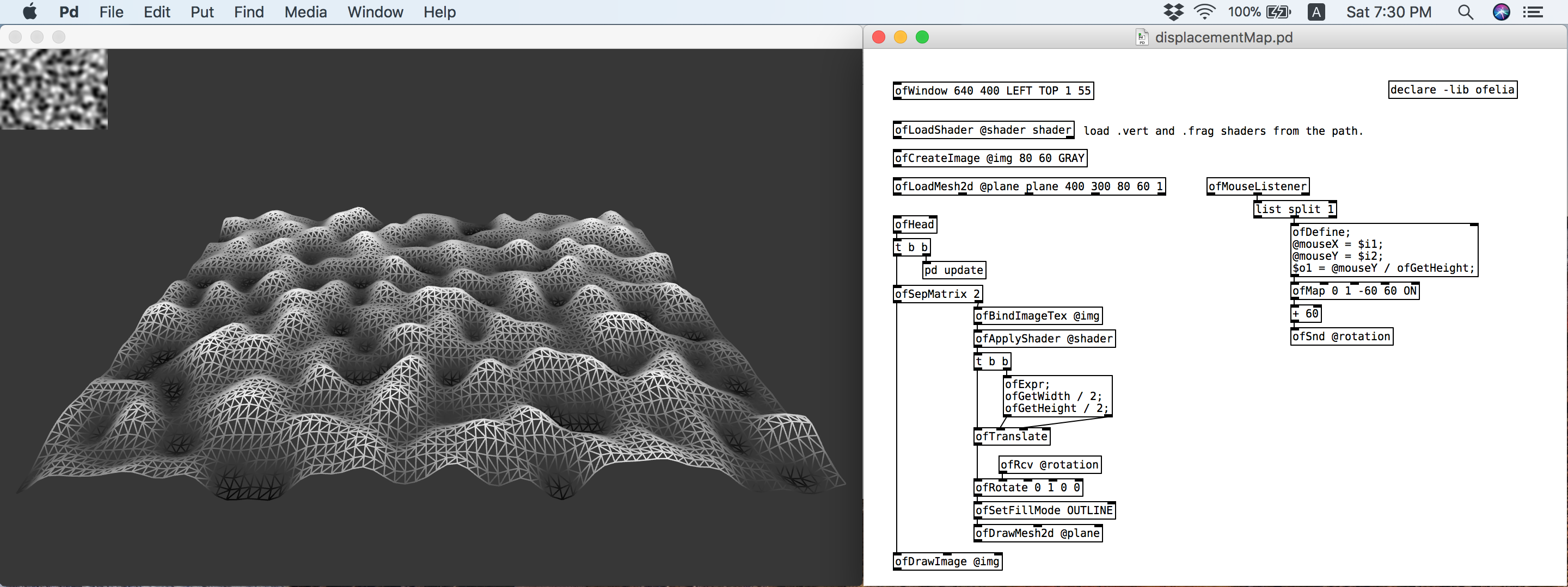
This version includes GLSL shader loader.
GLSL is a C/C++ similar high level programming language for several parts of the graphic card. With GLSL you can code short programs called shaders which are executed on the GPU.
Please try out the examples in the "ofelia/examples/shader" directory.
You can see the full list of shader objects from "ofelia/help-intro.pd".
Changes:
- added primMode argument to cone, cylinder, plane, sphere mesh command
- added ofShader related objects and help files
- added shader examples to the "examples/shader" directory
- added draggableShapes example to the "examples/input" directory
Upcoming features:
- Video player and grabber
- SVG loader
- GUI abstractions
More info about ofelia: https://github.com/cuinjune/ofxOfelia
Cheers!
 posted in news
Build a MIDI controller with the Arduino, Firmata and Pure Data
Time to start contributing some knowledge back to the wonderful world that is the internet; today, a step by step nice and easy tutorial on getting started to building your own MIDI controllers with the arduino.
When researching for my ableton controller project, I didn’t find much out there about using firmata on an arduino to send data to software. The standard approach just seemed to be create the code in the arduino language, upload it to your board and hack one of those MIDI to USB cables as a bodge job way of getting the MIDI out of the arduino.
So why firmata and pure data? Well the whole idea of firmata is that you flash it to your arduino, and it throws out serial about whats going on with the arduino inputs and outputs, then you decide how the software treats the readings coming in and going out.
Theory out the way, lets build some controllers. You’ll need a few things…
HARDWARE:
An arduino and something to wire into it (for this i’ll be using a pot)
A USB cable for your arduino
SOFTWARE:
Arduino – http://arduino.cc/en/Main/Software
Pure Data – http://puredata.info/downloads
Firmata – http://at.or.at/hans/pd/objects.html#pduino
Something to patch your new controller into; like Reason or Ableton Live
- SETTING UP FIRMATA AND PURE DATA
Install Pure Data and create a folder to store all your patches somewhere. Unzip Firmata and add the files ‘arduino.pd’, ‘arduino-test.pd’ and ‘arduino-help.pd’ to your new Pure Data folder. The ‘arduino.pd’ file is the object that we use in PD for opening up communication with your arduino and routing it to PD. Done? Awesome, your software is almost set up.
- FLASHING FIRMATA TO YOUR ARDUINO
Install the latest version of arduino and open it up. Connect your arduino with the USB cable to your laptop (i’m using a macbook for this by the way). In the example patches, open up “Standard Firmata”, select your board (im using an arduino mega), and your serial port (look for tty.usbserial for use with a USB cable). Then compile and hit the upload button and your arduino is now ready to use firmata and communicate with Pure Data!
- WIRING UP A POT
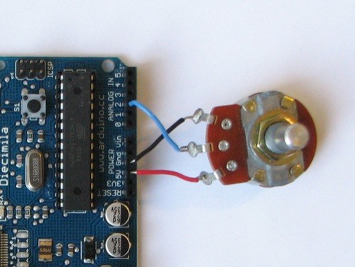
Potentiometers are cool, and theres a great arduino tutorial of how to wire one up here: http://www.arduino.cc/en/Tutorial/Potentiometer
Basically, all you need to know is that there are three pins; your two outer pins govern voltage flow across the pot, meaning one has to be 5V and the other has to be ground. It doesn’t matter which, but your 5v pin is going to be where your pot reads maximum, so convention dictates this should be the right hand pin. The center pin needs to be connected to an analog in on the arduino and will read the value of the pot as it sweeps from ground (0v) to 5v.
All wired up? Plug it into your laptop and open Pure Data, we’re ready to get things talking.
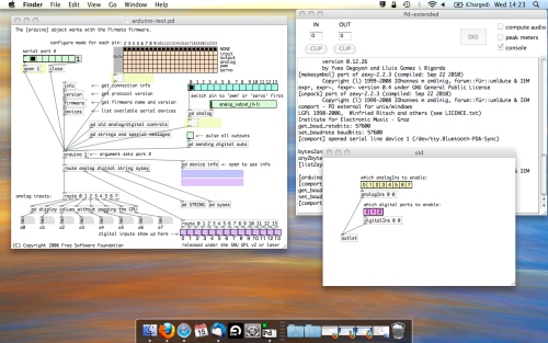
- SETTING UP OUR PATCH
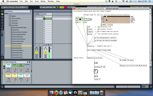
Open the example “arduino-test.pd” Pure Data patch you copied over earlier. It should look like this one…
The test patch has everything we need to open a connection and enable pins. Firstly, lets delete a bunch of stuff and make our window a bit bigger. Hit Command + E to enter edit mode in Pure Data.
Ok a quick explaination; the key component here is the ‘arduino’ object. This is being drawn from the file you copied in earlier, and is what communicated with your arduino. Here we can do everything to control the arduino from opening a connection, to receiving data.
The large grid allows us to set the mode of each pin on the arduino. Remember pins 0 and 1 are reserved for Rx and Tx. I’m using analog pin 4 for this demo, so I’ve set my pin mode for pin 4 to ‘analog’.
Now we can plug our arduino in and get a reading from the potentiometer.
- ARDUINO INTO PURE DATA
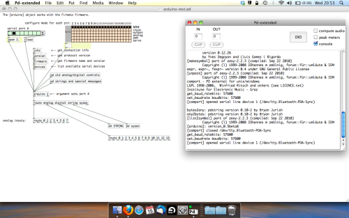
With your arduino plugged in, hit command and E to bring us out of edit mode. In our patch, click on ‘Devices’ above the arduino object and open up the pure data terminal. (That other thing that loads with PD that has all the scary code in)
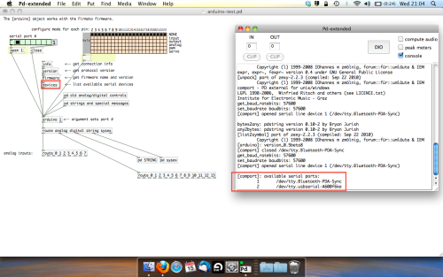
The “Devices” message connected to the arduino object pings your computer to find what devices are connected and on what serial ports. Since we’re using a USB cable to connect our arduino, we’re looking for something with ‘usbserial’ in it, in this case; port 2.
Select the relevent port in the green box at the top (remember the first box is ‘0’, second is ‘1’ and so forth) and hit ‘Open’ to establish a connection. Check the terminal to see if the connection was sucessful.

Now lets check we’re getting something in. Create a number box (Command + 3) and connect it to the relevent pin on the ‘Route analog’ box at the bottom. In this case, pin 4.
One more thing; if you’re not getting any readings in, you’ll need to click on ‘pd old analog/digital controls’ and enable your pins here too. What I tend to do in my patches is just not include the large grid but make my own ‘old pd’ controls custom to what i’m enabling/disabling to save space.
Here’s what the ‘old analog/digital controls’ subpatch looks like (pin 4 enabled)…
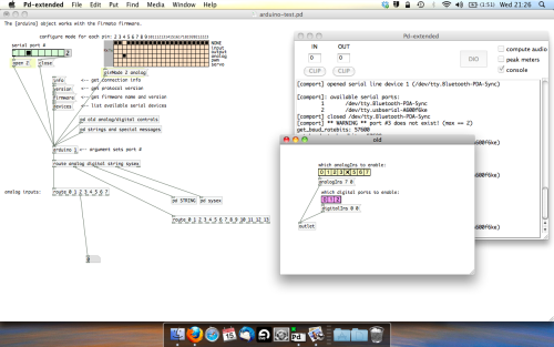
Come out of edit mode and check that you’ve got readings. If so congratulations! If not, troubleshoot, start with making sure your usb connection is opened, make sure all the correct pins are enabled (remember you’re counting from 0 not 1 on most of these buttons in PD, it’s just the way computers work).
- SCALING READINGS TO MIDI
So we’ve got a reading and chances are it’s to 3 decimal places between 0 to 1. No problem, create a new object (Command + 1) and type “autoscale 0 127”. This allows us to scale the input to a min and max value, in this case 0 to 127 of MIDI. Next, lets get things looking nice, create a new object and type “knob”. Connect this AFTER the autoscale object. (the knob is default set to read inputs from 0 to 127. Then create another number to display the scaled MIDI data coming out, and finally a new object and type “ctlout 1”.
It should look something like this…
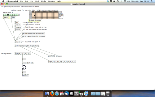
The second box should be outputing values from 0 – 127 now, and the knob giving a visual representation of your potentiometer.
Now lets patch it into ableton…
- PURE DATA TO ABLETON LIVE
Firstly, you’ll need to set up your macs IAC driver if you’ve not done this. Basically you’ll need to go into Audio/MIDI preferences and enable your IAC driver. Then create a new input and output. One for input to DAW and one for output from DAW. Google around for a tutorial on this, its really simple, a 30 second job.
After you’ve set up your IAC driver, go back to PD and go to preferences > MIDI Settings, and connect your IAC driver.
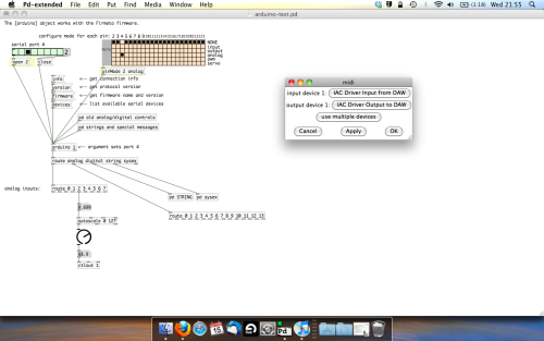
Open ableton and go to its MIDI preferences. Create a device listing for your IAC driver and enable its ins and outs into ableton like so…
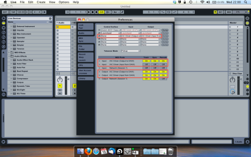
And thats it! Create an instrument and try to assign something! I’ve got it controlling the brightness of a bass sound here.
Shout out for Facu who requested this tutorial. Hopefully it’ll help some of you looking to get into this stuff and start building things but with no idea where to start.
 posted in tutorials