Use the message read -resize
Hi there !
I'm using the message [read resize $1 Audio] just after an Openpanel object to read a sound in an array named Audio with the object tabread4~ Audio.
It's working great and I want to use my patch as an abstraction but I've issue with the use of $0.
I 've named my array $0-Audio, I've writen tabread4~ $0-Audio and [read -resize $1 $0-Audio]. Pd send me "0-Audio : no such table".
I don't understand what I have to write in the message [read -resize] to solve the problem.
If someone could help me for this, it will be nice.
I'm new here, I've created a account just to ask this because I've not found a real response about this in particular.
 posted in technical issues
Using two identical USB soundcards in Pure Data on Raspberry PI (raspbian stretch lite)
I needed a cheap way to get audio in/out of PD on RPI so I bought a couple of these tiny white USB soundcards with line out and mic input (less than a dollar each) as I'd read here that they work with RPI.
http://raspberrypimaker.com/cheap-quality-audio-raspberry-pi/
They work ( RPI1, model B ), and the output is decent, but there's an annoying high-pitched hum originating from the mic input that is probably due to the proximity of the ADC to the DAC on the unit.
I though I'd solve it by using one card for the mic input and another for the output.
As far as I understand, this should be possible using the -audiodevout options in the pd command line (or the gui settings). Neither of these have worked for me. Specifically, pd outputs from the same card, even though I specify the correct device number in =audiodev or -audiodevout. Both cards work well when used alone.
I'm guessing the problem is that pd sees the two devices (or at least refers to them) as identical. This is the output from pd -nogui -alsa -listdev
audio output devices:
- bcm2835 ALSA (hardware)
- bcm2835 ALSA (plug-in)
- USB PnP Sound Device (hardware)
- USB PnP Sound Device (plug-in)
- USB PnP Sound Device (hardware)
- USB PnP Sound Device (plug-in)
So even though one card is here listed as device 3-4, and the other as 5-6, pd always plays audio from the same card when given any of the numbers in -audiodev. / -audiodevout.
I'm very inexperienced with linux in general, but it seems that since alsa does give these two devices a unique name/number, pd. should be able to distinguish between them. This is the output from alsa -l
**** List of PLAYBACK Hardware Devices ****
card 0: ALSA [bcm2835 ALSA], device 0: bcm2835 ALSA [bcm2835 ALSA]
Subdevices: 7/7
Subdevice #0: subdevice #0
Subdevice #1: subdevice #1
Subdevice #2: subdevice #2
Subdevice #3: subdevice #3
Subdevice #4: subdevice #4
Subdevice #5: subdevice #5
Subdevice #6: subdevice #6
card 0: ALSA [bcm2835 ALSA], device 1: bcm2835 ALSA [bcm2835 IEC958/HDMI]
Subdevices: 1/1
Subdevice #0: subdevice #0
card 1: Device [USB PnP Sound Device], device 0: USB Audio [USB Audio]
Subdevices: 1/1
Subdevice #0: subdevice #0
card 2: Device_1 [USB PnP Sound Device], device 0: USB Audio [USB Audio]
Subdevices: 1/1
Subdevice #0: subdevice #0
Any advice would be greatly appreciated!
 posted in technical issues
Audio Settings for multichannel with MOTU 828 mk3
Hi Matthieu,
I see your post is a little bit old but I'm experiencing the exact same problem now with my setup.
I'm using a Windows 7 machine with a MOTU 828x sound card connected via USB to the PC and Pd 0.48.1 vanilla.
Here what I've done:
- I've checked the "Use Stereo Pairs for Windows Audio" inside the "MOTU Audio Console";

- opened PD and selected "standard MMIO" as driver from the "Media" menù;
- now here's the list of outputs as it appears from the drop-down menu of "Media/Audio Setting.../Output device":
- MOTU Analog 3-4
- Loudspeakers (devide High ...
- MOTU Main-Out 1-2
- MOTU ADAT optical A 3-4
- Digital Output MOTU Audio
- MOTU ADAT optical A 1-2
- MOTU Analog 1-2
- MOTU ADAT optical A 7-8
- MOTU ADAT optical B 3-4
- MOTU Analog 7-8
- MOTU Analog 5-6
- Digital Output
- MOTU SPDIF 1-2
- MOTU ADAT optical B 1-2
- MOTU ADAT optical A 5-6
- MOTU Phones 1-2
As you see this list is pretty messed up and the names of logical consecutive output channels are not consequential. I would like to have 8 analog outputs from my MOTU so I selected the first item on the list (MOTU analog 3-4) then specified a total of 22 channels.
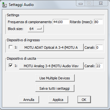
I'm obliged to set 22 as the total number of output channels because in my list MOTU Analog 5-6 are the last analog elements present. Because items in the list represent pairs of channels, this item corresponds to logical channel 21 and 22.
- Then I created the dac object this way:
[dac~ 13 14 1 2 21 22 19 20]
Here's an image
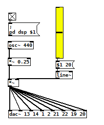
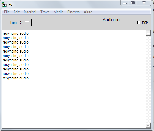
This way I'm able to hear sound on all analog outputs of the MOTU even if I'm experiencing variuous 'clicks' and a series of "resyncing audio" messages inside the PD console...
I confess, this method is the only way I'm able to make this setup work but it seems to me to be pretty messy and not intuitive at all.
What seems to be even worse is that analog audio outputs inside the device list seems to change their order at each computer restart, so every time I have to restart from scratch.
- Is there some easier solution to this problem?
- Maybe a preference file I can create for PD to load at each startup containing all these settings?
- or there may be a way to programmatically select correct "analog outputs" from the device list in my patch (even if string parsing doesn't seem to be so easy in PD to me).
- Would launching PD from console, maybe from an ad-hoc script, solve the problem?
Thank you so much for your support
M
 posted in technical issues
Build a MIDI controller with the Arduino, Firmata and Pure Data
Time to start contributing some knowledge back to the wonderful world that is the internet; today, a step by step nice and easy tutorial on getting started to building your own MIDI controllers with the arduino.
When researching for my ableton controller project, I didn’t find much out there about using firmata on an arduino to send data to software. The standard approach just seemed to be create the code in the arduino language, upload it to your board and hack one of those MIDI to USB cables as a bodge job way of getting the MIDI out of the arduino.
So why firmata and pure data? Well the whole idea of firmata is that you flash it to your arduino, and it throws out serial about whats going on with the arduino inputs and outputs, then you decide how the software treats the readings coming in and going out.
Theory out the way, lets build some controllers. You’ll need a few things…
HARDWARE:
An arduino and something to wire into it (for this i’ll be using a pot)
A USB cable for your arduino
SOFTWARE:
Arduino – http://arduino.cc/en/Main/Software
Pure Data – http://puredata.info/downloads
Firmata – http://at.or.at/hans/pd/objects.html#pduino
Something to patch your new controller into; like Reason or Ableton Live
- SETTING UP FIRMATA AND PURE DATA
Install Pure Data and create a folder to store all your patches somewhere. Unzip Firmata and add the files ‘arduino.pd’, ‘arduino-test.pd’ and ‘arduino-help.pd’ to your new Pure Data folder. The ‘arduino.pd’ file is the object that we use in PD for opening up communication with your arduino and routing it to PD. Done? Awesome, your software is almost set up.
- FLASHING FIRMATA TO YOUR ARDUINO
Install the latest version of arduino and open it up. Connect your arduino with the USB cable to your laptop (i’m using a macbook for this by the way). In the example patches, open up “Standard Firmata”, select your board (im using an arduino mega), and your serial port (look for tty.usbserial for use with a USB cable). Then compile and hit the upload button and your arduino is now ready to use firmata and communicate with Pure Data!
- WIRING UP A POT
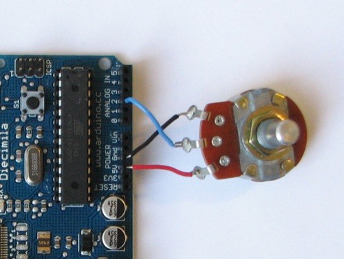
Potentiometers are cool, and theres a great arduino tutorial of how to wire one up here: http://www.arduino.cc/en/Tutorial/Potentiometer
Basically, all you need to know is that there are three pins; your two outer pins govern voltage flow across the pot, meaning one has to be 5V and the other has to be ground. It doesn’t matter which, but your 5v pin is going to be where your pot reads maximum, so convention dictates this should be the right hand pin. The center pin needs to be connected to an analog in on the arduino and will read the value of the pot as it sweeps from ground (0v) to 5v.
All wired up? Plug it into your laptop and open Pure Data, we’re ready to get things talking.
- SETTING UP OUR PATCH
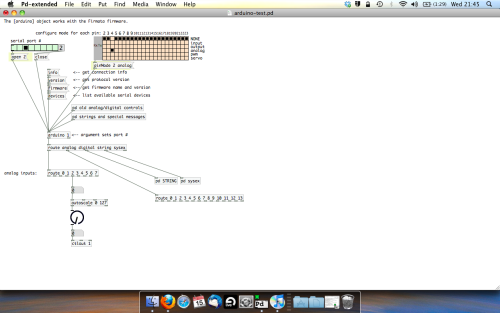
Open the example “arduino-test.pd” Pure Data patch you copied over earlier. It should look like this one…
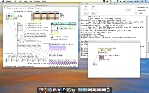
The test patch has everything we need to open a connection and enable pins. Firstly, lets delete a bunch of stuff and make our window a bit bigger. Hit Command + E to enter edit mode in Pure Data.
Ok a quick explaination; the key component here is the ‘arduino’ object. This is being drawn from the file you copied in earlier, and is what communicated with your arduino. Here we can do everything to control the arduino from opening a connection, to receiving data.
The large grid allows us to set the mode of each pin on the arduino. Remember pins 0 and 1 are reserved for Rx and Tx. I’m using analog pin 4 for this demo, so I’ve set my pin mode for pin 4 to ‘analog’.
Now we can plug our arduino in and get a reading from the potentiometer.
- ARDUINO INTO PURE DATA
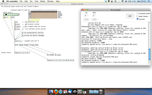
With your arduino plugged in, hit command and E to bring us out of edit mode. In our patch, click on ‘Devices’ above the arduino object and open up the pure data terminal. (That other thing that loads with PD that has all the scary code in)
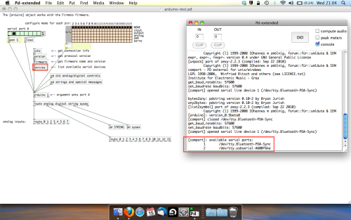
The “Devices” message connected to the arduino object pings your computer to find what devices are connected and on what serial ports. Since we’re using a USB cable to connect our arduino, we’re looking for something with ‘usbserial’ in it, in this case; port 2.
Select the relevent port in the green box at the top (remember the first box is ‘0’, second is ‘1’ and so forth) and hit ‘Open’ to establish a connection. Check the terminal to see if the connection was sucessful.

Now lets check we’re getting something in. Create a number box (Command + 3) and connect it to the relevent pin on the ‘Route analog’ box at the bottom. In this case, pin 4.
One more thing; if you’re not getting any readings in, you’ll need to click on ‘pd old analog/digital controls’ and enable your pins here too. What I tend to do in my patches is just not include the large grid but make my own ‘old pd’ controls custom to what i’m enabling/disabling to save space.
Here’s what the ‘old analog/digital controls’ subpatch looks like (pin 4 enabled)…
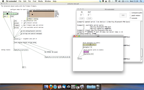
Come out of edit mode and check that you’ve got readings. If so congratulations! If not, troubleshoot, start with making sure your usb connection is opened, make sure all the correct pins are enabled (remember you’re counting from 0 not 1 on most of these buttons in PD, it’s just the way computers work).
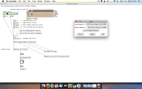
- SCALING READINGS TO MIDI
So we’ve got a reading and chances are it’s to 3 decimal places between 0 to 1. No problem, create a new object (Command + 1) and type “autoscale 0 127”. This allows us to scale the input to a min and max value, in this case 0 to 127 of MIDI. Next, lets get things looking nice, create a new object and type “knob”. Connect this AFTER the autoscale object. (the knob is default set to read inputs from 0 to 127. Then create another number to display the scaled MIDI data coming out, and finally a new object and type “ctlout 1”.
It should look something like this…
The second box should be outputing values from 0 – 127 now, and the knob giving a visual representation of your potentiometer.
Now lets patch it into ableton…
- PURE DATA TO ABLETON LIVE
Firstly, you’ll need to set up your macs IAC driver if you’ve not done this. Basically you’ll need to go into Audio/MIDI preferences and enable your IAC driver. Then create a new input and output. One for input to DAW and one for output from DAW. Google around for a tutorial on this, its really simple, a 30 second job.
After you’ve set up your IAC driver, go back to PD and go to preferences > MIDI Settings, and connect your IAC driver.
Open ableton and go to its MIDI preferences. Create a device listing for your IAC driver and enable its ins and outs into ableton like so…
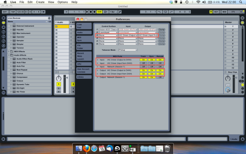
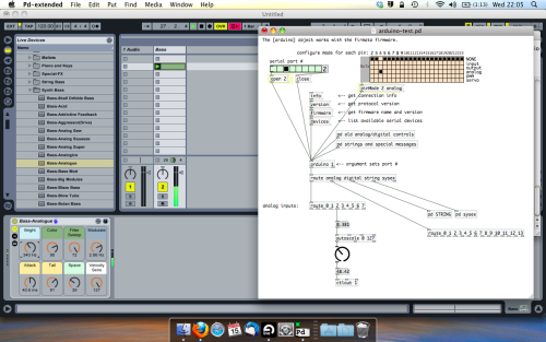
And thats it! Create an instrument and try to assign something! I’ve got it controlling the brightness of a bass sound here.
Shout out for Facu who requested this tutorial. Hopefully it’ll help some of you looking to get into this stuff and start building things but with no idea where to start.
 posted in tutorials
Ubuntu - Browsers and Puredata wont share audio output device. [SOLVED]
I found this solution and it worked ")
@sdaau_ml said:
Sorry to necro this thread, but I finally found out how to run PureData under Pulseaudio (which otherwise results with "ALSA output error (snd_pcm_open): Device or resource busy").
First of all, run:
pd -alsa -listdevPD will start, and in the message window you'll see:
audio input devices:
1. HDA Intel PCH (hardware)
2. HDA Intel PCH (plug-in)
audio output devices:
1. HDA Intel PCH (hardware)
2. HDA Intel PCH (plug-in)
API number 1

no midi input devices found
no midi output devices found
... or something similar.
Now, let's add the
pulseALSA device, and run-listdevagain:pd -alsa -alsaadd pulse -listdevThe output is now:
audio input devices:
1. HDA Intel PCH (hardware)
2. HDA Intel PCH (plug-in)
3. pulse
audio output devices:
1. HDA Intel PCH (hardware)
2. HDA Intel PCH (plug-in)
3. pulse
API number 1

no midi input devices found
no midi output devices found
Notice, how from the original two ALSA devices, now we got three - where the third one is
pulse!Now, the only thing we want to do, is that at startup (so, via the command line), we set
pdto run in ALSA mode, we add thepulseALSA device, and then we choose the third (3) device (which is to say,pulse) as the audio output device - and the command line argument for that inpdis-audiooutdev:pd -alsa -alsaadd pulse -audiooutdev 3 ~/Desktop/mypatch.pdYup, now when you enable DSP, the patch
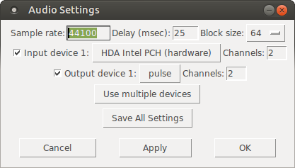
mypatch.pdshould play through Pulseaudio, which means it will play (and mix) with other applications that may be playing sound at the time! You can confirm that the correct output device has been selected from the command line, if you open Media/Audio Settings... oncepdstarts:
As the screenshot shows, now "Output device 1" is set to "pulse", which is what we needed.
Hope this helps someone!
EDIT: I had also done changes to
/etc/pulse/default.paas per https://wiki.archlinux.org/index.php/PulseAudio#ALSA.2Fdmix_without_grabbing_hardware_device beforehand, not sure whether that makes a difference or not (in any case, trying to adddmixas a PD device and playing through it, doesn't work on my Ubuntu 14.04)
 posted in technical issues
ALSA output error (snd\_pcm\_open) Device or resource busy
Sorry to necro this thread, but I finally found out how to run PureData under Pulseaudio (which otherwise results with "ALSA output error (snd_pcm_open): Device or resource busy").
First of all, run:
pd -alsa -listdev
PD will start, and in the message window you'll see:
audio input devices:
1. HDA Intel PCH (hardware)
2. HDA Intel PCH (plug-in)
audio output devices:
1. HDA Intel PCH (hardware)
2. HDA Intel PCH (plug-in)
API number 1

no midi input devices found
no midi output devices found
... or something similar.
Now, let's add the pulse ALSA device, and run -listdev again:
pd -alsa -alsaadd pulse -listdev
The output is now:
audio input devices:
1. HDA Intel PCH (hardware)
2. HDA Intel PCH (plug-in)
3. pulse
audio output devices:
1. HDA Intel PCH (hardware)
2. HDA Intel PCH (plug-in)
3. pulse
API number 1

no midi input devices found
no midi output devices found
Notice, how from the original two ALSA devices, now we got three - where the third one is pulse!
Now, the only thing we want to do, is that at startup (so, via the command line), we set pd to run in ALSA mode, we add the pulse ALSA device, and then we choose the third (3) device (which is to say, pulse) as the audio output device - and the command line argument for that in pd is -audiooutdev:
pd -alsa -alsaadd pulse -audiooutdev 3 ~/Desktop/mypatch.pd
Yup, now when you enable DSP, the patch mypatch.pd should play through Pulseaudio, which means it will play (and mix) with other applications that may be playing sound at the time! You can confirm that the correct output device has been selected from the command line, if you open Media/Audio Settings... once pd starts:
As the screenshot shows, now "Output device 1" is set to "pulse", which is what we needed.
Hope this helps someone!
EDIT: I had also done changes to /etc/pulse/default.pa as per https://wiki.archlinux.org/index.php/PulseAudio#ALSA.2Fdmix_without_grabbing_hardware_device beforehand, not sure whether that makes a difference or not (in any case, trying to add dmix as a PD device and playing through it, doesn't work on my Ubuntu 14.04)
 posted in technical issues
Bela ultra-low-latency embedded audio-sensor platform
Hi everyone!
Our lab has made a new high-performance embedded platform called Bela (http://bela.io) which is designed for creating digital musical instruments and interactive audio systems. We've been developing this for the past two years, and we just launched it on Kickstarter:
https://www.kickstarter.com/projects/423153472/bela-an-embedded-platform-for-low-latency-interact
The most important unique feature of Bela is that it has extremely low latency of less than 1 millisecond between action and sound, which is a lot faster than anything else out there. There are also some useful features for profiling sensors and a built-in browser-based development environment. Basically it is the platform I have always wanted for my own audio projects and instrument building, and now we're excited to be launching it to a broader community of musicians and engineers.
The board doesn't run Pd directly, but patches can be compiled using Enzien Audio's Heavy compiler - so you can address all sensor IO's from the patch.
The project is open-source hardware and software, and the campaign is run through the university.
Cheers,
Chris
Bela tech details:
Audio: 16-bit stereo audio I/O at 44.1kHz
Audio power output: 2x 1W 8ohm speaker amplifiers (available when powered from DC jack)
Analogue In: 8x 16-bit analogue inputs at 22.05kHz
Analogue Out: 8x 16-bit analogue outputs at 22.05kHz
Digital channels: 16x digital GPIO at 44.1kHz or 88.2kHz
Analogue I/O is also software configurable to give 4 channels at 44.1kHz or 2 channels at 88.1kHz
More info:
http://bela.io
http://twitter.com/BelaPlatform
https://www.facebook.com/belaPlatform/
 posted in I/O hardware diy
how does [list drip] actually work?
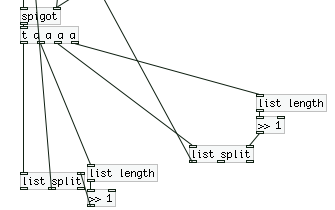
it's a recursive thing: I'll walk through part of an example:
say the list has 5 elements.
The list comes in, and goes into the open spigot.
so at this point the [t a a a a] is sending a list of 5 elements. the following is what happens to the right [list-split] at this moment:
the first 2 elements of the list are sent back to the upper trigger, and go back into the spigot, where they are split again into lists of length 1. element 1 goes back into the upper trigger and out of the outlet, and then the second does as well.
All of this happens before the list of 5 elements is even sent to the left [list split], because of the trigger. A similar thing occurs:
the last 3 elements of the 5-element list are sent to the upper trigger and into the open spigot, and then the first element of that is split off and sent out the outlet. Then the last 2 elements are sent through the spigot and split, and are sent out in order.
The crucial thing to understand is the recursive nature; it has to do with the depth-first message passing in pd.
The first half of the list is split off before the second half, and sent to be split in half again before the second half of the original list is even processed. So it goes the first half of the first half of the first half, etc. until the first element is sent to the outlet. Then it goes back up the "stack" to the second halves of the lists that it missed in doing the first half every time (this happens because of the triggers). So after the first element is sent, the second element is sent. After that, elements 3 and 4 (in a list since they weren't even processed to be split yet) are split and sent out in order. then elements 5-8, which are still in a list, are sent back and processed in the same manner.
Hopefully that's somewhat clear..
(rambling extra stuff:)
From a "computer science" perspective, you could say that you process the first half and put the second half on a "stack" , and then go into the first half, split it in half, put the second half on the "stack", etc. And then after the 1st element is put out, repeat that process for each thing on the top of the stack until you end up with 1 element:
in "pseudocode" (with a datatype "list" and an assumed stack):
function splitlist (list inlist) {
         list firsthalf;
         list secondhalf;
         if length(inlist) == 1 then {
                     output(inlist); -- pass the element
                     if stack exists then {
                            secondhalf = popstack(); -- get the next thing on the stack
                            splitlist(secondhalf); -- call the function recursively
                     }
        } else {
                   firsthalf, secondhalf = split(inlist); -- split the list, pass to variables
                   pushstack(second half); --- push the second half onto the stack
                   splitlist(firsthalf); -- call the function recursively
         }
}
I think that in reality most of this is taken care of in the computer's call stack, though not completely sure on how the memory for the lists is dealt with
 posted in technical issues
how does [list drip] actually work?
Hi folks,
This is going to be a weird and long post, because I am walking through my thinking as much as I am asking questions. Sorry for the length in advance.
I've recently become fascinated with the many possibilities afforded by the list-abs library, and what strikes me at is that [list-drip] seems to be at the heart of most of them. For those of you who don't know, [list-drip] works by separating (aka "dripping") an incoming list into its individual elements (atoms?). This allows you to do a bunch of operations on these elements before repacking them into a new list. For example, [list-compare] functions like [==] but for lists by checking each list's elements against each other to give out a binary yes or no answer. And of course, [list-drip] is at the core here.
I would like to really figure out the logic behind [list-drip], but the help file (well, really the abstraction itself) is deceptively simple. This is because [list-drip] itself is but an abstraction based on the clever use of [list-split] (which is not an abstraction but an external) and some strange binary math and triggering mechanisms that I don't understand.
Here's the [list-drip] extraction itself:
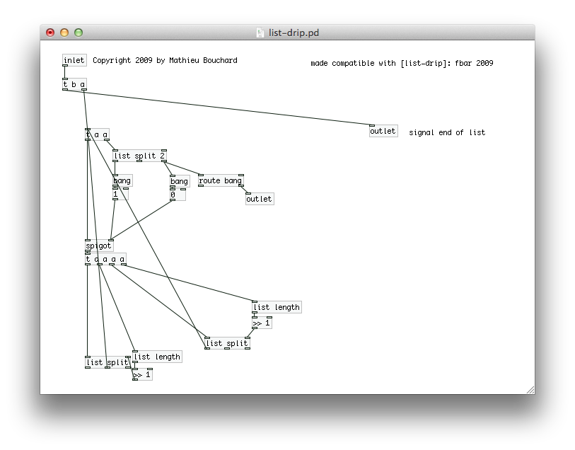
I'll just talk about this abstraction and ask questions along the way.
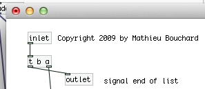
Here's the first part. Pretty simple. [trigger] is passing the entire list on, and then sending a bang. This seems weird but I've heard that pd will take care of all the operations starting at the right outlet of trigger first, so the bang is guaranteed to come after the list has been "dripped."
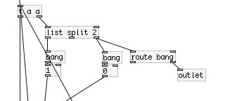
Here's the second part, where we have [list split] doing a binary "less than" operation on the list. "If the list is less than 2 elements long, it gets sent to the outlet and the [spigot] closes, else, open the spigot." This [trigger] then passes a copy of the list onto [spigot] which is either open or closed based on the above result.
Ok now here is where things start to get crazy. The list is now fed into two identical [list split] mechanisms with some weird math going on, which are also feeding back into the top of the second [trigger].
Let's break this down really quick:
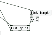
First, we get the length of the list, then we feed it into [>> 1]. With some research in pd and the on the web, I come to the conclusion that we are basically dividing (integer division) by 2. This is setting the point for where [list split] outputs a list with only a certain number (but always half) of elements (using the first outlet). As I said before, this result is being fed back into the second [trigger].
So I think basically what's happening is this:
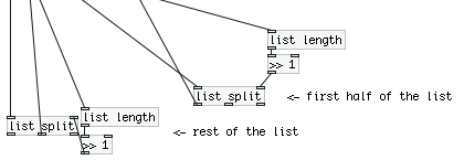
...where the rest of the list is either exactly half the total list length (if it's an even number) or half + 1 (if the total length is an odd number of elements).
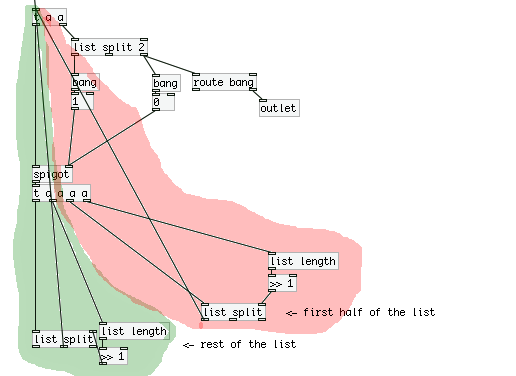
So we have two "loops" going on here, where on operates on the first half of the list (will call this the "red" loop, and the other operates on the second "green loop".
Now in terms of trigger ordering, what is happening here? Are we constantly triggering the red loop until there are no more operations, and then moving on the green loop? And what does this mean in the context of the patch? I'm confused about how [trigger] acts in these situations with many nested loops.
To troubleshoot, I attached a print the outlets of both the red and green **[list split]**s, and sent the list [a b c d 1 2 3 4( to [list drip]. Here's the output from the console:
first half: symbol a
second half: symbol b
first half: list a b
first half: symbol c
second half: symbol d
second half: list c d
first half: list a b c d
first half: 1
second half: 2
first half: 1 2
first half: 3
second half: 4
second half: 3 4
second half: 1 2 3 4
To me this output looks like it was printed backwards. Is there some weird interaction between [trigger] and [print] going on?
Furthermore, how is the output of [list drip] organized so that each element is output in it's sequential order? How does the green loop know to wait for the red loop to finish?
 posted in technical issues
Beatmaker Abstract
http://www.2shared.com/photo/mA24_LPF/820_am_July_26th_13_window_con.html
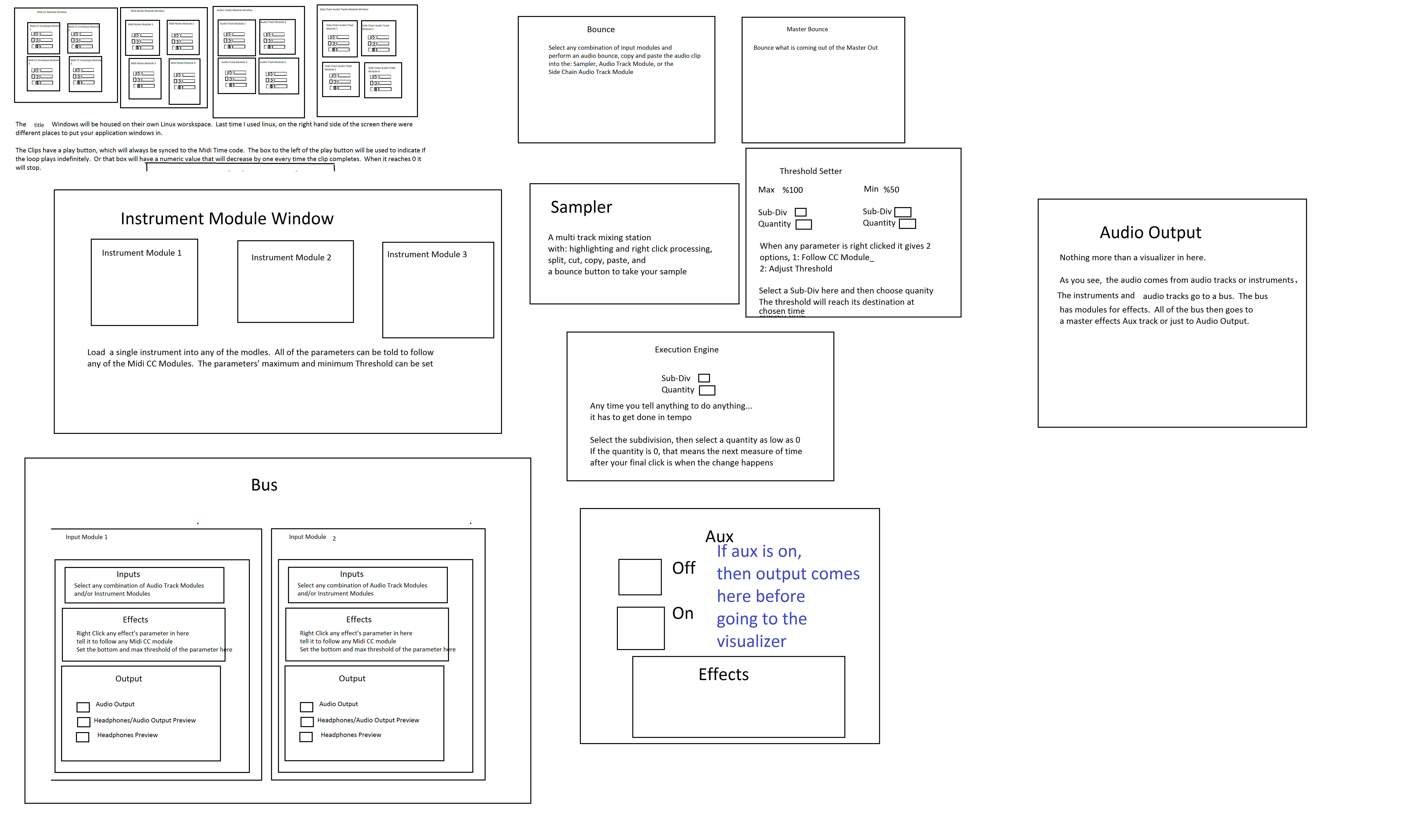
I conceptualized this the other day. The main reason I wanted to make this is because I'm a little tired of complicated ableton live. I wanted to just be able to right click parameters and tell them to follow midi tracks.
The big feature in this abstract is a "Midi CC Module Window" That contains an unlimited (or potentially very large)number of Midi CC Envelope Modules. In each Midi CC Envelope Module are Midi CC Envelope Clips. These clips hold a waveform that is plotted on a tempo divided graph. The waveform is played in a loop and synced to the tempo according to how long the loop is. Only one clip can be playing per module. If a parameter is right clicked, you can choose "Follow Midi CC Envelope Module 1" and the parameter will then be following the envelope that is looping in "Midi CC Envelope Module 1".
Midi note clips function in the same way. Every instrument will be able to select one Midi Notes Module. If you right clicked "Instrument Module 2" in the "Instrument Module Window" and selected "Midi input from Midi Notes Module 1", then the notes coming out of "Midi Notes Module 1" would be playing through the single virtual instrument you placed in "Instrument Module 2".
If you want the sound to come out of your speakers, then navigate to the "Bus" window. Select "Instrument Module 2" with a drop-down check off menu by right-clicking "Inputs". While still in the "Bus" window look at the "Output" window and check the box that says "Audio Output". Now the sound is coming through your speakers. Check off more Instrument Modules or Audio Track Modules to get more sound coming through the same bus.
Turn the "Aux" on to put all audio through effects.
Work in "Bounce" by selecting inputs like "Input Module 3" by right clicking and checking off Input Modules. Then press record and stop. Copy and paste your clip to an Audio Track Module, the "Sampler" or a Side Chain Audio Track Module.
Work in "Master Bounce" to produce audio clips by recording whatever is coming through the system for everyone to hear.
Chop and screw your audio in the sampler with highlight and right click processing effects. Glue your sample together and put it in an Audio Track Module or a Side Chain Audio Track Module.
Use the "Threshold Setter" to perform long linear modulation. Right click any parameter and select "Adjust to Threshold". The parameter will then adjust its minimum and maximum values over the length of time described in the "Threshold Setter".
The "Execution Engine" is used to make sure all changes happen in sync with the music.
IE>If you selected a subdivision of 2, and a length of 2, then it would take four quarter beats(starting from the next quarter beat) for the change to take place. So if you're somewhere in the a (1e+a) then you will have to wait for 2, 3, 4, 5, to pass and your change would happen on 6.
IE>If you selected a subdivision of 1 and a length of 3, you would have to wait 12 beats starting on the next quater beat.
IE>If you selected a subdivision of 8 and a length of 3, you would have to wait one and a half quarter beats starting on the next 8th note.
http://www.pdpatchrepo.info/hurleur/820_am,_July_26th_13_window_conception.png
 posted in abstract~