Issues with this save abstraction
Hello all.
I have been stuck for the past day or two with this save abstraction and slowly have been piecing it together. I almost have the end result I want. But for some reason only the first line is being updated for example If any information is updated by the abstraction those changes will be saved to the first line and not its own designated line.
Also I should be seeing a file path as the last argument in the text doc but "symbol" and "float" shows up for every line except for the first few lines.
Here is the save abstraction. OBBuildSongSavePatternPath.pd
Below are the results of the save abstraction.
0 0 0 0 C:/Users/Retro/Documents/Samples/TCustomz Productionz Drum Sample Pack Vol. II_hsud0hsldkf/TCustomz Productionz Drum Sample Pack Vol. II/hi hats/hat 06.wav
;
0 0 0 0 C:/Users/Retro/Documents/Samples/TCustomz Productionz Drum
Sample Pack Vol. II_hsud0hsldkf/TCustomz Productionz Drum Sample Pack
Vol. II/kicks/kick 02.wav;
0 0 0 0 symbol;
0 0 0 0 symbol;
0 0 0 0 symbol;
0 0 0 0 symbol;
0 0 0 0 symbol;
0 0 0 0 symbol;
0 0 0 0 symbol;
0 0 0 0 symbol;
0 0 0 0 symbol;
0 0 0 0 symbol;
0 0 0 0 symbol;
0 0 0 0 symbol;
0 0 0 0 symbol;
0 0 0 0 symbol;
0 0 0 0 symbol;
0 0 0 0 float;
0 0 0 0 float;
0 0 0 0 float;
0 0 0 0 float;
0 0 0 0 float;
0 0 0 0 float;
0 0 0 0 float;
0 0 0 0 float;
0 0 0 0 float;
0 0 0 0 float;
0 0 0 0 float;
0 0 0 0 float;
0 0 0 0 float;
0 0 0 0 float;
0 0 0 0 float;
0 0 0 0 float;
0 0 0 0 float;
0 0 0 0 float;
0 0 0 0 float;
0 0 0 0 float;
0 0 0 0 float;
0 0 0 0 float;
0 0 0 0 float;
0 0 0 0 float;
0 0 0 0 float;
0 0 0 0 float;
0 0 0 0 float;
0 0 0 0 float;
0 0 0 0 float;
0 0 0 0 float;
0 0 0 0 float;
0 0 0 0 float;
0 0 0 0 float;
0 0 0 0 float;
0 0 0 0 float;
0 0 0 0 float;
0 0 0 0 float;
0 0 0 0 float;
0 0 0 0 float;
0 0 0 0 float;
0 0 0 0 float;
0 0 0 0 float;
0 0 0 0 float;
0 0 0 0 float;
0 0 0 0 float;
0 0 0 0 float;
0 0 0 0 float;
0 0 0 0 symbol;
 posted in technical issues
Pduino, what firmata for both in and outs
@cfry https://forum.pdpatchrepo.info/topic/12118/pduino-simultaneous-analog-input-and-digital-output-problems
I have just found the Floss manual version in English.
For me it is a bit harder to read but....... http://write.flossmanuals.net/pure-data/starting-pduino/
has a more detailed instructible.
......and both require https://at.or.at/hans/pd/objects.html#pduino
[arduino-test] allows you to set all the pins as desired.
David.
 posted in I/O hardware diy
PDuino - simultaneous analog input and digital output problems
Hello!
I'm trying to get PDuino working in a setup where I have Arduino reading an analog input and also controlling a relay on the digital output. I have tried the StandardFirmata sketch for Arduino but it doesn't seem to be able to read the analog input with this sketch (it controls the digital output no problem with this however). When I use the AllInputsFirmata instead, it reads the analog inputs just fine but I'm getting no response on the digital outputs.
Is there perhaps something where you can't use analog inputs and digital outputs at the same time? Could I be doing something else wrong? I've tried all the other Firmata sketches that come with the Pduino setup files (out of desperation!) but with no success. Any help greatly appreciated!
 posted in technical issues
Bug in Pd Patch
@ketchupee1 Ok... found...... you put me on the path @bocanegra although maybe only because you had understood it already.
Wood for trees and all that.
Not a bug.
Always feel silly when the logic jumps off the page.
The patching fault is at [trigger]
The float is not sent to the right inlet of the [sel] because the chain reaches around and back to the trigger when there is a match...... in a loop until there is a change of float value...... and then the float that triggered the loop is sent to the right inlet of [sel] after that operation has completed (too late now).
A [pipe] after [random] breaks that chain, as does a [delay] before [random].
[pipe] insists that floats pass through in order that they arrive, holding up the loop until the first float has completed all of its operations, and [delay] holds up the chain for long enough for the second operation of [trigger] to complete first.
The loop itself is not a problem. It is that it interupts the operation of the trigger.
[golf1] works because there is no [trigger] ordering before [sel], and that was the clue....
The first float is not compared.
The following floats are.
But if a bang is sent from the left outlet of [sel] the resulting float from [random] is compared with the first of the matching floats which is now the argument of [sel] from the last float banged into its right inlet when there was no match and the [sel] operation had completed. A subsequent identical pass will of course be the same as the first and so it works fine.
Needed some time bored on a train.
Of course [delay] in this case is a bug, but we are happy to call it a feature. We perceive time as something that cannot be stopped because something that should have happened has not.
"Time waits for no man".
But the left outlet of trigger really should not fire until the right outlet has run it's course.
[delay] cheats..... saying "Yeah, OK, but........ I'll do it later.... honest", and throws the completion into the next schedule.
Just as well.
David.
posted in patch~
Audio Settings for multichannel with MOTU 828 mk3
Hi Matthieu,
I see your post is a little bit old but I'm experiencing the exact same problem now with my setup.
I'm using a Windows 7 machine with a MOTU 828x sound card connected via USB to the PC and Pd 0.48.1 vanilla.
Here what I've done:
- I've checked the "Use Stereo Pairs for Windows Audio" inside the "MOTU Audio Console";

- opened PD and selected "standard MMIO" as driver from the "Media" menù;
- now here's the list of outputs as it appears from the drop-down menu of "Media/Audio Setting.../Output device":
- MOTU Analog 3-4
- Loudspeakers (devide High ...
- MOTU Main-Out 1-2
- MOTU ADAT optical A 3-4
- Digital Output MOTU Audio
- MOTU ADAT optical A 1-2
- MOTU Analog 1-2
- MOTU ADAT optical A 7-8
- MOTU ADAT optical B 3-4
- MOTU Analog 7-8
- MOTU Analog 5-6
- Digital Output
- MOTU SPDIF 1-2
- MOTU ADAT optical B 1-2
- MOTU ADAT optical A 5-6
- MOTU Phones 1-2
As you see this list is pretty messed up and the names of logical consecutive output channels are not consequential. I would like to have 8 analog outputs from my MOTU so I selected the first item on the list (MOTU analog 3-4) then specified a total of 22 channels.
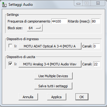
I'm obliged to set 22 as the total number of output channels because in my list MOTU Analog 5-6 are the last analog elements present. Because items in the list represent pairs of channels, this item corresponds to logical channel 21 and 22.
- Then I created the dac object this way:
[dac~ 13 14 1 2 21 22 19 20]
Here's an image
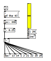
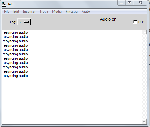
This way I'm able to hear sound on all analog outputs of the MOTU even if I'm experiencing variuous 'clicks' and a series of "resyncing audio" messages inside the PD console...
I confess, this method is the only way I'm able to make this setup work but it seems to me to be pretty messy and not intuitive at all.
What seems to be even worse is that analog audio outputs inside the device list seems to change their order at each computer restart, so every time I have to restart from scratch.
- Is there some easier solution to this problem?
- Maybe a preference file I can create for PD to load at each startup containing all these settings?
- or there may be a way to programmatically select correct "analog outputs" from the device list in my patch (even if string parsing doesn't seem to be so easy in PD to me).
- Would launching PD from console, maybe from an ad-hoc script, solve the problem?
Thank you so much for your support
M
 posted in technical issues
Purr Data GSoC 2018
Hello,
Guess what-- Purr Data was accepted as a mentoring organization
for Google Summer of Code 2018! This is a program where we mentor students
who code up new features and improvements to Purr Data, in a program that
runs roughly from May to August.
I'd like to invite people here to become mentors.
Now, I know most people will instantly think they couldn't possibly have
the knowledge necessary to become a mentor.
So I added an idea to the bottom of the list of projects with that in mind:
https://git.purrdata.net/jwilkes/summer-of-code-ideas-list/blob/master/README.md
If you notice, it is possible to complete that project
using only Pd as the programming language. In other words, if you know you're
way around Pd well enough to suggest how to structure and create
such a library, then you possess enough knowledge to be a Purr Data mentor
for GSoC.
Additionally, I would invite people to suggest similar types of project ideas
that only require the Pd language in order to complete. And if that project is
within your area of expertise, consider becoming a GSoC mentor for Purr Data.
Finally, if you are interested in participating as a student consider applying
for GSoC-- the application process for students begins March 12.
Feel free to reply here or on the l2ork dev list:
http://disis.music.vt.edu/cgi-bin/mailman/listinfo/l2ork-dev
Best,
Jonathan
 posted in news
Lissa Executable / ofxOfelia compile error (Solved)
@cuinjune I tried to compile the lissa seq patch. but when i open the executable it opens only a small empty window.
i also tried to compile a help patch for testing, with the same result.
but your example works fine(Win32Example).
 posted in libpd / webpd
Build a MIDI controller with the Arduino, Firmata and Pure Data
Time to start contributing some knowledge back to the wonderful world that is the internet; today, a step by step nice and easy tutorial on getting started to building your own MIDI controllers with the arduino.
When researching for my ableton controller project, I didn’t find much out there about using firmata on an arduino to send data to software. The standard approach just seemed to be create the code in the arduino language, upload it to your board and hack one of those MIDI to USB cables as a bodge job way of getting the MIDI out of the arduino.
So why firmata and pure data? Well the whole idea of firmata is that you flash it to your arduino, and it throws out serial about whats going on with the arduino inputs and outputs, then you decide how the software treats the readings coming in and going out.
Theory out the way, lets build some controllers. You’ll need a few things…
HARDWARE:
An arduino and something to wire into it (for this i’ll be using a pot)
A USB cable for your arduino
SOFTWARE:
Arduino – http://arduino.cc/en/Main/Software
Pure Data – http://puredata.info/downloads
Firmata – http://at.or.at/hans/pd/objects.html#pduino
Something to patch your new controller into; like Reason or Ableton Live
- SETTING UP FIRMATA AND PURE DATA
Install Pure Data and create a folder to store all your patches somewhere. Unzip Firmata and add the files ‘arduino.pd’, ‘arduino-test.pd’ and ‘arduino-help.pd’ to your new Pure Data folder. The ‘arduino.pd’ file is the object that we use in PD for opening up communication with your arduino and routing it to PD. Done? Awesome, your software is almost set up.
- FLASHING FIRMATA TO YOUR ARDUINO
Install the latest version of arduino and open it up. Connect your arduino with the USB cable to your laptop (i’m using a macbook for this by the way). In the example patches, open up “Standard Firmata”, select your board (im using an arduino mega), and your serial port (look for tty.usbserial for use with a USB cable). Then compile and hit the upload button and your arduino is now ready to use firmata and communicate with Pure Data!
- WIRING UP A POT
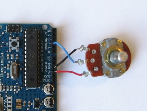
Potentiometers are cool, and theres a great arduino tutorial of how to wire one up here: http://www.arduino.cc/en/Tutorial/Potentiometer
Basically, all you need to know is that there are three pins; your two outer pins govern voltage flow across the pot, meaning one has to be 5V and the other has to be ground. It doesn’t matter which, but your 5v pin is going to be where your pot reads maximum, so convention dictates this should be the right hand pin. The center pin needs to be connected to an analog in on the arduino and will read the value of the pot as it sweeps from ground (0v) to 5v.
All wired up? Plug it into your laptop and open Pure Data, we’re ready to get things talking.
- SETTING UP OUR PATCH
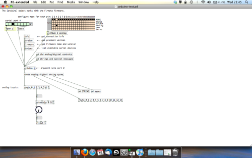
Open the example “arduino-test.pd” Pure Data patch you copied over earlier. It should look like this one…
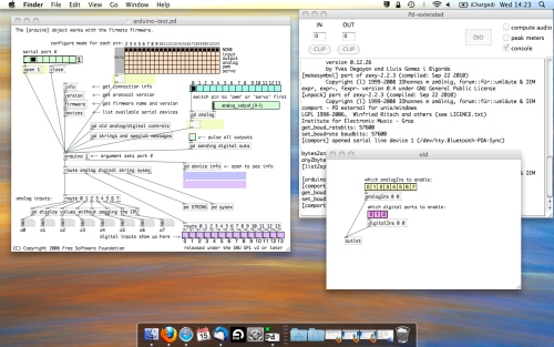
The test patch has everything we need to open a connection and enable pins. Firstly, lets delete a bunch of stuff and make our window a bit bigger. Hit Command + E to enter edit mode in Pure Data.
Ok a quick explaination; the key component here is the ‘arduino’ object. This is being drawn from the file you copied in earlier, and is what communicated with your arduino. Here we can do everything to control the arduino from opening a connection, to receiving data.
The large grid allows us to set the mode of each pin on the arduino. Remember pins 0 and 1 are reserved for Rx and Tx. I’m using analog pin 4 for this demo, so I’ve set my pin mode for pin 4 to ‘analog’.
Now we can plug our arduino in and get a reading from the potentiometer.
- ARDUINO INTO PURE DATA
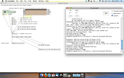
With your arduino plugged in, hit command and E to bring us out of edit mode. In our patch, click on ‘Devices’ above the arduino object and open up the pure data terminal. (That other thing that loads with PD that has all the scary code in)
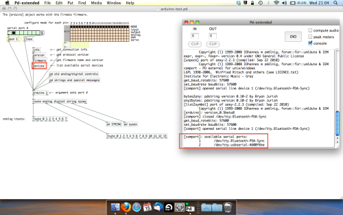
The “Devices” message connected to the arduino object pings your computer to find what devices are connected and on what serial ports. Since we’re using a USB cable to connect our arduino, we’re looking for something with ‘usbserial’ in it, in this case; port 2.
Select the relevent port in the green box at the top (remember the first box is ‘0’, second is ‘1’ and so forth) and hit ‘Open’ to establish a connection. Check the terminal to see if the connection was sucessful.

Now lets check we’re getting something in. Create a number box (Command + 3) and connect it to the relevent pin on the ‘Route analog’ box at the bottom. In this case, pin 4.
One more thing; if you’re not getting any readings in, you’ll need to click on ‘pd old analog/digital controls’ and enable your pins here too. What I tend to do in my patches is just not include the large grid but make my own ‘old pd’ controls custom to what i’m enabling/disabling to save space.
Here’s what the ‘old analog/digital controls’ subpatch looks like (pin 4 enabled)…
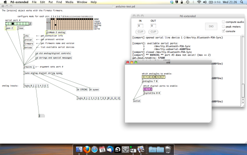
Come out of edit mode and check that you’ve got readings. If so congratulations! If not, troubleshoot, start with making sure your usb connection is opened, make sure all the correct pins are enabled (remember you’re counting from 0 not 1 on most of these buttons in PD, it’s just the way computers work).
- SCALING READINGS TO MIDI
So we’ve got a reading and chances are it’s to 3 decimal places between 0 to 1. No problem, create a new object (Command + 1) and type “autoscale 0 127”. This allows us to scale the input to a min and max value, in this case 0 to 127 of MIDI. Next, lets get things looking nice, create a new object and type “knob”. Connect this AFTER the autoscale object. (the knob is default set to read inputs from 0 to 127. Then create another number to display the scaled MIDI data coming out, and finally a new object and type “ctlout 1”.
It should look something like this…
The second box should be outputing values from 0 – 127 now, and the knob giving a visual representation of your potentiometer.
Now lets patch it into ableton…
- PURE DATA TO ABLETON LIVE
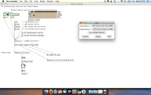
Firstly, you’ll need to set up your macs IAC driver if you’ve not done this. Basically you’ll need to go into Audio/MIDI preferences and enable your IAC driver. Then create a new input and output. One for input to DAW and one for output from DAW. Google around for a tutorial on this, its really simple, a 30 second job.
After you’ve set up your IAC driver, go back to PD and go to preferences > MIDI Settings, and connect your IAC driver.
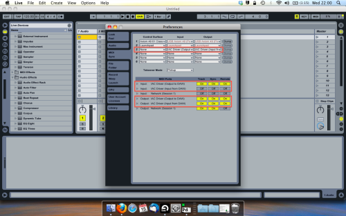
Open ableton and go to its MIDI preferences. Create a device listing for your IAC driver and enable its ins and outs into ableton like so…
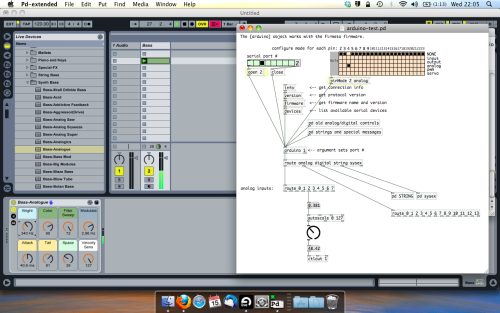
And thats it! Create an instrument and try to assign something! I’ve got it controlling the brightness of a bass sound here.
Shout out for Facu who requested this tutorial. Hopefully it’ll help some of you looking to get into this stuff and start building things but with no idea where to start.
 posted in tutorials
audio error when external monitor is plugged in
Hi again, and thanks for your suggestions.
I tried lowering the gemwin fps from 60 to 20, which I believe is the default for gemwin, but that didn't help. I still got an audio error with crackling.
I also tried slowing down the flashes. Also, no luck.
What I did find out is that the error only occurs when the gem window is positioned on the other monitor; having been dragged with the mouse before I've set the patch in motion. This error also occurs if I drag the gemwin around while my patch is functioning with the metro without any monitor connected. In other words, it's clear that simply having the external monitor connected and functional is not the cause for the error. It seems to be an issue with coordinating the video signal with another monitor, or when the gemwin is being interfered with while the patch is in progress irrespective of the connection of an external monitor. This may not seem like a revelation, but at least I know it's not simply the presence of the second monitor attached to my computer that's causing the audio error. I'll keep trying things. Thanks for offering to run the patch on your own system. I'll upload it, but I don't know how useful it will be as you won't have all the audio that's probably encumbering the system. For that I'd also have to upload the sound files - about 8 cello samples. Anyway, here's the patch, and thanks for your help .Study no 3 draft4.pd
 posted in technical issues
[sploat] / [gloat] - split float & glue float
splits and joins the sign, exponent, and mantissa of a float
[sploat]
accepts bangs and floats
accepts 1 creation argument for assigning the stored value
has 1 extra inlet for assigning the stored value
outputs the sign, exponent, and mantissa of the stored float
[gloat]
accepts bangs and floats (mantissa is assigned the float)
accepts 3 creation arguments for assigning the mantissa, exponent, and sign
has 3 extra inlets for assigning these values
outputs a float by combining these values together
help file included
 posted in extra~