Having lots of switches into Pd
@alexandros said:
Have you detected whether the crash happens with
else if (in == 'd')orelse if (in == 'p')?
It happens only in else if (in == 'p'). When I bypass that I can update snapshot~ by 1 ms (I assume that 'c' will still be sent by 1 ms intervals).
In the Pd patch it's probably better to swap the $1 and $2 values in the messages. Have the channel set in a cold inlet and the value in a hot one and then write this message
print $2c$1v
Ok I did that.
I see in the screenshot of the patch that the PWM message is not connected to [comport]. Is this for some particular reason?
It is to make sure Pd does not crash/freeze until I want to try the code.
Maybe the 10ms interval for sending a PWM value to [comport] is a bit too fast. Did you try something slower, like 50ms?
That made it work. If I use six pwm pins the limit is 150 ms before crash.
Question 1: Could there something bad that happens around else if (in == 'p')? In another code snippet you used this format:
  while(Serial.available()){
    byte inByte = Serial.read();
    if((inByte >= '0') && (inByte <= '9'))
    temporary = 10 * temporary + inByte - '0';
    else{
      if(inByte == 'p'){
        pwmLEDvalue = temporary;
        temporary = 0;
      }
      else if(inByte == 'd'){
        dspLEDstate = temporary;
        temporary = 0;
      }
    }
    analogWrite(pwmLED, pwmLEDvalue);
    digitalWrite(dspLED, dspLEDstate);
  }
compared to this in the current sketch:
if (Serial.available()) {

    static int temp;
    byte in = Serial.read();

    if (isDigit(in)) temp = temp * 10 + in - '0';

    else if (in == 'c') {
      channel = temp;
      temp = 0;
    }

    else if (in == 'd') {
      digitalWrite(outPins[channel], temp);
      temp = 0;
    }

    else if (in == 'p') {
      analogWrite(pwmPins[channel], temp);
      temp = 0;
    }

  }
Question 2: Is this crash of Pd and the computer (macOS Mojave) expected behavior in a situation like this? If it is not, maybe it should be reported as a bug. It happens consistently.
Thoughts: Could there be a problem in [comport]? This crash behavior is identical with the problems I had when using Pdunio/Firmata.
 posted in I/O hardware diy
Having lots of switches into Pd
@alexandros said:
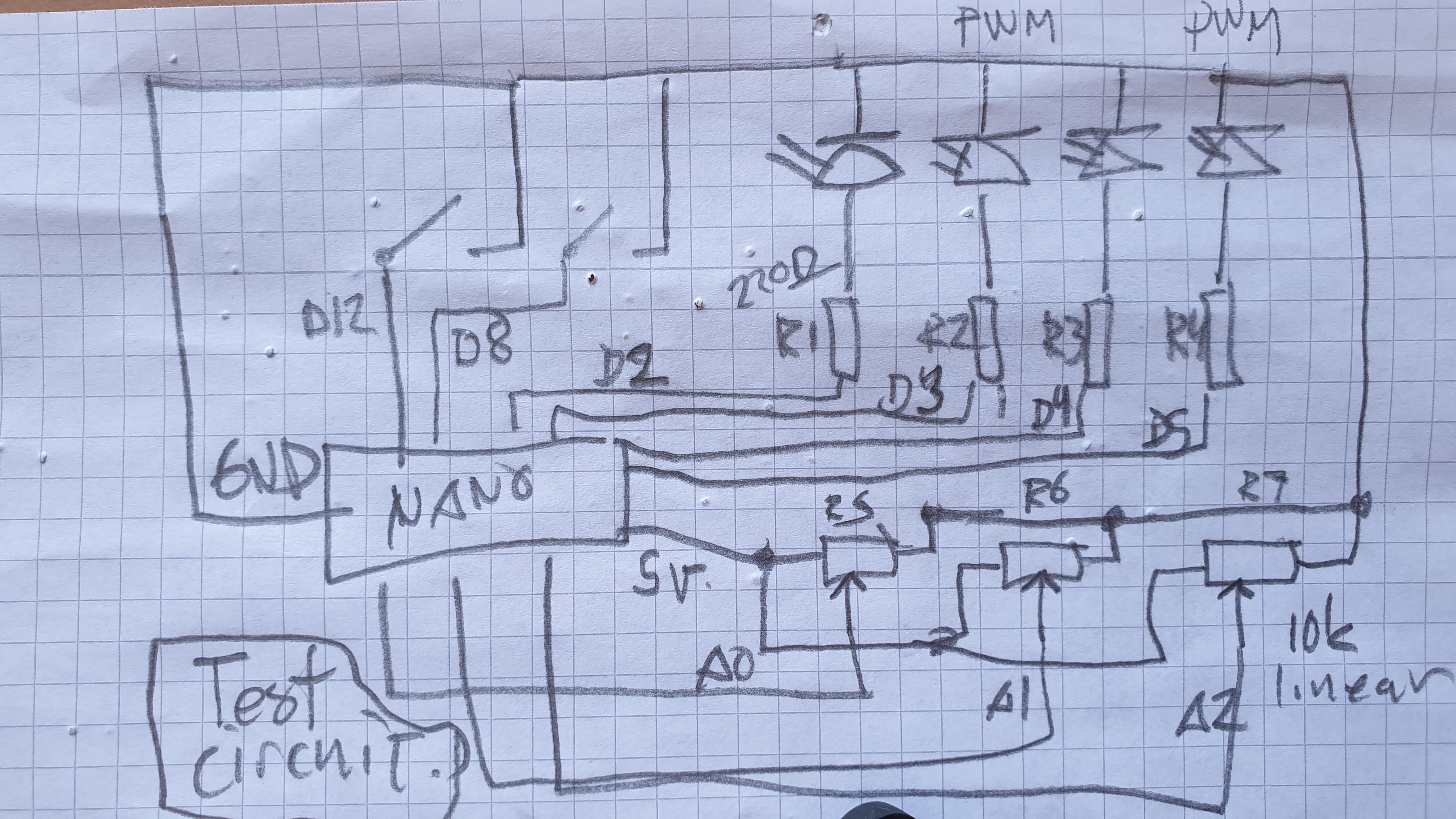
@cfry the thing is that the last bit of code you posted seems just fine, excluding the calling to pinMode where you're enabling the integrated pull-up resistors. Can you try that code removing these lines in setup(), and instead of heat sensitive sensors or whatever you're currently using, use simple potentiometers and verify whether that works or not? In case it doesn't work, please post a diagram of your circuit in some way (even hand-drawn is ok), as well as the full Arduino sketch and a screenshot of the Pd patch.
int outPins[3] = {2, 4, 7};
int pwmPins[6] = {3, 5, 6, 9, 10, 11};

int channel = 0;

int inPins[2] = {8, 12};
int analogPins[8] = {0, 1, 2, 3, 4, 5, 6, 7};

// int debug_skip = 0;

void setup() {

   for (int i = 0; i < 3; i++) {
    pinMode(outPins[i], OUTPUT);
  }
    for (int i = 0; i < 6; i++) {
    pinMode(pwmPins[i], OUTPUT);
  }
    for(int i = 0; i < 2; i++) {
    pinMode(inPins[i], INPUT_PULLUP);
  }

  Serial.begin(115200);

}

void loop() {

//DO OUTPUTS

  if (Serial.available()) {

    static int temp;
    byte in = Serial.read();

    if (isDigit(in)) temp = temp * 10 + in - '0';

    //quote out this section to avoid crash

    else if (in == 'c') {
      channel = temp;
      temp = 0;
    }

    else if (in == 'd') {
      digitalWrite(outPins[channel], temp);
      temp = 0;
    }

    else if (in == 'p') {
      analogWrite(pwmPins[channel], temp);
      temp = 0;
    }

    //end quote out here

  }

// DO INPUTS

Serial.print("analog");

  for(int i = 0; i < 8; i++){

    unsigned int analogVal = analogRead (analogPins[i]);

    Serial.print(" ");
    Serial.print(analogVal);
  }

  Serial.println();

  Serial.print("digital");

  for(int i = 0; i < 2; i++) {

    unsigned int digitalVal = digitalRead(inPins[i]);

    Serial.print(" ");
    Serial.print(digitalVal);
  }

  Serial.println();

}
If I do the following PureData will always freeze and requires force quit. Occasionally the whole OS becomes sluggish/freeze and need a reboot.
- Have this code snippet in the Arduino sketch
    //quote out this section to avoid crash

    else if (in == 'c') {
      channel = temp;
      temp = 0;
    }

    else if (in == 'd') {
      digitalWrite(outPins[channel], temp);
      temp = 0;
    }

    else if (in == 'p') {
      analogWrite(pwmPins[channel], temp);
      temp = 0;
    }

    //end quote out here
- Connect [print $1c$2p] -> [comport]
(I have also noted different behavior using [comport] from the tutorial by copy and paste compared to creating a comport object (cmd+1 and then typing). At times the latter did not work at all, but after reboot of the system both seems to work.)
Thanks for helping
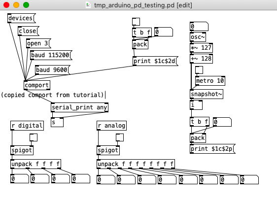
Here is the patch from screenshot above:
tmp_arduino_pd_testing.pd
posted in I/O hardware diy
Having lots of switches into Pd
@alexandros now pwm and digital output work fine, but when I try to merge with digital and analog inputs it goes wrong. the leds flicker randomly. If you remove the code below
// do input pins: flicker stops. :/
int outPins[3] = {2, 4, 7};

int pwmPins[6] = {3, 5, 6, 9, 10, 11};

// a global variable to hold which LED we want to control (either digital or PWM)
int channel = 0;

int inPins[2] = {12, 13};

int analogPins[8] = {0, 1, 2, 3, 4, 5, 6, 7};

void setup() {

   for (int i = 0; i < 3; i++) {
    pinMode(outPins[i], OUTPUT);
  }
    for (int i = 0; i < 6; i++) {
    pinMode(pwmPins[i], OUTPUT);
  }
    for(int i = 0; i < 2; i++) {
    pinMode(inPins[i], INPUT);
  }

  pinMode(A0, INPUT_PULLUP);
  pinMode(A1, INPUT_PULLUP);
  pinMode(A2, INPUT_PULLUP);
  pinMode(A3, INPUT_PULLUP);
  pinMode(A4, INPUT_PULLUP);
  pinMode(A5, INPUT_PULLUP);
  pinMode(A6, INPUT);
  pinMode(A7, INPUT);

//DEFAULT works with thermistors,
//INTERNAL with transitor thermostats
  analogReference(DEFAULT);

  Serial.begin(115200);

}

void loop() {

  //do output pins:

  if (Serial.available()) {
    static int temp;
    byte in = Serial.read();
    if (isDigit(in)) temp = temp * 10 + in - '0';
    else if (in == 'c') {
      channel = temp;
      temp = 0;
    }
    else if (in == 'd') {
      digitalWrite(outPins[channel], temp);
      temp = 0;
    }
    else if (in == 'p') {
      analogWrite(pwmPins[channel], temp);
      temp = 0;
    }
  }

  // do input pins:

Serial.print("analog"); // use "knobs" as a keyword so you can receive
  // the knob values as a list with a [r analog] in Pd
  for(int i = 0; i < 8; i++){
    unsigned int analogVal = analogRead (analogPins[i]);
    Serial.print(" "); // first print a white space to separate the "knob" keyword from the values
    // and the values from each other
    Serial.print(analogVal); // then  print the actual knob value
  }
  Serial.println(); // finally print a newline character to denote end of data for keyword "knobs"

  Serial.print("digital");
  for(int i = 0; i < 2; i++) {
    unsigned int digitalVal = digitalRead(inPins[i]);
    Serial.print(" ");
    Serial.print(digitalVal);
  }
  Serial.println();
}
Having lots of switches into Pd
First of all, don't separate functions for reading the serial data, even if you want to read data for different kinds of stuff.
Combining digital with PWM pins should be sort of straight forward. Here's some example code:
int digitalPins[4] = {2, 4, 7, 10};
// use an array for all the pins of similar type, e.g. PWM pins, like below
int pwmPins[6] = {3, 5, 6, 9, 11, 12}; // can't remember the exact pin numbers with PWM, change accordingly

// a global variable to hold which LED we want to control (either digital or PWM)
int channel = 0;

void setup() {
  for (int i = 0; i < 4; i++) {
    pinMode(digitalPins[i], OUTPUT);
    pinMode(pwmPins[i], OUTPUT);
  Serial.begin(115200);
}

void loop() {
  if (Serial.available()) {
    static int temp;
    byte in = Serial.read();
    if (isDigit(in)) temp = temp * 10 + in - '0';
    else if (in == 'c') {
      channel = temp;
      temp = 0;
    }
    else if (in == 'd') {
      digitalWrite(digitalPins[channel], temp);
      temp = 0;
    }
    else if (in == 'a') {
      analogWrite(pwmPins[channel], temp);
      temp = 0;
    }
}
Check this code with Pd by sending messages of the type print $1c$2d for digital values and print $1c$2a for analog values. $1 is the led number (incrementing, starting from 0), and $2 is the value you want to write, 0-1 for digital and 0-255 for PWM.
 posted in I/O hardware diy
Having lots of switches into Pd
@alexandros
This code sort of works with wip_multiple_PWM.pd
// merging works but pwm leds are choppy.

// number of elements in arrays need to
// match for() cycles in void setup and void loop
int pinsIn[2] = {2, 4};
int pinsAnalog[8] = {0, 1, 2, 3, 4, 5, 6, 7};

int pin = 0;
int val = 0;
int pinsOut[2] = {7, 12};

//TMP setup pwm:

// variables to hold pin numbers
int pwmLED1 = 3;
int pwmLED2 = 5;
int pwmLED3 = 6;
int pwmLED4 = 9;
int pwmLED5 = 10;
int pwmLED6 = 11;

// variables to hold pin states
int pwmLEDvalue1;
int pwmLEDvalue2;
int pwmLEDvalue3;
int pwmLEDvalue4;
int pwmLEDvalue5;
int pwmLEDvalue6;

//should this be omitted and use the a
// variable to hold and assemble incoming data
int temporary;

//END TMP pwm setup

void setup()
{
  //set up a total of pins for digital input (has to match number of elements in array)
  for(int i = 0; i < 2; i++)
  pinMode(pinsIn[i], INPUT);

  for (int i = 0; i < 2; i++) {
    pinMode(pinsOut[i], OUTPUT);
    digitalWrite(pinsOut[i], LOW);
  }

//DEFAULT works with thermistors,
//INTERNAL with transitor thermostats

  analogReference(DEFAULT);

  pinMode(A0, INPUT_PULLUP);
  pinMode(A1, INPUT_PULLUP);
  pinMode(A2, INPUT_PULLUP);
  pinMode(A3, INPUT_PULLUP);
  pinMode(A4, INPUT_PULLUP);
  pinMode(A5, INPUT_PULLUP);
  pinMode(A6, INPUT);
  pinMode(A7, INPUT);

//TMP test pwm setup:

  pinMode(pwmLED1, OUTPUT);
  pinMode(pwmLED2, OUTPUT);
  pinMode(pwmLED3, OUTPUT);
  pinMode(pwmLED4, OUTPUT);
  pinMode(pwmLED5, OUTPUT);
  pinMode(pwmLED6, OUTPUT);

  Serial.begin(115200); // perhaps use a faster baud rate
}

void loop()
{
  Serial.print("knobs"); // use "knobs" as a keyword so you can receive
  // the knob values as a list with a [r knobs] in Pd
  for(int i = 0; i < 8; i++){
    unsigned int knob = analogRead (pinsAnalog[i]);
    Serial.print(" "); // first print a white space to separate the "knob" keyword from the values
    // and the values from each other
    Serial.print(knob); // then  print the actual knob value
  }
  Serial.println(); // finally print a newline character to denote end of data for keyword "knobs"

  // the same technique applies to the switches too
  // receive the switch values as a list with [r switches]
  Serial.print("switches");
  for(int i = 0; i < 2; i++) {
    int switchVal = digitalRead(pinsIn[i]);
    Serial.print(" ");
    Serial.print(switchVal);
  }
  Serial.println();

  //handle digital outputs
  if (Serial.available()) {
    static int temp;
    byte in = Serial.read();
    if (isDigit(in)) {
      temp = temp * 10 + in - '0';
    }
    else if (in == 'p') {
      pin = temp;
      temp = 0;
    }
    else if (in == 'v')  {
      val = temp;
      temp = 0;
      digitalWrite(pinsOut[pin], val);
    }
}

//TMP merge test PWMs:
while(Serial.available()){
     byte inByte = Serial.read();
     if((inByte >= '0') && (inByte <= '9'))
       temporary = 10 * temporary + inByte - '0';
     else{
       if(inByte == 'p'){
         pwmLEDvalue1 = temporary;
         temporary = 0;
       }
       else if(inByte == 'q'){
         pwmLEDvalue2 = temporary;
         temporary = 0;
       }
       else if(inByte == 'r'){
         pwmLEDvalue3 = temporary;
         temporary = 0;
       }
       else if(inByte == 's'){
         pwmLEDvalue4 = temporary;
         temporary = 0;
       }
       else if(inByte == 't'){
         pwmLEDvalue5 = temporary;
         temporary = 0;
       }
       else if(inByte == 'u'){
         pwmLEDvalue6 = temporary;
         temporary = 0;
       }
     }
     analogWrite(pwmLED1, pwmLEDvalue1);
     analogWrite(pwmLED2, pwmLEDvalue2);
     analogWrite(pwmLED3, pwmLEDvalue3);
     analogWrite(pwmLED4, pwmLEDvalue4);
     analogWrite(pwmLED5, pwmLEDvalue5);
     analogWrite(pwmLED6, pwmLEDvalue6);
     //digitalWrite(dspLED, dspLEDstate);
   }
}
This is the code without PWM control. It works fine.
//number of elements in arrays need to match for() cycles in void setup
int pinsIn[4] = {6, 7, 8, 9};
int pinsAnalog[8] = {0, 1, 2, 3, 4, 5, 6, 7};

int pin = 0;
int val = 0;
int pinsOut[4] = {2, 3, 4, 5};

void setup()
{
  //set up a total of pins for digital input (has to match number of elements in array)
  for(int i = 0; i < 4; i++)
  pinMode(pinsIn[i], INPUT);

  for (int i = 0; i < 4; i++) {
    pinMode(pinsOut[i], OUTPUT);
    digitalWrite(pinsOut[i], LOW);
  }
//DEFAULT works with thermistors,
//INTERNAL with transitor thermostats
// ELLER var det tvartom???
  analogReference(DEFAULT);

  pinMode(A0, INPUT_PULLUP);
  pinMode(A1, INPUT_PULLUP);
  pinMode(A2, INPUT_PULLUP);
  pinMode(A3, INPUT_PULLUP);
  pinMode(A4, INPUT_PULLUP);
  pinMode(A5, INPUT_PULLUP);
  pinMode(A6, INPUT);
  pinMode(A7, INPUT);

  Serial.begin(115200); // perhaps use a faster baud rate
}

void loop()
{
  Serial.print("knobs"); // use "knobs" as a keyword so you can receive
  // the knob values as a list with a [r knobs] in Pd
  for(int i = 0; i < 8; i++){
    unsigned int knob = analogRead (pinsAnalog[i]);
    Serial.print(" "); // first print a white space to separate the "knob" keyword from the values
    // and the values from each other
    Serial.print(knob); // then  print the actual knob value
  }
  Serial.println(); // finally print a newline character to denote end of data for keyword "knobs"

  // the same technique applies to the switches too
  // receive the switch values as a list with [r switches]
  Serial.print("switches");
  for(int i = 0; i < 4; i++) {
    int switchVal = digitalRead(pinsIn[i]);
    Serial.print(" ");
    Serial.print(switchVal);
  }
  Serial.println();

  //handle digital outputs
  if (Serial.available()) {
    static int temp;
    byte in = Serial.read();
    if (isDigit(in)) {
      temp = temp * 10 + in - '0';
    }
    else if (in == 'p') {
      pin = temp;
      temp = 0;
    }
    else if (in == 'v')  {
      val = temp;
      temp = 0;
      digitalWrite(pinsOut[pin], val);
    }
}
}
and here is the code from tutorial5 from Arduino for Pd'ers. It goes with arduinoforpdrs_tut5.pd
// variables to hold pin numbers
int pwmLED = 9;
int dspLED = 2;
// variables to hold pin states
int pwmLEDvalue;
int dspLEDstate;
//variable to hold and assemble incoming data
int temporary;

void setup()
{
  pinMode(pwmLED, OUTPUT);
  pinMode(dspLED, OUTPUT);
  Serial.begin(9600);
}

void loop()
{
  while(Serial.available()){
    byte inByte = Serial.read();
    if((inByte >= '0') && (inByte <= '9'))
    temporary = 10 * temporary + inByte - '0';
    else{
      if(inByte == 'p'){
        pwmLEDvalue = temporary;
        temporary = 0;
      }
      else if(inByte == 'd'){
        dspLEDstate = temporary;
        temporary = 0;
      }
    }
    analogWrite(pwmLED, pwmLEDvalue);
    digitalWrite(dspLED, dspLEDstate);
  }
}
I am aiming at using same type of array handling as for the digital outs.
Thanks a lot
posted in I/O hardware diy
Just Another (Drum) Sequencer...SortOf, codename: Virgo
Just Another (Drum) Sequencer...SortOf, codename: Virgo
REQUIRES: zexy, moonlib, tof (as of Pd 0.50.2, all of which are in deken) and hcs (which comes by default with Pd 0.50.2 and is in deken (for extended))
Special Features
- Unique playhead per row; each with their own metro (beat)
- Up to 8 Volume states-per-beat (by clicking multiple times on the bang; where an rms=1 is divide among the states (2 states:0=rms=0(black), 1=rms=1(red); 3 states:rms=[0|0.5|1])
- Design approach: using creation arguments to alias abstractions, so subsequently they are referred to by their creation arguments, ex. in [KITS sample] sample is referred to as [$1]; which is how they are listed below)
(notes: what I learned experimenting with this design approach, I will share as a separate post. Currently, it does not include cut-copy-paste (of regions of the pattern)). I good way to start trying it out is clicking the "R" to get a random kit and a random pattern).
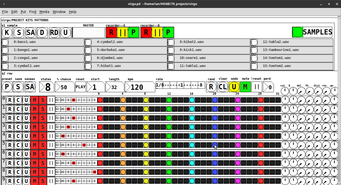
virgo:[virgo/PROJECT KITS PATTERNS]
- PROJECT[KITS PATTERNS]
- $1:[KITS sample]
- GUI
- K: openpanel to load a previously saved *.txt (text object) kit of samples; on loadbang the default.txt kit is loaded
- S: save the current set of samples to the most recently opened *.txt (kit) preset
- SA: saveas a *.txt of the current set of samples
- D: foldererpanel a sample directory to load the first (alphabetically) 16 samples into the 16 slots
- RD: load a random kit from the [text samples] object where the samples where previously loaded via the "SAMPLES" bang on the right
- U: undo; return to the previously opened or saved *.txt kit, so not the previously randomized
- MASTER: master gain
- (recorder~: of the total audio~ out)
- record
- ||: pause; either recording or play;
- play: output is combined with the sequencer output just before MASTER out to [dac~]
- SAMPLES: folderpanel to load a (recursive) directory of samples for generating random kits
- ABSTRACTIONS
- $1: sample
- bang: openpanel to locate and load a sample for a track
- canvas: filename of the opened sample; filenames are indexed in alignment with track indices in the PATTERNS section
- $1: sample
- GUI
- $2:[PATTERNS row]
- GUI
- P: openpanel to load a previously saved *.txt (pattern) preset file; on loadbang the default.txt pattern is loaded; the preset file includes the beat, pattern, and effect settings for the row
- S: save the current pattern to the most recently opened pattern .txt
- SA: save as (self-explanatory)
- states: the number of possible states [2..8] of each beat;
- %: weight; chance of a beat being randomized; not chance of what it will result in; ex. 100% implies all beats are randomized ; random beats result in a value)gain) between 1 and states-1
- PLAY(reset): play the pattern from "start" or on stop reset all playheads to start
- start: which beat to start the playheads on
- length: how many beats to play [+/-32]; if negative the playheads will play in reverse/from right to left
- bpm: beats-per-minute
- rate: to change the rate of play (ie metro times) by the listed factor for all playheads
- R: randomize the total pattern (incl period and beats, but not the effect settings; beats of 1/32 are not included in the possibilities)
- CL: clear, set all beats to "0", i.e. off
- U: undo random; return to the previously opened or saved preset, ie. not the previous random one
- M: mute all tracks; the playheads continue moving but audio does not come out of any track
- ||:pause all playheads; play will resume from that location when un-paused
- per: period; if 0=randomizes the period, >0 sets the period to be used for all beats
- Edit Mode
- Check the [E] to enter edit mode (to cut, copy, or paste selected regions of the pattern)
- Entering edit mode will pause the playing of the pattern
- Play, if doing so beforehand, will resume on leavng edit mode
- The top-left most beat of the pattern grid will be selected when first entering edit mode
- Single-click a beat to select the top-left corner of the region you wish to cut or copy
- Double-click a beat to select the bottom-right corner
- You may not double-click a beat "less than" the single-clicked (top-left) beat and vice-versa
- Click [CL] to clear your selection (i.e. start over)
- The selected region will turn to dark colors
- If only one beat is selected it will be the only one darkened
- Click the operation (bang) you wish to perform, either cut [CU] or copy [CP]
- Then, hold down the CTRL key and click the top-left corner of where you want to paste the region
- The clicked cell will turn white
- And click [P] to paste the region
- Cut and copied regions may both be pasted multiple times
- The difference being, cutting sets the values (gains) for the originating region to "0"
- Click [UN] to undo either the cut, copy, or paste operation
- Undoing cut will return the gains from 0s to their original value
- Check the [E] to enter edit mode (to cut, copy, or paste selected regions of the pattern)
- (effect settings applied to all tracks)
- co: vcf-cutoff
- Q: vcf-q
- del: delay-time
- fb: delay-feedback
- dist: distortion
- reverb
- gn: gain
- ABSTRACTIONS
- $1: [row (idx) b8] (()=a property not an abstraction)
- GUI
- (index): aligns with the track number in the KITS section
- R: randomize the row; same as above, but for the row
- C: clear the row, i.e. set all beats to 0
- U: undo the randomize; return to the originally opened one, ie. not the previous random one
- M: mute the row, so no audio plays, but the playhead continues to play
- S: solo the row
- (beat): unit of the beat(period); implying metro length (as calculated with the various other parameters);1/32,1/16,1/8, etc.
- (pattern): the pattern for the row; single-click on a beat from 0 to 8 times to increment the gain of that beat as a fraction of 1 rms, where resulting rms=value/states; black is rms=0; if all beats for a row =0 (are black) then the switch for that track is turned off; double-click it to decrement it
- (effects-per-row): same as above, but per-row, ex. first column is vcf-cutoff, second is vcf-q, etc.
- ABSTRACTIONS
- $1: b8 (properties:row column)
- 8-state bang: black, red, orange, yellow, green, light-blue, blue, purple; representing a fraction of rms(gain) for the beat
- $1: b8 (properties:row column)
- GUI
- $1: [row (idx) b8] (()=a property not an abstraction)
- GUI
- $1:[KITS sample]
Credits: The included drum samples are from: https://www.musicradar.com/news/sampleradar-494-free-essential-drum-kit-samples
p.s. Though I began working on cut-copy-paste, it began to pose a Huge challenge, so backed off, in order to query the community as to 1) its utility in the current state (w/o that) and 2) just how important including it really is.
p.p.s. Please, report any inconsistencies (between the instructions as listed and what it does) and/or bugs you may find, and I will try to get an update posted as soon as enough of those have collect.
Love and Peace through sharing,
Scott
 posted in patch~
Question about Pure Data and decoding a Dx7 sysex patch file....
For the Blofeld editor, well, it's a one way communication editor(for now), the editor only sends data to Blofeld, I can not change a parameter directly on Blofeld and then the editors parameter follows. I didn't do that yet, but it's on the to do list.
In my last post, when I refer to a sound dump, it's the same as a patch dump. But what I did there was only to start the sound dump on Blofeld by sending the "request sound dump" sysex string from Pd to Blofeld, to dump the current sound from Blofeld and then receive the sound dump in Pd. I did not try to decode the sound dump to get the individual parameters. So can't use that for the Dx7 approach.
I did get an idea from your posts, though, how I might be able to "backwards engineer" the sysex patches from Dx7:
- Use the free Dexed dx7 and export a patch sysex dump for reference.
- Then use the same patch and change ONE single parameter and export the patch as sysex dump.
- Compare the two sysex dumps and see which values have changed. The value changed is the parameter I am looking for. I can then assign it to a fader in my Dx7 editor.
- Do it a few times with a few different parameters, until I find a pattern. Or just do it for every single parameter, to be on the safe side......
(Dexed Dx7 editor/Vst - https://www.kvraudio.com/product/dexed-by-digital-suburban/downloads)
I know, it's not the smartest way, but it worked for Blofeld and since this is "only" around 150 params in total it should be manageable, as a weekende project ")
About the 32 voices, ahh yes, you are probably right, it's the amount of presets, not actual polyphonic voices. Would love to get that working too, to get all 32 voices/presets of a voice card dump. There are a lot of them around.
Thanks again. I actually though sysex messages for full patch dump was more complicated. If all parameters are just individual numbers in the sysex string, it's doable, just a bit time consuming.
 posted in technical issues
Question about Pure Data and decoding a Dx7 sysex patch file....
Hey Seb!
I appreciate the feedback
The routing I am not so concerned about, I already made a nice table based preset system, following pretty strict rules for send/recives for parameter values. So in theory I "just" need to get the data into a table. That side of it I am not so concerned about, I am sure I will find a way.
For me it's more the decoding of the sysex string that I need to research and think a lot about. It's a bit more complicated than the sysex I used for Blofeld.
The 32 voice dump confuses me a bit. I mean most single part(not multitimbral) synths has the same parameter settings for all voices, so I think I can probably do with just decoding 1 voice and send that data to all 16 voices of the synth? The only reason I see one would need to send different data to each voice is if the synth is multitimbral and you can use for example voice 1-8 for part 1, 9-16 for part 2, 17-24 for part 3, 24-32 for part 4. As an example....... Then you would need to set different values for the different voices. I have no plan to make it multitimbral, as it's already pretty heavy on the cpu. Or am I misunderstanding what they mean with voices here?
Blofeld:
What I did for Blofeld was to make an editor, so I can control the synth from Pure Data. Blofeld only has 4 knobs, and 100's of parameters for each part.... And there are 16 parts... So thousand + parameters and only 4 knobs....... You get the idea ")
It's bit of a nightmare of menu diving, so just wanted to make something a bit more easy editable .
First I simply recorded every single sysex parameter of Blofeld(100's) into Pure data, replaced the parameter value in the parameter value and the channel in the sysex string message with a variable($1+$2), so I can send the data back to Blofeld. I got all parameters working via sysex, but one issue is, that when I change sound/preset in the Pure Data, it sends ALL parameters individually to Blofeld.... Again 100's of parameters sends at once and it does sometimes make Blofeld crash. Still needs a bit of work to be solid and I think learning how to do this decoding/coding of a sysex string can help me get the Blofeld editor working properly too.
I tried several editors for Blofeld, even paid ones and none of them actually works fully they all have different bugs in the parameter assignments or some of them only let's you edit Blofeld in single mode not in multitimbral mode. But good thingis that I actually got ALL parameters working, which is a good start. I just need to find out how to manage the data properly and send it to Blofeld in a manner that does not crash Blofeld, maybe using some smarter approach to sysex.
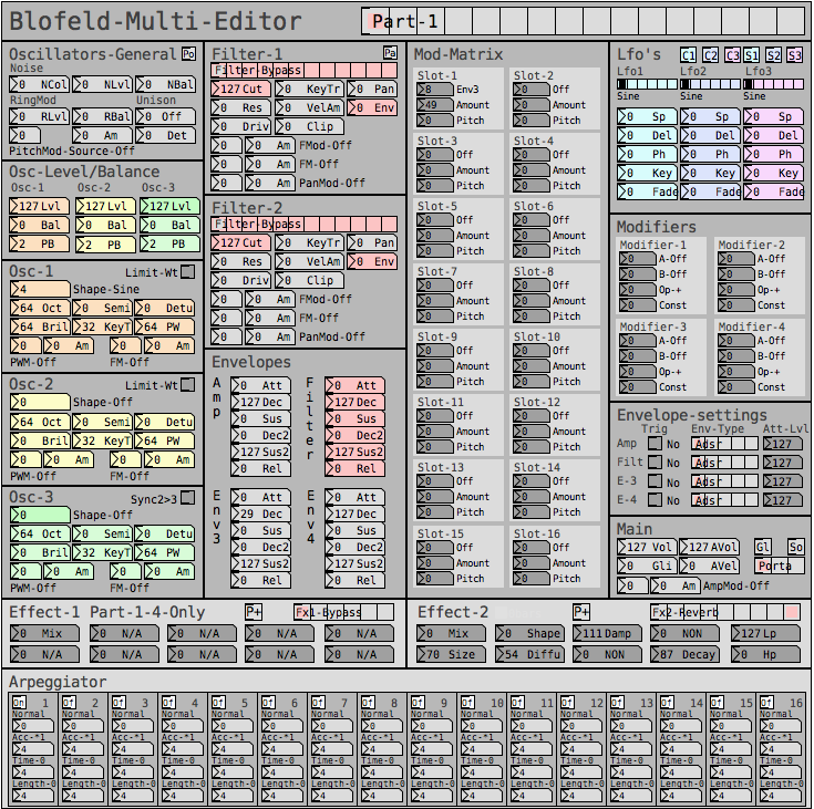
But anyway, here are some snapshots for the Blofeld editor:
Image of the editor as it is now. Blofeld has is 16 part multitimbral, you chose which part to edit with the top selector:
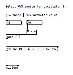
Here is how I send a single sysex parameter to Blofeld:
If I want to request a sysex dump of the current selected sound of Blofeld(sound dump) I can do this:
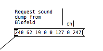
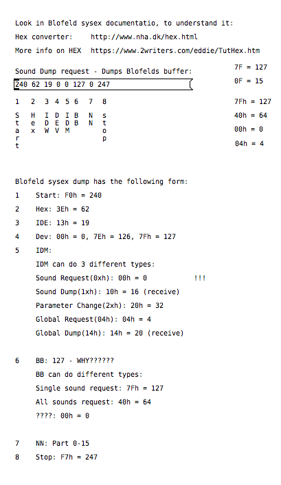
I can then send the sound dump to Blofeld at any times to recall the stored preset. For the sound dump, there are the rules I follow:
For the parameters it was pretty easy, I could just record one into PD and then replace the parameter and channel values with $1 & $2.
For sound dumps I had to learn a bit more, cause I couldn't just record the dump and replace values, I actually had to understand what I was doing. When you do a sysex sound dump from the Blofeld, it does not actually send back the sysex string to request the sound dump, it only sends the actual sound dump.
I am not really a programmer, so it took a while understanding it. Not saying i fully understand everything but parameters are working, hehe
So making something in Lua would be a big task, as I don't know Lua at all. I know some C++, from coding Axoloti objects and VCV rack modules, but yeah. It's a hobby/fun thing I think i would prefer to keep it all in Pure Data, as I know Pure Data decently.
So I do see this as a long term project, I need to do it in small steps at a time, learn things step by step.
I do appreciate the feedback a lot and it made me think a bit about some things I can try out. So thanks
posted in technical issues
Having lots of switches into Pd
@alexandros thanks, it all works!
I merged the codes for in and outs and also changed so you can set up all of the pins with arrays (as you did in the latter code). Then you can set up the pins in any order.
Here is the Arduino code. Do you spot any errors I may have introduced?
//number of elements in array need to match for() cycles
int pinsIn[4] = {2, 7, 10, 11};
int pinsAnalog[3] = {0, 2, 3};

int pin = 0;
int val = 0;
// some random pins
int pinsOut[4] = {3, 4, 5, 6};

void setup()
{
  //set up a total of pins for input (has to match number of elements in array)
  for(int i = 0; i < 4; i++)
  pinMode(pinsIn[i], INPUT);

  for (int i = 0; i < 4; i++) {
    pinMode(pinsOut[i], OUTPUT);
    digitalWrite(pinsOut[i], LOW);
  }

  Serial.begin(115200); // perhaps use a faster baud rate
}

void loop()
{
  Serial.print("knobs"); // use "knobs" as a keyword so you can receive
  // the knob values as a list with a [r knobs] in Pd
  for(int i = 0; i < 3; i++){
    unsigned int knob = analogRead (pinsAnalog[i]);
    Serial.print(" "); // first print a white space to separate the "knob" keyword from the values
    // and the values from each other
    Serial.print(knob); // then  print the actual knob value
  }
  Serial.println(); // finally print a newline character to denote end of data for keyword "knobs"

  // the same technique applies to the switches too
  // receive the switch values as a list with [r switches]
  Serial.print("switches");
  for(int i = 0; i < 4; i++) {
    int switchVal = digitalRead(pinsIn[i]);
    Serial.print(" ");
    Serial.print(switchVal);
  }
  Serial.println();

  //handle digital outputs
  if (Serial.available()) {
    static int temp;
    byte in = Serial.read();
    if (isDigit(in)) {
      temp = temp * 10 + in - '0';
    }
    else if (in == 'p') {
      pin = temp;
      temp = 0;
    }
    else if (in == 'v')  {
      val = temp;
      temp = 0;
      digitalWrite(pinsOut[pin], val);
    }
}
}
In Pd I was not able to use [r switches] or [r knobs] but had to use [route]. Is this the correct way to use [serial_print]?
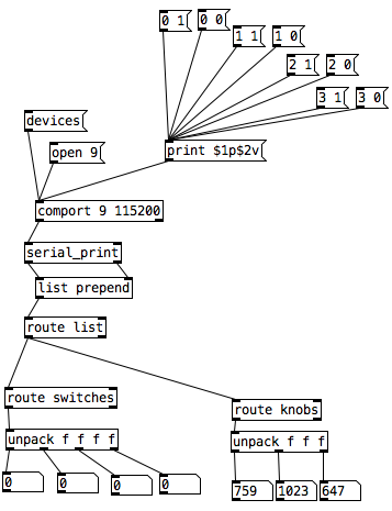
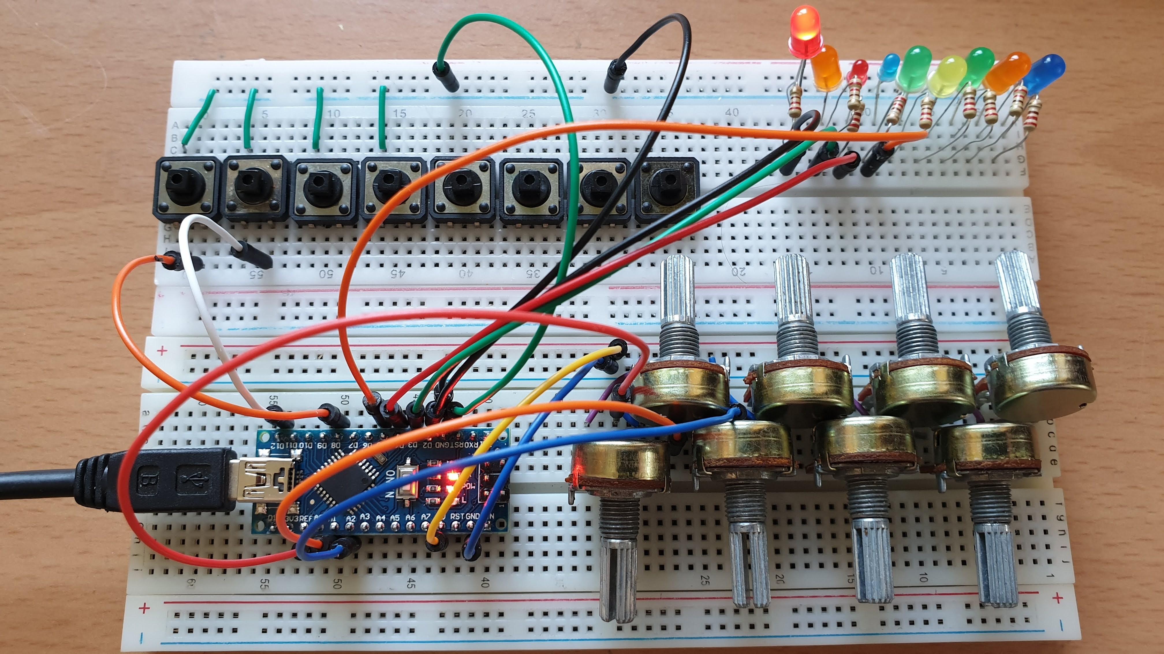
And here it is on the breadboard:
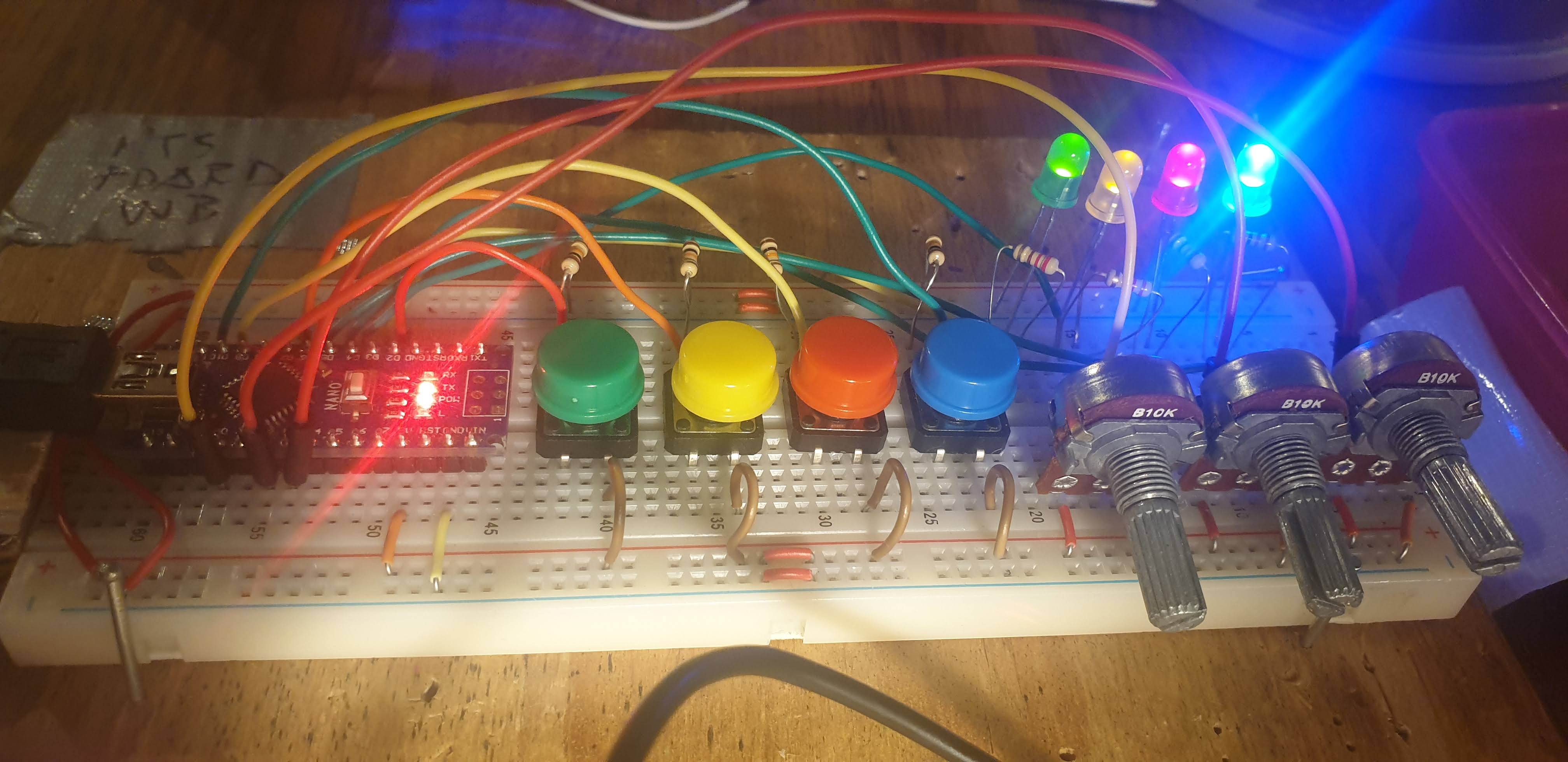
posted in I/O hardware diy
Having lots of switches into Pd
I would suggest to not mix the analog values with the digital ones. The first code could be changed to the following (using Serial.print() with the [serial_print] abstraction):
void setup()
{
  for(int i = 2; i < 14; i++)
  pinMode(i, INPUT);
  Serial.begin(115200); // perhaps use a faster baud rate
}

void loop()
{
  Serial.print("knobs"); // use "knobs" as a keyword so you can receive
  // the knob values as a list with a [r knobs] in Pd
  for(int i = 0; i < 6; i++){
    unsigned int knob = analogRead (i);
    Serial.print(" "); // first print a white space to separate the "knob" keyword from the values
    // and the values from each other
    Serial.print(knob); // then  print the actual knob value
  }
  Serial.println(); // finally print a newline character to denote end of data for keyword "knobs"

  // the same technique applies to the switches too
  // receive the switch values as a list with [r switches]
  Serial.print("switches");
  for(int i = 2; i < 14; i++) {
    int switchVal = digitalRead(i);
    Serial.print(" ");
    Serial.print(switchVal);
  }
  Serial.println();
}
As for writing to several outputs you need to set which output you want to write to and then the value you want to write. Here's an example that writes to several different digital outputs:
int pin = 0;
int val = 0;
// some random pins
int pins[4] = {3, 4, 5, 6];

void setup() {
  for (int i = 0; i < 4; i++) {
    pinMode(pins[i], OUTPUT);
    digitalWrite(pins[i], LOW);
  }

  Serial.begin(115200);
}

void loop() {
  if (Serial.available()) {
    static int temp;
    byte in = Serial.read();
    if (isDigit(in)) {
      temp = temp * 10 + in - '0';
    }
    else if (in == 'p') {
      pin = temp;
      temp = 0;
    }
    else if (in == 'v')  {
      val = temp;
      temp = 0;
      digitalWrite(pins[pin], val);
    }
}
With the code above you can send messages like this one print $1p$2v in Pd to the [comport] object. $1 is the number of the pin you want to light up starting from 0 and incrementing by 1 (so the first pin used which is pin 3 in the Arduino code would be 0 in the Pd patch), and $2 is the value, 0 or 1.
Note though that in the first code (and the code you posted), you're using all digital pins as inputs so there's no pin left to use as output. If you want to combine these two chunks of code you'll have to use less pins as inputs and leave some to be used as outputs.
posted in I/O hardware diy