What's your favorite noisegate?
@svanya Use the MultibandNoiseFilter. The left inlet is audio, the right sets how much noise to remove. The outlet is the filtered audio,
Attach a slider to the right inlet with a range from 0 to 2. That ought to be a wide enough range that you can adjust it to clean things up without also destroying the voice signal.
How it works is pretty simple, but difficult for me to put into words. If you are interested in how it works, take a look inside NoiseFilter and NoiseDetector.
NoiseFilter pretty much just attenuates the audio based on the noise level that it finds. How it finds the noise level is the trick.
It uses the subpatch dBr to find the level of the signal, then passes that through a highpass filter and a low pass filter. Those two determine what is seen as "static" noise. Anything that changes slower than the high pass is static noise. Anything that changes slower than the lowpass is signal. Anything that changes faster than the lowpass is noise.
Changing the value of the highpass determines how fast things get filtered out - if it "eats" your long notes, then you need to make the cutoff of the high pass lower.
Once it has the filtered level, it takes the absolute value of the variations in the level and compares them to the selected noise reduction level. Anything below the desired level closes the gate. Since this causes a pulsing signal, theres's a lowpass to smooth it out.
Now, you have a signal proportional to how much noise is in your signal. The more the noise, the lower this proportional signal is.
Multiply that with your original audio, and it attenuates the audio according to how much noise there is.
The rest is splitting it into bands so that you don't attenuate everything at once, but just the frequencies where there's noise.
 posted in technical issues
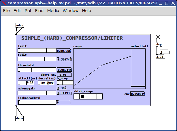
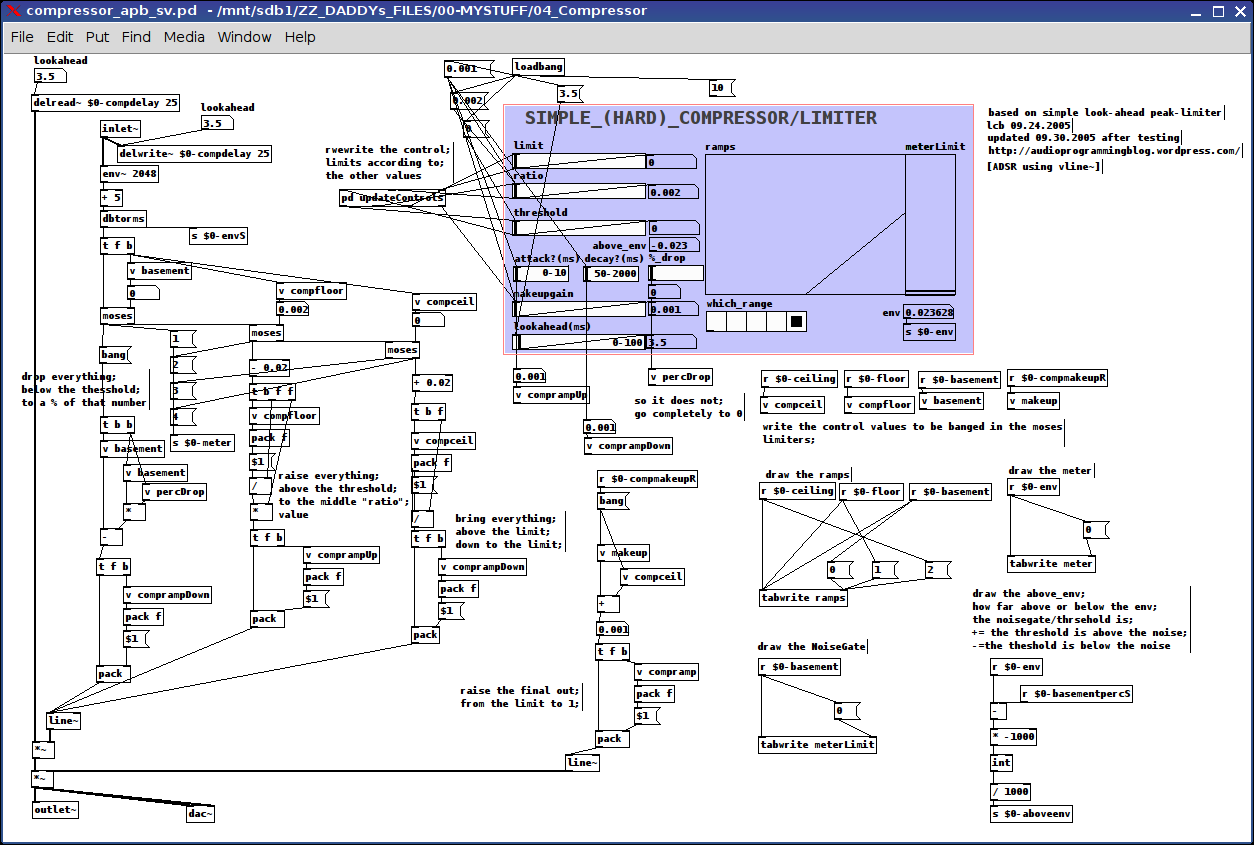
Little help please: building my own compressor (updated below...)
@whale-av
'Some compressors (AKG were the first I remember) introduce a tiny delay to the main signal so as to introduce the required compression before the signal arrives (catch all transients). That is called "feed forward compression"':
I incorporated this as a "lookahead" passing a variable to the initial delay line;
'You will also see (on manufactured units) "attack" (time for compression to ramp up....... approx.? 0-10ms.... to allow short transients to pass more naturally... un-"chopped") and "release" (the time to slowly release the compression after the signal has dropped below the threshold again....... 50ms-2sec.... usually about 300ms is good for vocals)';
I included these and the numbers you suggest as the ramp values for attack: from below threshold to the "ratio" value and decay for below-threshold to a percent between that value and 0 (think this is a good option, because it sounds really screwy when it drops to nothing) and for those values above-the-limit dropping to the limit.
'bad microphone technique.': For example?
'knee': how to add this? via ADSR envelope? not sure how I would go about make the curve (soft knee)...suggestions?
'your patch looks like a spaghetti omelette to me at the moment!': I was sorry to hear this for two reason: the pain you must have/are undergoing and that perhaps my patch was a "mess". (not time to be sensitive tho. so pushed on.) Hope all is doing better for you.
Regarding this update:
ALL:
the controls:
limit, ratio, threshold, and makeup gain are all calibrated on the fly using the updateControls subpatch which scales the "left" and "right" values of each control (using range messages) accordingly
all signals are grouped into 4 categories using the moses's: below-threshold, above-threshold-below-ratio, above-ratio-below-limit, and above-limit
limit:
"above limit" signals are brought down to this limit
ratio:
"above ratio-below limit" signals are left untouched
threshold:
"above threshold-below ratio" are brought up to the ratio value
above_env:
Is to be used as a noisegate meter if the value is a positive number then the threshold is above the env~, i.e. background noise
attack/decay and ?:
? because I am not certain, if in the context of compressors I have applied these concepts correctly:
attack: the length of time it takes to make the upward ramps, 0-10 ms
decay: the length of time it takes to make the downward ramps, 50-2000 ms
% drop:
what percent between 0 and the threshold the signal is to be decreased, in other words, filter the noise completely or just a little bit, 100% drops it to 0, 1% drops it 1% below the threshold (fyi: I found dropping it completey to 0 sounded "wrong")
makeup gain:
the amount to increase the final output, between the limit and 1
lookahead:
how much time the delay line should be between 0-100 ms (have NO idea what range this "should" be, so input is requested)
ramps:
graphical representation (from left to right) of the the threshold, ratio, and limit on a 0 to 1 scale
meterLimit:
the env~ (really just a vu) and a line representing where the threshold is on that same scale (0 to 1) in order to better judge where to set the values
which_range:
A meter showing from left-to-right where the current sound is (to be used as simple guide to setting the parameters): silence, above silence-below threshold, above threshold-below ratio, above ratio-below limit, and above limit
I DO hope this is useful to someone/anyone. And ,if nothing else, might act as a guide to others addressing this pretty-darn challenging concept.
I have included some features which I have not seen other compressors include, while there are others I might or probably will/should include later, ex. a soft knee on the curves.
All opinions/insight/daily feelings/usage of/ etc. etc. etc. are very welcome.
Peace and may your days, hearts, minds, and loved ones be over-flow-ering with Music.
-svanya
p.s. will probably move this lateron to the abstractions section, once I am certain everything is working as planned.
 posted in technical issues
DIY2 - Effects, Sample players, Synths and Sound Synthesis.
@unstable said:
Hey I got a question. in the compression patches I can kind of get my head around the amp factor section. But I don't get any of the att/rel section. Can anyone explain what that sgn~ (signum) is/does ? Secondly I can see the table is effected by the release but not really on the attack. I can hear the attack. The block size is 2. I'm guessing if the default block size is 64 samples then 2 means 128?? Or is it actually 2 ? This outputs a frequency between 0.019 and 57 into a VCF along withe the original amp factor. Any advice ?
ok, so the [amp-factor] stage is giving the amplitude of the signal, scaled according to our threshold and ratio settings. This will either be positive if the amplitude is rising, or negative if it's falling.
next we go into the [att-rel-filtering] section, where we separate the attacks (positive) from the releases (negative)
[block 2] really does mean that the blocksize is only 2 samples. This is so that the [tabsend~] and [tabreceive~] objects deal with packets of two samples at a time,
giving us a sample delay between the input signal and the signal received by [tabreceive~]. If the blocksize were the default of 64, then we would have a 64 sample delay, and our compressor would not work at all well.
sgn~ just gives the sign of the signal, so -1 for negative numbers and 1 for positive ones. note that we are dealing now with just the AMPLITUDE of the signal, which has been scaled in the [amp-factor] section so that rising amplitude (ie, attack) is positive and falling amplitude (release) is negative.
that is then split apart using [max~ 0] with attack sent to the left outlet and release sent to the right outlet. The attack and release stages are both scaled separately (attack scaled by 0.019 to 57, and release by, i think, 0.00019 to 5.7) (and i don't know exactly WHY 57 was chosen, i'm sure the patch would work just as well with 50 or 60)
then we go through the [vcf~]. Although vcf~ is normally used to shape the frequency content of a wavform, in this case, it has a different use. It is smoothing the amplitude signal. So, if we set a fast attack, then the vcf~ will have a cutoff of 57hz, and our compressor will attack within 20ms. if we set a slow attack, then the vcf~ will have a frequency of 0.019hz, and the compressor will take a few seconds to fully attack.
finally, the original signal is multiplied by the compression factor, and sent along its way.
There are some quick mods you can do to this patch, too. A sidechain compressor, essential for any sort of 'french' electro sound, can be made by adding another inlet~ for a second audio signal, and taking the inverse of the compression factor, like this:
[pd att-rel-filtering]
|
[-~ 1]
|
[*~ -1]
and then multiply your second signal by that.
also, it is fun to take the compression factor output to its own [outlet~] and use it as a modulation source for filter cutoffs for synth sounds, etc.
anyway, hope that clears things up a bit?
have fun!
 posted in patch~
FFT freeze help
[rfft~]/[rifft~] makes the assumption that you only intend to work with real signals (i.e. no imaginary part). [fft~]/[ifft~] will work with real and complex signals (real and imaginary part).
With real signals, if you do a spectral analysis from 0 Hz all the way up to the sampling rate, you'll find that the spectrum between Nyquist and the sampling rate is a mirror image of the spectrum between 0 Hz and Nyquist. (When you think about it, it makes sense; a frequency above Nyquist will alias below to another frequency, so to a digital signal both those frequencies are really the same thing.) Since they are just mirror images, it is computationally pointless to calculate the second half of the spectrum after calculating the first half, because we already know it. So [rfft~] doesn't compute the frequencies above Nyquist, and [rifft~] assumes the spectrum should be mirrored and so doesn't calculate an imaginary part for the synthesized signal. In other words, they're more efficient.
Complex signals, on the other hand, may not have a mirrored spectrum. In that case, you need to use [fft~]/[ifft~] to calculate the full spectrum. Music signals are typically real, though, so for most situations it is best to use [rfft~].
Also, just to be clear, the real or complex signals I'm talking about here are in the time domain. In the frequency domain they will always be complex.
 posted in technical issues
Better sounding guitar distortion ... beyond \[clip~\] and \[tanh~\]
Also quite glad to see this! This has become one of my favorite threads of the forum. It covers a lot of ground, and it's great to see your hard work and perseverance payoff here. Cheers too you, nau!
@nau said:
The BJT gains are bound to my 'signal amplitude policy' : input file or audio source and output should never clip. These gains can be seen as follows : the first one (before the clipper) adjust 'how early' distortion occurs, and the second one gives the distorted signal a boost in order to give similar subjective level than dry signal.
The values were found empirically.
This might be where I have the biggest issue, though the article doesn't make it so clear, either. In the article, it shows the frequency response of the BJT stage as having about a 36 dB boost in the pass band. That amounts to multiplying the signal by about 63. And, if you want to get really technical, the waveshaper in the article clips at +/- .6, so you'd have to add about another 4.5 dB to make up for that. You're using much lower values. This is what I was talking about earlier when I said you should really crank the input to [tanh~] to get some serious distortion, and the DS-1 isn't a baby's distortion pedal.
Now, the article also says that the second BJT stage is really to boost the signal back up for the subsequent load. Since we're not sending this into other circuits here, I think the dB boost of the second BJT should be ignored. Also, you don't need to calculate the boost into the filter coefficients. That's only useful for plotting. You can just use [*~] before or after the filter do accomplish it.
So basically what I'm saying is, there should be a boost of about 40 dB ([*~ 100]) as part of the first BJT stage, and no boost for the last one. Then you can really break some teeth with this distortion.
- when switching between upsampled or not upsampled processing, the difference is barely noticeable (maybe the upsampled one has more highs, but that is the exact contrary of what I would expect). Does someone see what I am doing wrong, if this is the cause of this perceptual draw ?
As mod said, it's not so much more highs as less lows, and those lows are a result of aliasing. To my ears, the upsampled version sounds less muddy. (By the way, in your upsampled portion, you have a different argument for the second [DS1-bjt_stage~]. Making them equal makes the difference even less noticeable, and draws more attention to the mud than the highs.)
- the transfer curves can be seen in the patches, but are always slightly different than the one showed in the article. But I have been very careful when calculating coefficients and I don't really think they are wrong. Would there persist a difference between [filterplot.mmb] and traditional Matlab-like graphs ?
Yes, there is a difference, but it's not a Matlab thing. It's the choice of the logarithmic scaling in the x-axis. The article uses powers-of-ten as equal distances. Mine uses [mtof] for the scaling, so that a semitone, octave, or whatever musical interval is the same distance. Also, I made an adjustment so that everything between 0 and about 20 Hz (at 44.1k) gets squashed in the leftmost 10% of the graph. If I didn't to that, then about half the plot would be taken up with frequencies below the audible range.
- The DS1-tone_stage helpfile has been written by Maelstorm, and the response curve shows no gain value above 0db. Nevertheless the tone knob, when pushed, can lead to signal amplitude beyond [-1 1]... I can't figure out how a signal can have all its discretised frequencies pulled down and still exhibit peaking. Should I read more about the subject (is there a name for this symptom ?), or is there an error in my patch ?
This has nothing to do with your tone stage. It's because of the passband ripple in the Chebychev filters. The IEM Chebychev filters have a 1 dB ripple, though I don't actually know if that means +/- 1 dB or +/- .5 dB. Either way, it's creating a boost at some frequencies, and pushing the output down by 1 dB should keep it below [-1, 1]. This could also be contributing to the highs, as the ripple is typically more pronounced near the cutoff frequency.
- is my 'signal policy' perfectible ? I want the output signal never to clip, so I multiply the output by 0.4 in such a way that when Tone and Dist are full right but Level is medium the signal never clips.
The output from [tanh~] will never clip, so as long as you make up for the ripple and don't boost the second BJT stage, you should be fine.
Just one more thing to add for now, and that is you're doing too much in the upsampled portion. The only thing that needs to be in there is the non-linear function ([tanh~]) and the anti-aliasing filters. Everything else is linear and doesn't benefit from upsampling, so it's just creating more computational load. So it should look more like this:
[*~ 100]
|
[DS1-bjt_stage~ 1]
|
[DS1-opamp_gain~]
|
[*~ 8]
|
[pd upsample]
|
[DS1-tone_stage~]
|
[DS1-bjt_stage~ 1]
|
[*~ .891] <-- 1 dB cut
And [pd upsample] should look like this:
[inlet~]
|
[lp10_cheb~ 18000] [block~ 64 1 8]
|
[tanh~]
|
[lp10_cheb~ 18000]
|
[outlet~]
Okay, that turned out to be more words than I expected. But we're getting into DETAILS here! Again, nice work, nau.
posted in technical issues
Better sounding guitar distortion ... beyond \[clip~\] and \[tanh~\]
Hi there,
here it is... a handy workbench to emulate a distorsion pedal following the article https://ccrma.stanford.edu/~dtyeh/papers/yeh07_dafx_distortion.pdf and Maelstorm's best support and advices.
A free of rights soundfile is joined, in such a way that if we want to interact everyone has the same workbench basis.
The file to be opened is DS1-workbench.pd. Some abstractions (several made by Maelstorm) are joined. It should work on extended.
Link : http://www.sendspace.com/file/2stec8
The BJT gains are bound to my 'signal amplitude policy' : input file or audio source and output should never clip. These gains can be seen as follows : the first one (before the clipper) adjust 'how early' distortion occurs, and the second one gives the distorted signal a boost in order to give similar subjective level than dry signal.
The values were found empirically.
I have several interrogations:
-
when switching between upsampled or not upsampled processing, the difference is barely noticeable (maybe the upsampled one has more highs, but that is the exact contrary of what I would expect). Does someone see what I am doing wrong, if this is the cause of this perceptual draw ?
-
the transfer curves can be seen in the patches, but are always slightly different than the one showed in the article. But I have been very careful when calculating coefficients and I don't really think they are wrong. Would there persist a difference between [filterplot.mmb] and traditional Matlab-like graphs ?
-
The DS1-tone_stage helpfile has been written by Maelstorm, and the response curve shows no gain value above 0db. Nevertheless the tone knob, when pushed, can lead to signal amplitude beyond [-1 1]... I can't figure out how a signal can have all its discretised frequencies pulled down and still exhibit peaking. Should I read more about the subject (is there a name for this symptom ?), or is there an error in my patch ?
-
is my 'signal policy' perfectible ? I want the output signal never to clip, so I multiply the output by 0.4 in such a way that when Tone and Dist are full right but Level is medium the signal never clips. Pushing further Level will cause 'unwanted output distortion'. Of course I'm thinking about modifying this final output gain in such a way that it is bound to Level or anything else. This is away from the original circuit, but is legitimated by numerical audio considerations.
Thank you,
Nau
 posted in technical issues
Granular synthesis in realtime
Hi there!
Lots of fine and talented ladies and gentlemen here, i feel i need to finally stop lurking and get my concept together.
I'm banging my head around a concept of realtime granular modulation to the incoming signal.
Every granular synth i have encountered is built upon samples - either recorded or read from a disk.
I would like to make grains out of heavily timestretched first couple of ms of the incoming signal and then continue with the rest of the signal, probably fed from a continuously refilled buffer.
As I'm only a humble piano player the idea of making two tables that somehow manage to synchronize the out-spitting of the little grain-building chunks of audio makes me wonder if there isn't any widespread solution to my problem?
my signal would need to be timestretched at least 8 times its size, so I think there should be plenty of computational time to spare.
For added value I plan to implement beat synchronization so on every next beat the grain catches up on the incoming signal (scraps or saves the buffer and fills it anew)
So putting a long story short: how to feed a realtime signal into a variable length grain window, saving the residual realtime signal somewhere else?
should the timestretching be constant or is it possible to modulate this also?
I hope i made myself clear and someone will offer a helping hand so I can start coding. Of course if I succeed I will share the results ")
Nikola Kolodziejczyk
http://music.thinkbay.net
 posted in technical issues
Pitch changes using \[vd~\]
...but don't forget, there is a "point" (or frequency or refresh-rate) at which calculations via (audio)-signals are faster than the data-wise calculations...
I wonder when this exactly is the case. I have no Mac so I can't directly measure the CPU-load... but using audio often helped to reduce dropouts.
...ANd why or how?! Well, I don't know since I'm not into C-programming or whatever.. But I guess there must be any kind of pre- or post-message sticking to the data-signal (apart from all those "bang", "float" or "list" ) which roughly is left out at audio-signals.
If there is nothing like "audio" for audio-signals (like "bang" for "data-bang"), then the usual premessages like "float", "list"... would suffice.
So in general (looking at just one action like one value of the audio-signal-vector or one "banged data-action") there is more going on at data-signals then at audio-signals.
So they are calculated faster if the data-refresh-rate exceeds a certain frequency. Any other theories?!
Flipp
 posted in technical issues
Swept sine deconvolution
Hello Katja and lead,
Katja - the new version of the sweep code is great!!!
I have taken some time at work now to calculate the exact exponential of 2 to have 3s, 6s, 12s and 24s sweep and this is included in the attached zip file (I have altered your patch, Katja).
regarding the generated sweep there are still two things to note:
-
at the end you have this 'bleep effect' and I agree with Katja that we can create a very short (64 sample) smooth fade-out
-
by the end of the sweep you get a frequency modulation (oscillation mainly) that is a bit strange; this can be due to the fact that I am listening on headphones the signal and I can have an acoustic "allucination" (typical when listening a mono test signal in a stereo set) or due to something in the code...
comparing it to the signal at this link it doesn't appear to me
http://www.4horsemen.net/binkster/tracks/track06.zip
So probably we need to have a think about the audio output of the patch.
Sweep signal are mono signal and they are commonly reproduced through mono or multi channel mono systems (at least for room acoustics measurements).
Then regarding the convolution, It would be nice to create a self-working measurement environment in PD (so provide convolution as well) but let's discuss what we can do.
I will investigate a bit more the theory behind the deconvolution of the recorded signal with the inverse of the "pure" text signal and see if we can run the convolution in time domain only instead of occupying the frequency domain.
This is really exciting for me
Thank you very much for your effort in this
Bassik
 posted in technical issues
FFT and DWT for any kind of signal (25Hz, 200Hz, 1kHz) ???
Hi there,
I begin to have quite an headache wondering how I can do that properly.
I mean
I get a signal from sensors, the sample frequency is 200Hz, and I want to make FFT and DWT analyse of this signal.
Yet the [FFT~] makes analysis from sound signal, so I convert my signal to a sound with [sig~]
It makes my signal from 200Hz to 44.1kHz, all right 
The problem is that when I use [sig~] the signal doesn't put "0" between two samples, it keeps the value of the previous sample until it changes (so it's not like to raise the frequency rate and it modifies the spectrum...)
Any idea  (the same problem with DWT)
because if I can get that I just have to put a low-pass filter after the upsampling and it's allright ")
Well the REAL question is "How can i upsample this signal properly from 200Hz to 44.1kHz "
Thanks
 posted in technical issues