64 bit alternative to [hid]?
@CalBassist You could try to get the data with [comport] if it is a serial device, which is most likely.
"comport is a cross-platform object for Pure Data that allows you to read and write bytes and lists of data to /dev/tty* devices including serial port, USB-serial devices, Bluetooth-serial, etc."
Part of the problem for the developers of HID was that even for standardized devices like mice and keyboards a tailored filter had to be made, but there are hundreds of devices out there.
See the hid/HID Utilities Source/English.lproj/ folder for examples for standardized devices.
Have you tried compiling HID for 64-bit for your system?
Is there a particular device you want to use?
You might find a way by connecting through an Arduino or similar outboard processor.
There are quite a lot of projects for "wearables" where artists are trying to do such things.
David.
 posted in technical issues
64 bit alternative to [hid]?
@CalBassist If you are using osx or Linux you could try compiling hid from source, although there might be api and memory issues that could be difficult to resolve. At least a quick try will be easy.
For windows.... not so easy. In fact it didn't work in windows as a 32-bit external.
HID Source..... https://github.com/avilleret/hid
or it is in the complete source tarball for extended here.... http://puredata.info/downloads/pd-extended in pd/extra/hid
Or try a different approach......
https://forum.pdpatchrepo.info/topic/11674/hid-mousestate-in-pd-vanilla
David
posted in technical issues
error: maximum object loading depth 1000 reached
Hi
I am struggling to get [hid] external installed and running on Purr Data. I downloaded and unzipped this, https://puredata.info/downloads/hid/?searchterm=hid and placed the folder (renamed to hid) inside /Plugins, and the console says:
libdir_loader: added 'hid' to the canvas-local objectclass path
error: maximum object loading depth 1000 reached
Wth? Is it safe to delete an unused/unwanted external, to see if I can FINALLY get [hid] working?
Thanks
Brendan
 posted in technical issues
Build a MIDI controller with the Arduino, Firmata and Pure Data
Time to start contributing some knowledge back to the wonderful world that is the internet; today, a step by step nice and easy tutorial on getting started to building your own MIDI controllers with the arduino.
When researching for my ableton controller project, I didn’t find much out there about using firmata on an arduino to send data to software. The standard approach just seemed to be create the code in the arduino language, upload it to your board and hack one of those MIDI to USB cables as a bodge job way of getting the MIDI out of the arduino.
So why firmata and pure data? Well the whole idea of firmata is that you flash it to your arduino, and it throws out serial about whats going on with the arduino inputs and outputs, then you decide how the software treats the readings coming in and going out.
Theory out the way, lets build some controllers. You’ll need a few things…
HARDWARE:
An arduino and something to wire into it (for this i’ll be using a pot)
A USB cable for your arduino
SOFTWARE:
Arduino – http://arduino.cc/en/Main/Software
Pure Data – http://puredata.info/downloads
Firmata – http://at.or.at/hans/pd/objects.html#pduino
Something to patch your new controller into; like Reason or Ableton Live
- SETTING UP FIRMATA AND PURE DATA
Install Pure Data and create a folder to store all your patches somewhere. Unzip Firmata and add the files ‘arduino.pd’, ‘arduino-test.pd’ and ‘arduino-help.pd’ to your new Pure Data folder. The ‘arduino.pd’ file is the object that we use in PD for opening up communication with your arduino and routing it to PD. Done? Awesome, your software is almost set up.
- FLASHING FIRMATA TO YOUR ARDUINO
Install the latest version of arduino and open it up. Connect your arduino with the USB cable to your laptop (i’m using a macbook for this by the way). In the example patches, open up “Standard Firmata”, select your board (im using an arduino mega), and your serial port (look for tty.usbserial for use with a USB cable). Then compile and hit the upload button and your arduino is now ready to use firmata and communicate with Pure Data!
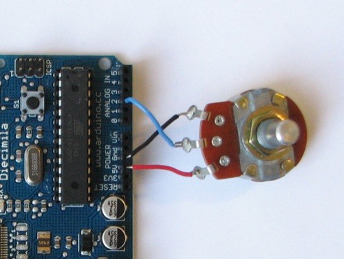
- WIRING UP A POT
Potentiometers are cool, and theres a great arduino tutorial of how to wire one up here: http://www.arduino.cc/en/Tutorial/Potentiometer
Basically, all you need to know is that there are three pins; your two outer pins govern voltage flow across the pot, meaning one has to be 5V and the other has to be ground. It doesn’t matter which, but your 5v pin is going to be where your pot reads maximum, so convention dictates this should be the right hand pin. The center pin needs to be connected to an analog in on the arduino and will read the value of the pot as it sweeps from ground (0v) to 5v.
All wired up? Plug it into your laptop and open Pure Data, we’re ready to get things talking.
- SETTING UP OUR PATCH
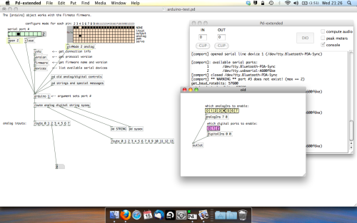
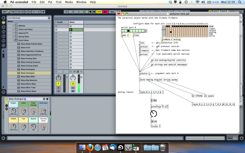
Open the example “arduino-test.pd” Pure Data patch you copied over earlier. It should look like this one…
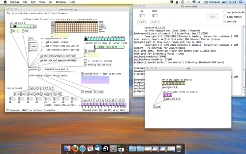
The test patch has everything we need to open a connection and enable pins. Firstly, lets delete a bunch of stuff and make our window a bit bigger. Hit Command + E to enter edit mode in Pure Data.
Ok a quick explaination; the key component here is the ‘arduino’ object. This is being drawn from the file you copied in earlier, and is what communicated with your arduino. Here we can do everything to control the arduino from opening a connection, to receiving data.
The large grid allows us to set the mode of each pin on the arduino. Remember pins 0 and 1 are reserved for Rx and Tx. I’m using analog pin 4 for this demo, so I’ve set my pin mode for pin 4 to ‘analog’.
Now we can plug our arduino in and get a reading from the potentiometer.
- ARDUINO INTO PURE DATA
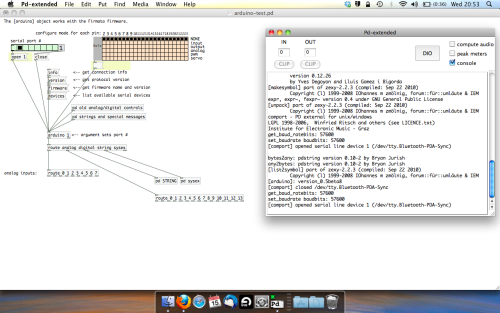
With your arduino plugged in, hit command and E to bring us out of edit mode. In our patch, click on ‘Devices’ above the arduino object and open up the pure data terminal. (That other thing that loads with PD that has all the scary code in)
The “Devices” message connected to the arduino object pings your computer to find what devices are connected and on what serial ports. Since we’re using a USB cable to connect our arduino, we’re looking for something with ‘usbserial’ in it, in this case; port 2.
Select the relevent port in the green box at the top (remember the first box is ‘0’, second is ‘1’ and so forth) and hit ‘Open’ to establish a connection. Check the terminal to see if the connection was sucessful.

Now lets check we’re getting something in. Create a number box (Command + 3) and connect it to the relevent pin on the ‘Route analog’ box at the bottom. In this case, pin 4.
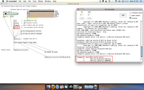
One more thing; if you’re not getting any readings in, you’ll need to click on ‘pd old analog/digital controls’ and enable your pins here too. What I tend to do in my patches is just not include the large grid but make my own ‘old pd’ controls custom to what i’m enabling/disabling to save space.
Here’s what the ‘old analog/digital controls’ subpatch looks like (pin 4 enabled)…
Come out of edit mode and check that you’ve got readings. If so congratulations! If not, troubleshoot, start with making sure your usb connection is opened, make sure all the correct pins are enabled (remember you’re counting from 0 not 1 on most of these buttons in PD, it’s just the way computers work).
- SCALING READINGS TO MIDI
So we’ve got a reading and chances are it’s to 3 decimal places between 0 to 1. No problem, create a new object (Command + 1) and type “autoscale 0 127”. This allows us to scale the input to a min and max value, in this case 0 to 127 of MIDI. Next, lets get things looking nice, create a new object and type “knob”. Connect this AFTER the autoscale object. (the knob is default set to read inputs from 0 to 127. Then create another number to display the scaled MIDI data coming out, and finally a new object and type “ctlout 1”.
It should look something like this…
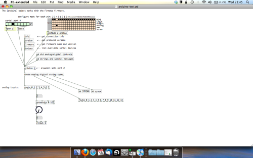
The second box should be outputing values from 0 – 127 now, and the knob giving a visual representation of your potentiometer.
Now lets patch it into ableton…
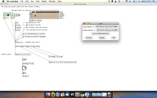
- PURE DATA TO ABLETON LIVE
Firstly, you’ll need to set up your macs IAC driver if you’ve not done this. Basically you’ll need to go into Audio/MIDI preferences and enable your IAC driver. Then create a new input and output. One for input to DAW and one for output from DAW. Google around for a tutorial on this, its really simple, a 30 second job.
After you’ve set up your IAC driver, go back to PD and go to preferences > MIDI Settings, and connect your IAC driver.
Open ableton and go to its MIDI preferences. Create a device listing for your IAC driver and enable its ins and outs into ableton like so…
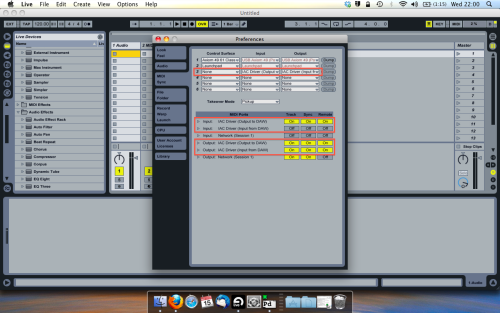
And thats it! Create an instrument and try to assign something! I’ve got it controlling the brightness of a bass sound here.
Shout out for Facu who requested this tutorial. Hopefully it’ll help some of you looking to get into this stuff and start building things but with no idea where to start.
 posted in tutorials
Ubuntu - Browsers and Puredata wont share audio output device. [SOLVED]
I found this solution and it worked ")
@sdaau_ml said:
Sorry to necro this thread, but I finally found out how to run PureData under Pulseaudio (which otherwise results with "ALSA output error (snd_pcm_open): Device or resource busy").
First of all, run:
pd -alsa -listdevPD will start, and in the message window you'll see:
audio input devices:
1. HDA Intel PCH (hardware)
2. HDA Intel PCH (plug-in)
audio output devices:
1. HDA Intel PCH (hardware)
2. HDA Intel PCH (plug-in)
API number 1

no midi input devices found
no midi output devices found
... or something similar.
Now, let's add the
pulseALSA device, and run-listdevagain:pd -alsa -alsaadd pulse -listdevThe output is now:
audio input devices:
1. HDA Intel PCH (hardware)
2. HDA Intel PCH (plug-in)
3. pulse
audio output devices:
1. HDA Intel PCH (hardware)
2. HDA Intel PCH (plug-in)
3. pulse
API number 1

no midi input devices found
no midi output devices found
Notice, how from the original two ALSA devices, now we got three - where the third one is
pulse!Now, the only thing we want to do, is that at startup (so, via the command line), we set
pdto run in ALSA mode, we add thepulseALSA device, and then we choose the third (3) device (which is to say,pulse) as the audio output device - and the command line argument for that inpdis-audiooutdev:pd -alsa -alsaadd pulse -audiooutdev 3 ~/Desktop/mypatch.pdYup, now when you enable DSP, the patch
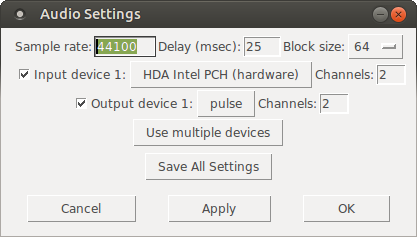
mypatch.pdshould play through Pulseaudio, which means it will play (and mix) with other applications that may be playing sound at the time! You can confirm that the correct output device has been selected from the command line, if you open Media/Audio Settings... oncepdstarts:
As the screenshot shows, now "Output device 1" is set to "pulse", which is what we needed.
Hope this helps someone!
EDIT: I had also done changes to
/etc/pulse/default.paas per https://wiki.archlinux.org/index.php/PulseAudio#ALSA.2Fdmix_without_grabbing_hardware_device beforehand, not sure whether that makes a difference or not (in any case, trying to adddmixas a PD device and playing through it, doesn't work on my Ubuntu 14.04)
 posted in technical issues
How to „read out“ time values after a bang got triggered? How to define „time windows“ in ms?
Hi there!
I’m quite new to pd but getting more and more into it as I’m trying to build a simple game/app, where users must trigger sound-samples in a certain order and (most notably) at certain points in time. The samples are triggered with bangs and since I edited them by myself, I know the exact length of every sample.
Now let us assume we have 4 samples, each of them with a length of 1200ms and each sample has its own bang to trigger it. These bangs get their input from „buttons“ which the user can hit via a graphical user interface (I built this GUI with MOBMUPLAT, a GUI-editor which interacts with Pd patches). If the bangs are triggered with exact timing, the 4 samples will add up to a musical sequence.
The first bang starts sample1 - after 1200ms the second bang (= button on the interface) shall be hit to start sample2 and so on.. it’s obvious that the user will not hit the buttons on the interface with an accuracy of single milliseconds, so here are my questions for the pd patch:
-
How can I „read out“ certain points in time, after a bang got triggered? e.g. after the first bang was hit, how much time (in ms) has passed until the second bang got hit? And can I „store“ and „recall“ these values in any way?
-
Is it possible to define a kind of „time window“ in ms? e.g. after the first bang was hit, the second bang has to be hit within 1150-1250ms to trigger something, or else (if the second is triggered too soon/late) nothing will happen..
Hope this explanation of my problem is not too complicated. Any help would be much appreciated!
 posted in technical issues
HID (Joystick-FlightStick) + GEM 2d (Cartesian) to 3d (Polar) - Visualizer
HID(FlightStick)+GEM-2d(Cartesian)to3d(Polar)-Visualizer
HID(FlightStick)+GEM-2d(Cartesian)to3d(Polar)-Visualizer.pd
Background:
Currently I am doing a lot of work (using Anduril+elvencloak+and 2 player+recorder abstractions, links to the musical pieces are at the bottom (too many to share here)) with "self-driven" remixes. (The plan is one day it will be me as I play driving those abs.)
Meaning:
I play a piece; send it thru Anduril (with randomly selected effects (14) (generally speaking correctly gain-balanced) and randomly selected fade-in/out times); and then turn elvencloak on or off (in which case I then manually manipulate the parameters).
Since the 14 effects have all been chosen because they have only 3+gain parameters (4 more are in the process of being added (body-resonance (diy2), filter (StampAlbum), noisegate (StampAlbum), & my beat-looper, they could theoritically all be controlled via one 3-d controller.
I considered (pursued) using a handheld's gyroscope/acceleremeter to manipulate the effects, then thought of how I might use a joy/flight-stick to do it if I converted the 2 xy coordinates to polar (theta and ro). (So use two values (coordinates) to create 3 values.)
So...
The patch is a visualization tool to help me learn and hopefully master the use of a 3-d footpedal (by cutting off the stick and inserting a plane of wood, which I;ve talked about elsewhere on the forum).
To use it/see what it is doing you need:
GEM + a joystick;
once you plug in your joystick select it from the hradio and click the green box to turn on HID;
then click the Create button to open the gem window.
As you move the joystick, the subsphere will move around the larger sphere and the three quasi-sliders (from left-to-right: x, y, and z) will move up and down to represent the 2d-to-3d conversion.
To be honest, I still can't digest how it moves. But as is the case with many of my patches I made it to see how it might work.
Note:
Hope you enjoy it. And as the values are all scaled to -4 to 4, it is ready to be used if you want to create a 3d footpedal for your self.
The inv toggle flips the "polarity" of the functions, as I got them from Wikipedia (in the calculations subpatch) and it said the ones they had listed were Not the traditional physics ones. The physics ones are toggle=1 and toggle=0 are the Wikipedia ones (really just relating to which values get plotted to x or y).
Links (in the order in which i posted them) to recent work (Anduril/elvencloak remixes)
p.s. for further testing I am going to be doing remixes of a Hopi (Indian) song, whales, and Gyoto Monk chants. So you might (if you like them check up on the site).
Hopefully, those will be done with me "driving" the app(s) using the footpedal so I can better learn how I might use it in a live/improv environment.
Peace, love, and joyous (or not music thru us all.
Sincerely,
Scott
 posted in patch~
ALSA output error (snd\_pcm\_open) Device or resource busy
Sorry to necro this thread, but I finally found out how to run PureData under Pulseaudio (which otherwise results with "ALSA output error (snd_pcm_open): Device or resource busy").
First of all, run:
pd -alsa -listdev
PD will start, and in the message window you'll see:
audio input devices:
1. HDA Intel PCH (hardware)
2. HDA Intel PCH (plug-in)
audio output devices:
1. HDA Intel PCH (hardware)
2. HDA Intel PCH (plug-in)
API number 1

no midi input devices found
no midi output devices found
... or something similar.
Now, let's add the pulse ALSA device, and run -listdev again:
pd -alsa -alsaadd pulse -listdev
The output is now:
audio input devices:
1. HDA Intel PCH (hardware)
2. HDA Intel PCH (plug-in)
3. pulse
audio output devices:
1. HDA Intel PCH (hardware)
2. HDA Intel PCH (plug-in)
3. pulse
API number 1

no midi input devices found
no midi output devices found
Notice, how from the original two ALSA devices, now we got three - where the third one is pulse!
Now, the only thing we want to do, is that at startup (so, via the command line), we set pd to run in ALSA mode, we add the pulse ALSA device, and then we choose the third (3) device (which is to say, pulse) as the audio output device - and the command line argument for that in pd is -audiooutdev:
pd -alsa -alsaadd pulse -audiooutdev 3 ~/Desktop/mypatch.pd
Yup, now when you enable DSP, the patch mypatch.pd should play through Pulseaudio, which means it will play (and mix) with other applications that may be playing sound at the time! You can confirm that the correct output device has been selected from the command line, if you open Media/Audio Settings... once pd starts:
As the screenshot shows, now "Output device 1" is set to "pulse", which is what we needed.
Hope this helps someone!
EDIT: I had also done changes to /etc/pulse/default.pa as per https://wiki.archlinux.org/index.php/PulseAudio#ALSA.2Fdmix_without_grabbing_hardware_device beforehand, not sure whether that makes a difference or not (in any case, trying to add dmix as a PD device and playing through it, doesn't work on my Ubuntu 14.04)
 posted in technical issues
hot binops, reverse binops, & bitwise arithmetic
Hot Binops
Performs binop arithmetic with 2 hot (active) inlets, which means that the usage of either inlet will trigger an output. Some of the objects require the hexloader library to load properly.
The naming convention is a # symbol, followed by the expression.
examples: [#+ ] [#- ] [#== ] [#!= ] [#&& ] [#|| ] etc.
The collection is based on the binop objects found in x_arithmetic.c. This includes:
binops 1: +, -, *, /, pow, max, min
binops 2: ==, !=, >, <, >=, <=
binops 3: &, |, &&, ||, <<, >>, %, mod, div
Reverse Binops
Performs binop arithmetic with the inlets having switched roles. Some objects require the hexloader library.
The naming convention is an @ symbol, followed by the expression.
examples: [@- ] [@/ ] [@pow ] [@<< ] etc.
The collection consists of binop objects where the swapping of inlets would have a noticeable difference in results. These include:
-, /, pow, <<, >>, %, mod, div
Bitwise Arithmetic
Consists of two bitwise objects to perform bitwise negation [!~ ] and XOR ([^ ] and [#^ ]). Bitwise negation has another alias of [~ ] but it will not load unless [!~ ] is loaded first, or if the object is placed in pd/extra/!~ and "!~" is added to your list of libraries.
 posted in extra~
Noob Trying to Create a MIDI Chorder/Harmonizer
@Enkerli Hi there.
Actually when you trigger a note your program sends out 7 notes:
-
1 - the note you actually played.
-
2 - the 3 notes coming out of the [+ ] objects, which are the note you played (in the hot inlet) summed to the last value you put into the right inlet (cold one).
-
3 - the 3 notes coming out of the [+ ] objects after the bang, which are the last value you put into the left inlet (the note you played) summed to the new value they received into the right inlet after [sel].
This is because you are using the note you played as a trigger for 3 different things, that are [noteout], [+ ]s and [mod 12]. You should avoid multiple connection when not needed and should be aware that every "number" you send acts both like a number and a bang. Also, be aware of the difference between cold and hot inlets, the first are just "memory", you put something in there and will remain there until the output is triggered, Usually this happens when something goes into the hot inlet, it may be a number, a symbol or a simple bang. Use the [trigger] object to force a bang into the hot inlet when you input something into the cold one.
I modified your patch and commented each solution, give it a look and everything will be clear ")
 posted in technical issues