[bang~] bangs before the end of a dsp block at startup
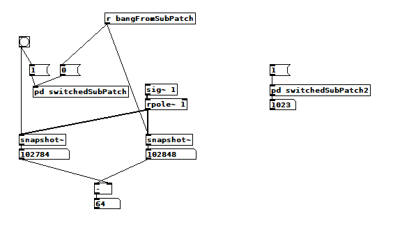
I was hoping to use [bang~] to tell me when a 1024 sample FFT was finished so I could process the results ASAP, but it often bangs after only 64 samples when DSP is first turned on. Here's my test patch after one such run:
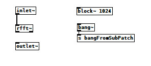
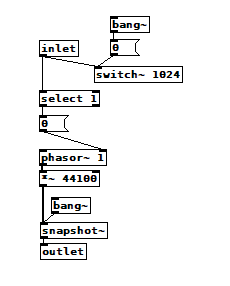
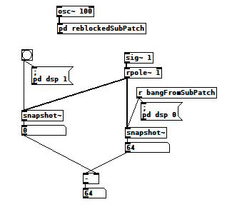 And here's what's inside the reblocked subpatch:
 bang~runsAtTheEndOfEachDSPblock2.pd
After the first run it consistently reports 1024 as expected, but that first run usually shows 64, and only occasionally 1024. I saw 128 once, but haven't been able to reproduce it. I tried connecting the signal inlets and outlets in various ways but it didn't seem to matter. Am I overlooking something?
Update: I get similar results using [switch~]:
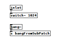
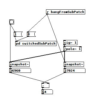 And the switched subpatch:
 switch~ vs bang~.pd
Update #2: I added another test to the switch test and it contradicts the other two tests  When viewed from inside [pd switchedSubPatch2], [bang~] happens at the right time, But if I run the original test immediately afterward, it still shows 64. There must be something about reblocking I don't understand.
 switchedSubPatch2:
 switch~ vs bang~.pd
 posted in technical issues
Best way to create random seed on [loadbang] with vanilla?
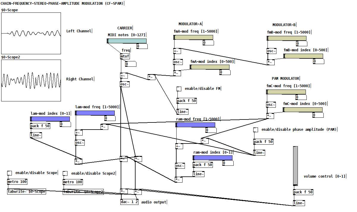
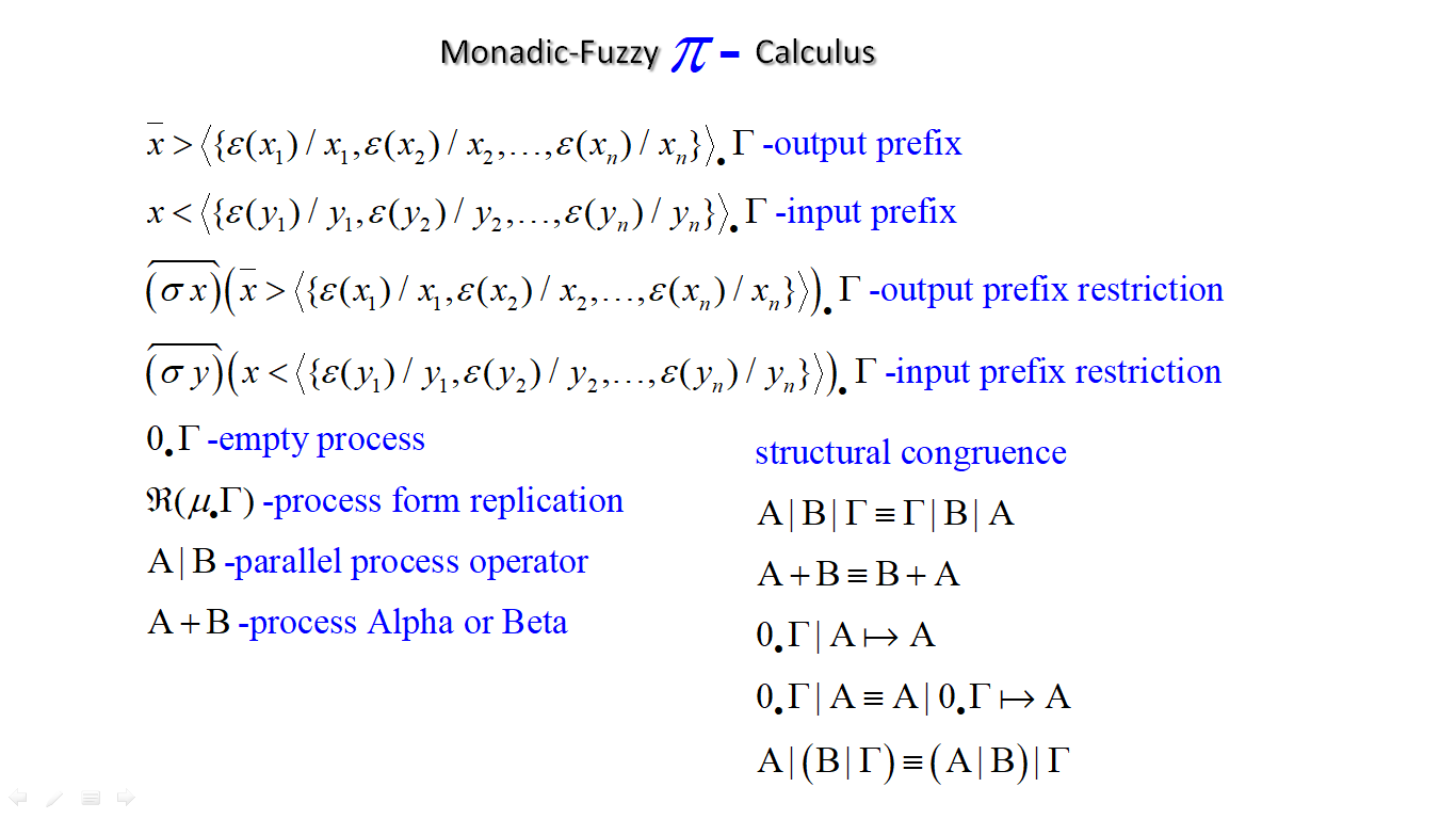
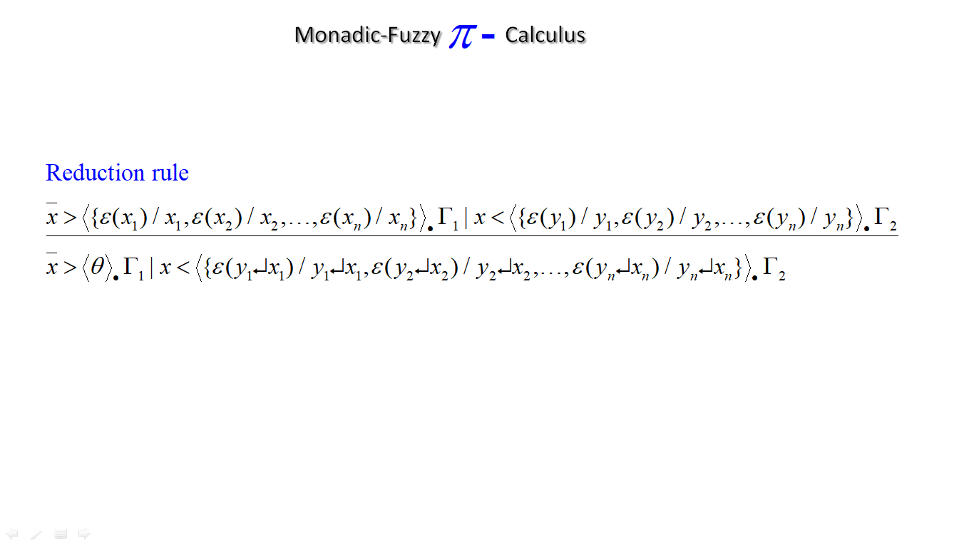
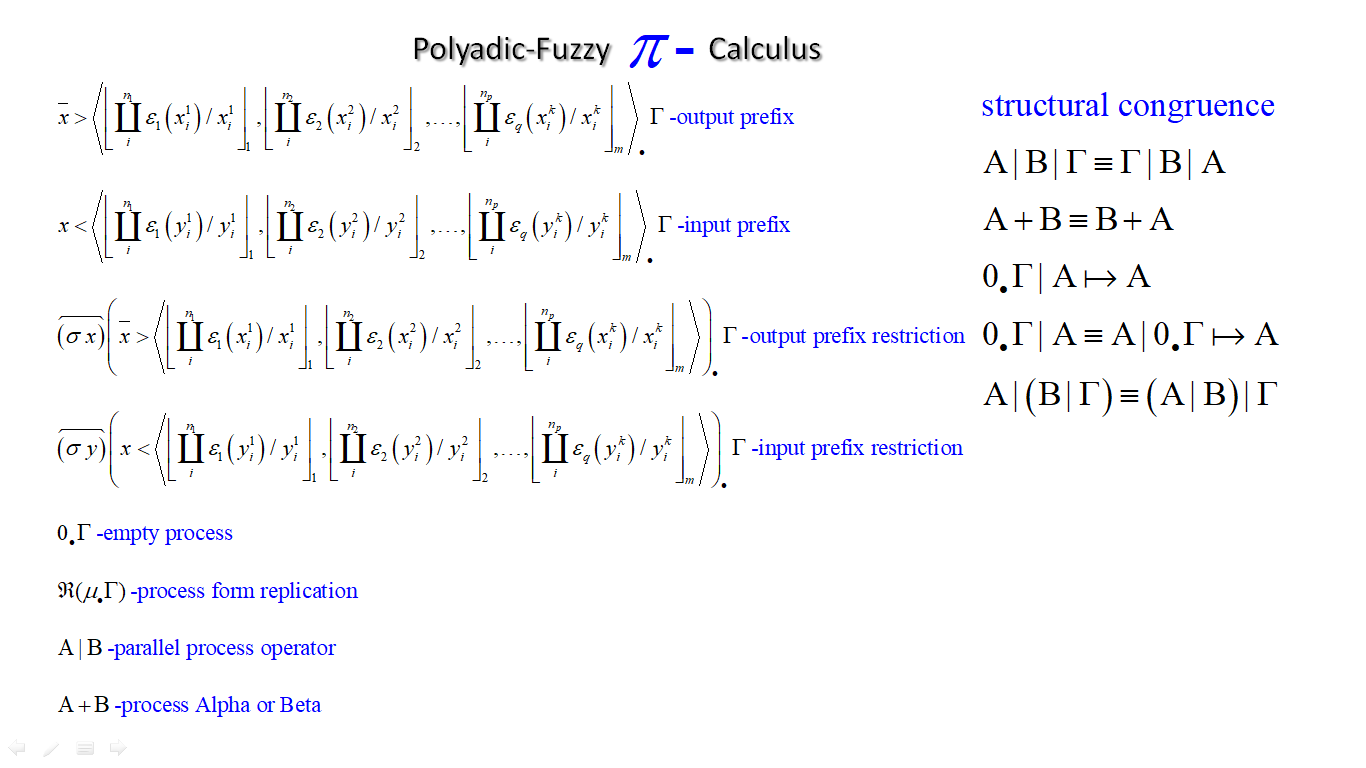
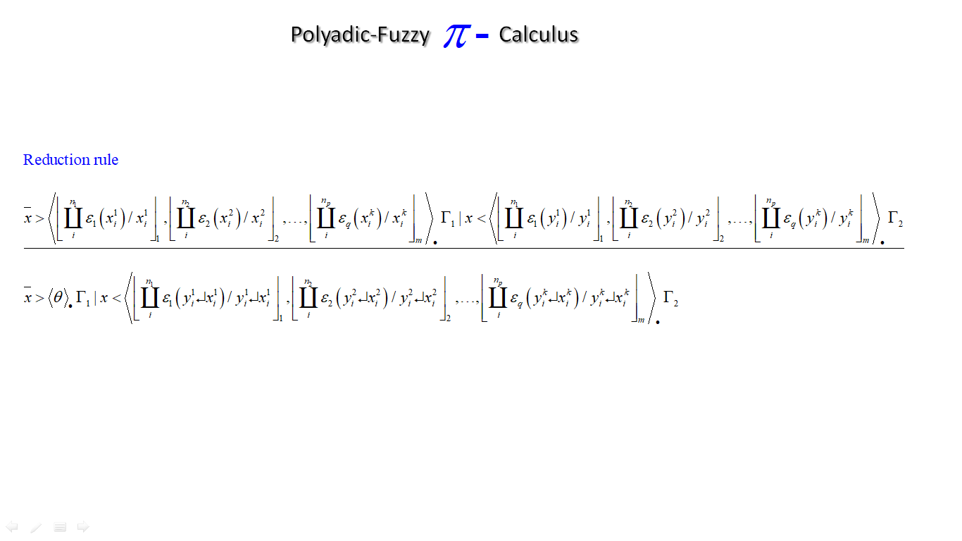
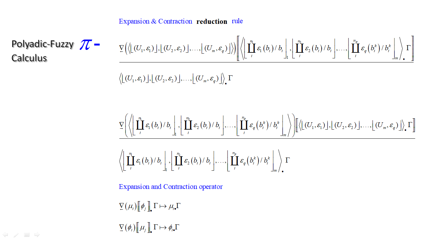
A while a ago i was thinking about a classical system to create random numbers. The idea was to fuse PI-calculus with fuzzy type I in a network system where you can exchange fuzzy type I sets. So the network could output a fuzzy set that could have some specific random properties. I manage to fuse them together but i was still not satisfied by the idea. Now i think that by changing the fuzzy type I to type II together with PI-calculus you can make something like a random number. The monadic-PI-calculus is just for normal fuzzy sets. The Polyadic-PI calculus is a higher order where you can send fuzzy sets of sets over the network.

 posted in technical issues
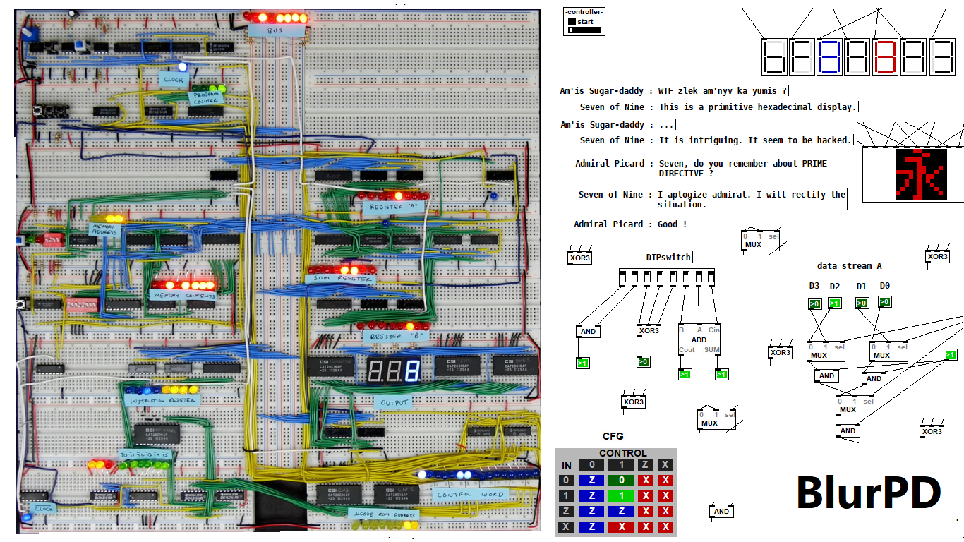
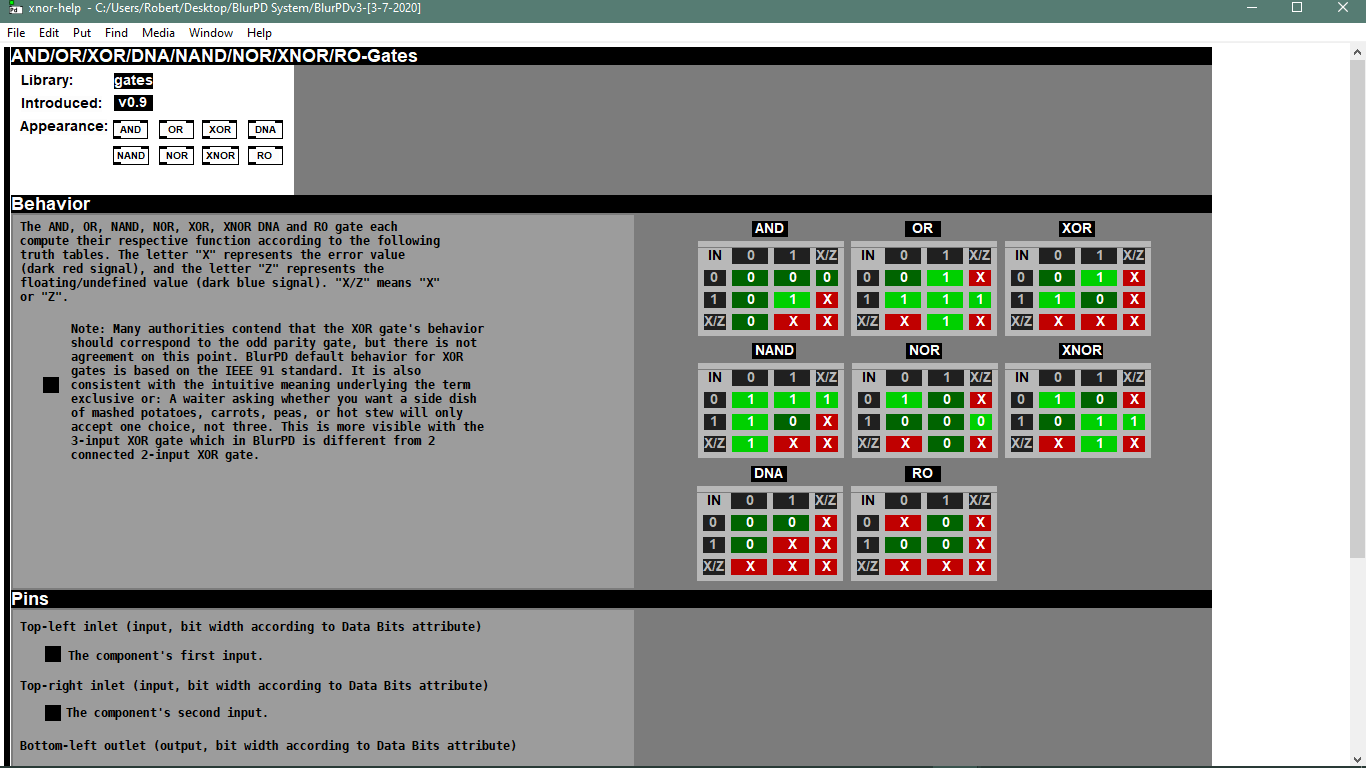
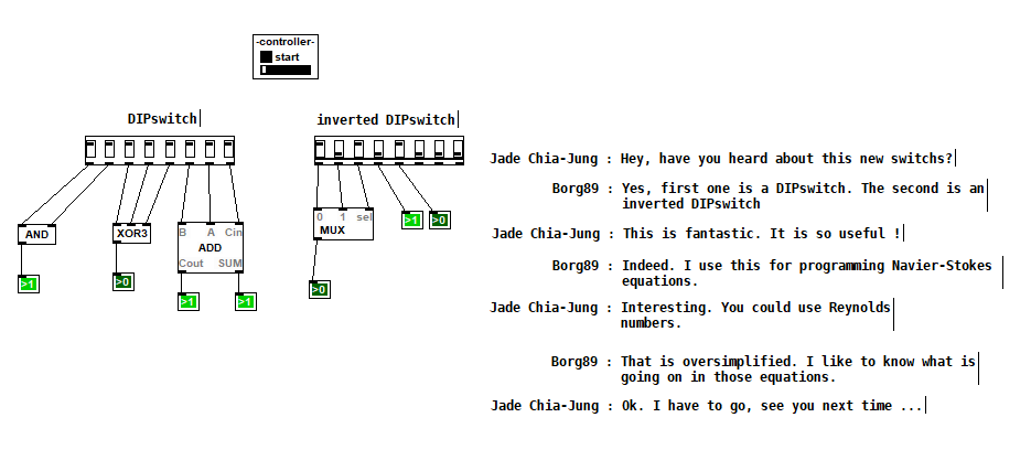
BlurPD - digital logic framework system for Pure Data [v3]
BlurPD is a framework system to extend Pure Data with the ability to make
digital logic circuits while taking advantage of the DSP capabilities of Pure Data. In order to design and simulate interesting circuits, ASIC chips, DSP processors or entire CPU's, all in Pure Data. It is made from jucy fundamental modules (Lego blocks) that when put together turn Pure Data into a madness of bits ...
Bug Fixes & Notes [v3]
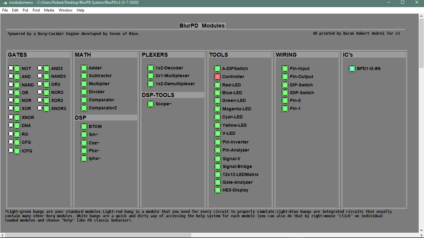
Modules [v3]
- GATES : not,and,nand,or,nor,xor,xnor,cfg,icfg,dna,ro,and3,or3,nand3,nor3,xor3,xnor3
- PLEXERS : 2x1multiplexer,1x2demultiplexer,1x2decoder
- MATH : adder,subtractor,multiplier,divider,comparator,comparator2
- IC : bpd1g8n (integrated 8xNAND gates)
- TOOLS : redled,blueled,greenled,yellowled,magentaled,cyanled,sigv,pininv,gateanalyer
ledmatrix,controller,adipswitch,vled,hexdisplay,sigbridge,pinanalyzer - WIRING : pininput,pinoutput,pin0,pin1,dipswitch,idipswitch
- MODULES : the core library for BlurPD built-in modules
- ICMODULES : the core library for "IC" modules
- DSP : btom,sin~,pha~,ipha~,cos~
- DSPTOOLS : scope~
New Stuff [v3]
- Changes to the Help system. Better GUI and integration [v3]
 patch download
BlurPDv3-[3-7-2020].zip
 BlurPD archive (older versions)
BlurPDv2.9-[3-3-2020].zip
BlurPDv2.8-[3-3-2020].zip
BlurPDv2.7-[3-3-2020].zip
BlurPDv2.6-[3-1-2020].zip
BlurPDv2.5-[2-29-2020].zip
BlurPDv2.4-[2-27-2020].zip
BlurPDv2.3-[2-26-2020].zip
BlurPDv2.2-[2-25-2020].zip
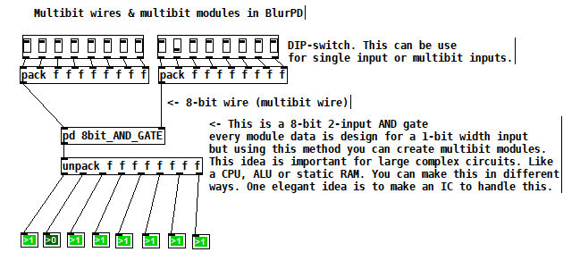
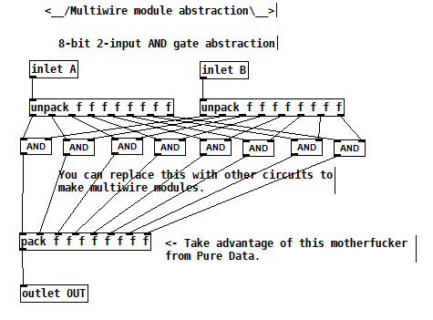
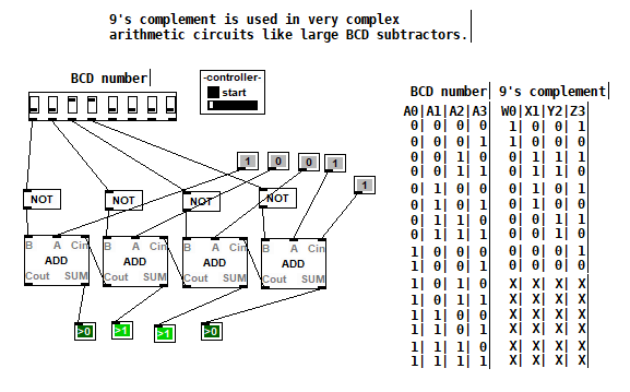
Multibit modules for more complex circuits [v3]
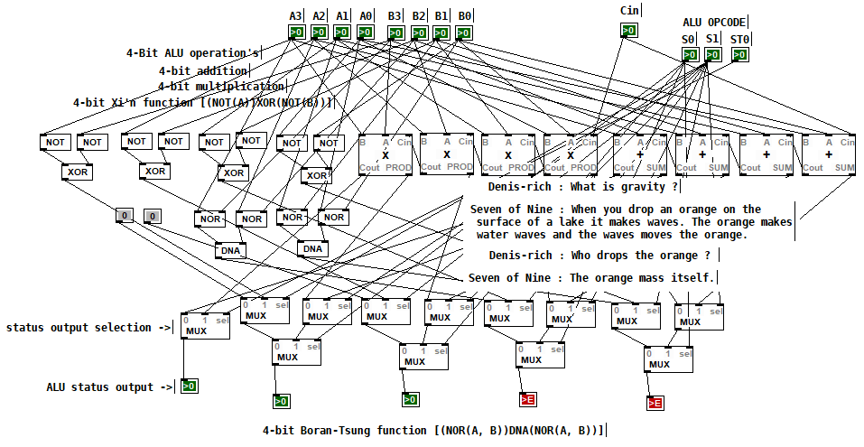
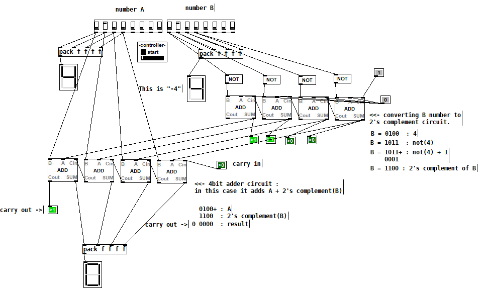
4-bit Boran-Tsung function using a 4-bit ALU (arithmetic logic unit) circuit made with BlurPD [v3]
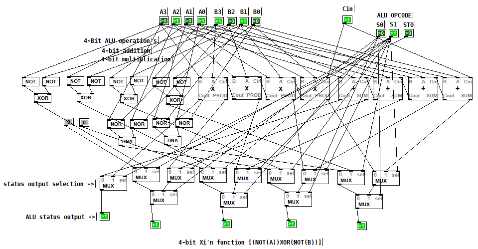
4-bit Xi'n function using a 4-bit ALU circuit made with BlurPD [v3]
Snapshot of the modules system and help system [v3]
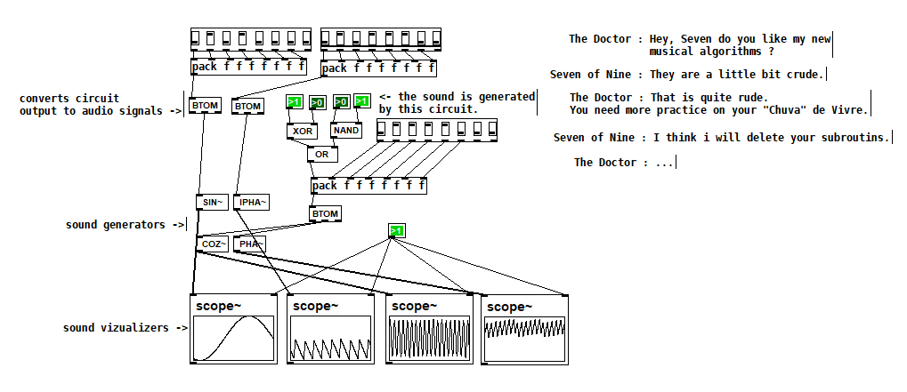
Making generative sounds using new DSP modules [v2.9]
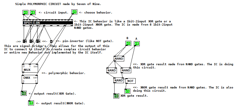
Polymorphic circuit [v2.7]
Application 1 of BlurPD system from [v2.3]
Application 2 of BlurPD system from [v2.3]
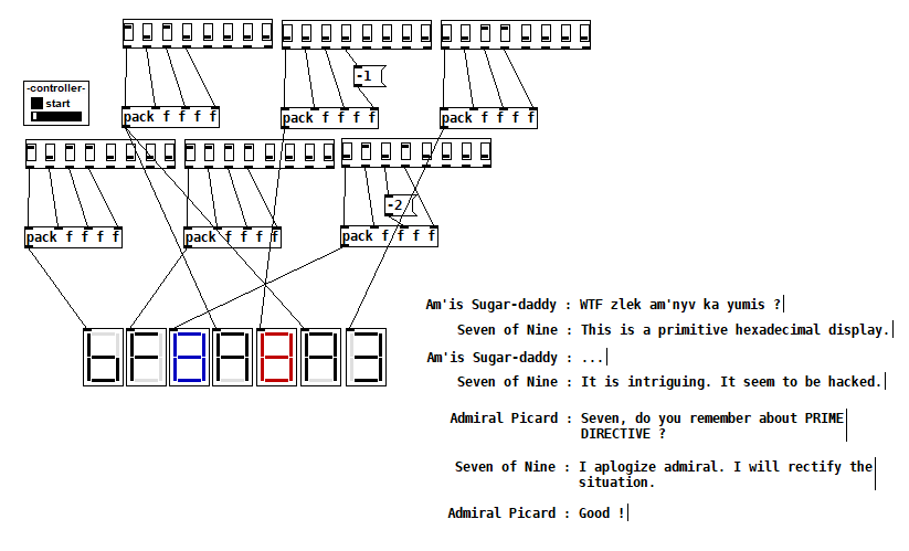
Hexadecimal display [v2.3]
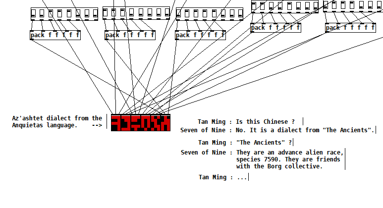
The Ancients [v2.2]
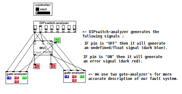
Complex analysis using a DIP-switch analyzer [v2.1]
DIPSwitch from [v2.0]
posted in patch~
Explanation for lop~ object in this patch requested
hi, the impulse response (the name for what happens in the time domain when you feed something an impulse, which has all "frequencies" of sine wave) of a causal low-pass filter generally has a "exponential" ramp characteristic in the time domain. This (of course) corresponds to the frequency response of a lowpass filter. (if you take the discrete fourier transform of the impulse response, it gives the frequency response).
if you lower the "frequency", which generally corresponds to less steepness/longer length of the exponential ramp in the time domain, then the fast changes in the signal will be "integrated" out more
see this thread for further info on using real poles in the time domain like this https://forum.puredata.info/topic/11356/signal-rate-separate-positive-negative-slew/4
also lag~ (which is like lop~ but you can set the coefficient directly) is now in my library, in case you are interested
 posted in technical issues
Build a MIDI controller with the Arduino, Firmata and Pure Data
Time to start contributing some knowledge back to the wonderful world that is the internet; today, a step by step nice and easy tutorial on getting started to building your own MIDI controllers with the arduino.
When researching for my ableton controller project, I didn’t find much out there about using firmata on an arduino to send data to software. The standard approach just seemed to be create the code in the arduino language, upload it to your board and hack one of those MIDI to USB cables as a bodge job way of getting the MIDI out of the arduino.
So why firmata and pure data? Well the whole idea of firmata is that you flash it to your arduino, and it throws out serial about whats going on with the arduino inputs and outputs, then you decide how the software treats the readings coming in and going out.
Theory out the way, lets build some controllers. You’ll need a few things…
HARDWARE:
An arduino and something to wire into it (for this i’ll be using a pot)
A USB cable for your arduino
SOFTWARE:
Arduino – http://arduino.cc/en/Main/Software
Pure Data – http://puredata.info/downloads
Firmata – http://at.or.at/hans/pd/objects.html#pduino
Something to patch your new controller into; like Reason or Ableton Live
- SETTING UP FIRMATA AND PURE DATA
Install Pure Data and create a folder to store all your patches somewhere. Unzip Firmata and add the files ‘arduino.pd’, ‘arduino-test.pd’ and ‘arduino-help.pd’ to your new Pure Data folder. The ‘arduino.pd’ file is the object that we use in PD for opening up communication with your arduino and routing it to PD. Done? Awesome, your software is almost set up.
- FLASHING FIRMATA TO YOUR ARDUINO
Install the latest version of arduino and open it up. Connect your arduino with the USB cable to your laptop (i’m using a macbook for this by the way). In the example patches, open up “Standard Firmata”, select your board (im using an arduino mega), and your serial port (look for tty.usbserial for use with a USB cable). Then compile and hit the upload button and your arduino is now ready to use firmata and communicate with Pure Data!
- WIRING UP A POT
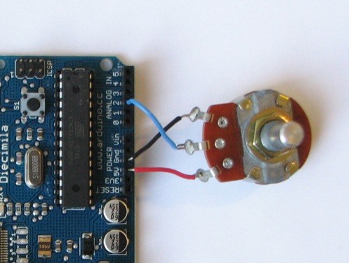
Potentiometers are cool, and theres a great arduino tutorial of how to wire one up here: http://www.arduino.cc/en/Tutorial/Potentiometer
Basically, all you need to know is that there are three pins; your two outer pins govern voltage flow across the pot, meaning one has to be 5V and the other has to be ground. It doesn’t matter which, but your 5v pin is going to be where your pot reads maximum, so convention dictates this should be the right hand pin. The center pin needs to be connected to an analog in on the arduino and will read the value of the pot as it sweeps from ground (0v) to 5v.
All wired up? Plug it into your laptop and open Pure Data, we’re ready to get things talking.
- SETTING UP OUR PATCH
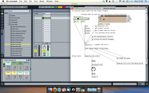
Open the example “arduino-test.pd” Pure Data patch you copied over earlier. It should look like this one…
The test patch has everything we need to open a connection and enable pins. Firstly, lets delete a bunch of stuff and make our window a bit bigger. Hit Command + E to enter edit mode in Pure Data.
Ok a quick explaination; the key component here is the ‘arduino’ object. This is being drawn from the file you copied in earlier, and is what communicated with your arduino. Here we can do everything to control the arduino from opening a connection, to receiving data.
The large grid allows us to set the mode of each pin on the arduino. Remember pins 0 and 1 are reserved for Rx and Tx. I’m using analog pin 4 for this demo, so I’ve set my pin mode for pin 4 to ‘analog’.
Now we can plug our arduino in and get a reading from the potentiometer.
- ARDUINO INTO PURE DATA
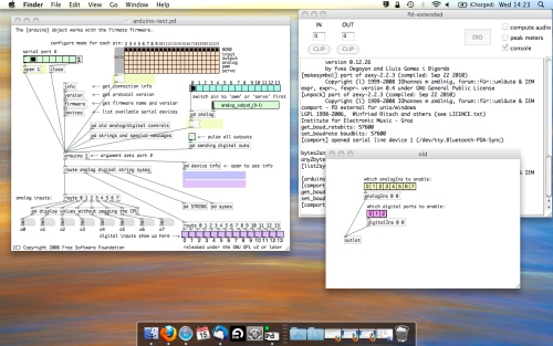
With your arduino plugged in, hit command and E to bring us out of edit mode. In our patch, click on ‘Devices’ above the arduino object and open up the pure data terminal. (That other thing that loads with PD that has all the scary code in)
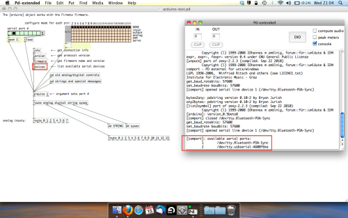
The “Devices” message connected to the arduino object pings your computer to find what devices are connected and on what serial ports. Since we’re using a USB cable to connect our arduino, we’re looking for something with ‘usbserial’ in it, in this case; port 2.
Select the relevent port in the green box at the top (remember the first box is ‘0’, second is ‘1’ and so forth) and hit ‘Open’ to establish a connection. Check the terminal to see if the connection was sucessful.

Now lets check we’re getting something in. Create a number box (Command + 3) and connect it to the relevent pin on the ‘Route analog’ box at the bottom. In this case, pin 4.
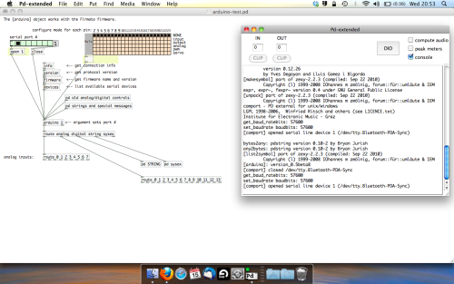
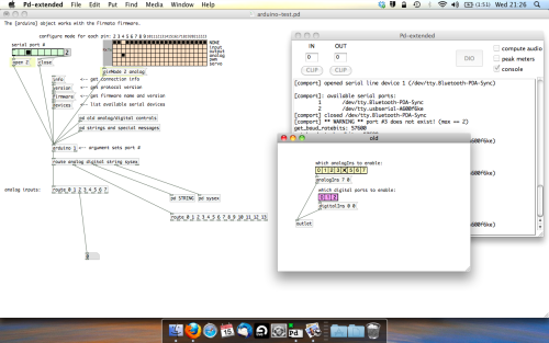
One more thing; if you’re not getting any readings in, you’ll need to click on ‘pd old analog/digital controls’ and enable your pins here too. What I tend to do in my patches is just not include the large grid but make my own ‘old pd’ controls custom to what i’m enabling/disabling to save space.
Here’s what the ‘old analog/digital controls’ subpatch looks like (pin 4 enabled)…
Come out of edit mode and check that you’ve got readings. If so congratulations! If not, troubleshoot, start with making sure your usb connection is opened, make sure all the correct pins are enabled (remember you’re counting from 0 not 1 on most of these buttons in PD, it’s just the way computers work).
- SCALING READINGS TO MIDI
So we’ve got a reading and chances are it’s to 3 decimal places between 0 to 1. No problem, create a new object (Command + 1) and type “autoscale 0 127”. This allows us to scale the input to a min and max value, in this case 0 to 127 of MIDI. Next, lets get things looking nice, create a new object and type “knob”. Connect this AFTER the autoscale object. (the knob is default set to read inputs from 0 to 127. Then create another number to display the scaled MIDI data coming out, and finally a new object and type “ctlout 1”.
It should look something like this…
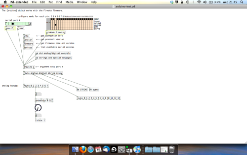
The second box should be outputing values from 0 – 127 now, and the knob giving a visual representation of your potentiometer.
Now lets patch it into ableton…
- PURE DATA TO ABLETON LIVE
Firstly, you’ll need to set up your macs IAC driver if you’ve not done this. Basically you’ll need to go into Audio/MIDI preferences and enable your IAC driver. Then create a new input and output. One for input to DAW and one for output from DAW. Google around for a tutorial on this, its really simple, a 30 second job.
After you’ve set up your IAC driver, go back to PD and go to preferences > MIDI Settings, and connect your IAC driver.
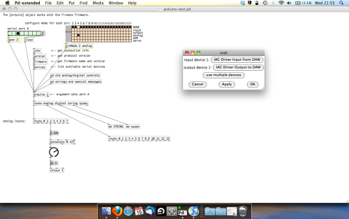
Open ableton and go to its MIDI preferences. Create a device listing for your IAC driver and enable its ins and outs into ableton like so…
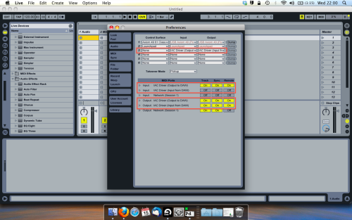
And thats it! Create an instrument and try to assign something! I’ve got it controlling the brightness of a bass sound here.
Shout out for Facu who requested this tutorial. Hopefully it’ll help some of you looking to get into this stuff and start building things but with no idea where to start.
 posted in tutorials
patch with bandwidth limited impulse trains?
here is a description of the waveform generation. now we need a patch for this ... ")
"the main idea behind BLIT is that these analog synth waveforms that we are trying to generate digitally can be thought of as the integral (over tt) of impulse trains.
a sawtooth can be thought of as the integral of the sum of a little bit of DC and an impulse train. a square wave is the integral of impulses of alternating signs. the triangle wave is the integral of the square wave.
so, to create bandlimited waveforms of the above, the impulse trains are bandlimited which means that each impulse δ(t−tn)δ(t−tn) is replaced by a sinc(t−tn)sinc(t−tn) function, which is that impulse bandlimited through a Nyquist brick-wall LPF. that sequence of bandlimited impulses is a BLIT.
then, since integration is a filter with s-plane transfer function of H(s)=1sH(s)=1s and is LTI (Linear, Time-Invariant), integrating the BLITs will introduce no new frequency components. if your BLITs are bandlimited, so are the other waveforms that are derived from filtering the BLITs."
 posted in patch~
Showing the frequency and impulse response in Pure Data
tabwrite~ will work for the impulse response. after that, you have to do a windowed fft on the resulting impulse response in order to get the frequencies present. sorry I don't have a more detailed explanation.
of course, in order to get an impulse response you need to feed your filter a 1 sample impulse and record it to tabwrite~ at the same time
posted in technical issues
Filter "exciter" abstract
why don't you just take a fft of the impulse response? what are you looking for? (an impulse is as wideband as you can get btw, if you feed something like white noise in then you are basically feeding randomly-phased higher frequency components that alias into the fft i think, whereas an impulse is periodic with the period of the fft size though the impulse response might not be so windowing might be needed).
you can generate a 1-sample pulse by using vline~'s delay capability and calculating a sample delay
posted in abstract~
.MOV/.MP4 glitcher
Hi,
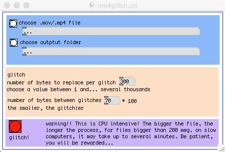
I have built a pd abstraction that glitches .MOV/.MP4 files. This is the result of a long process that involved the study and understanding of the way .MOV files work and their atom structure. Having learned a lot while developping my jpeg and mp3 glitchers, I have been willing to transpose this knowledge to the video realm. To make a long story short, my abstraction locates the mdat atom of the file, reads its length and glitches it in a user-controlable way, while leaving the rest of the filestructure untouched, allowing various degrees of glitchiness with very few unreadable files.
Of course, the bigger the files, he longer the processing time. I have able to glitch a 250 meg MP4 (40 minutes of video) in a bout 1 minute on a macbook pro running under OS 10.10 with the latest stable version of PD extended. On slower computers, processing may take up to 5/6 minutes. Also note that results will vary according to the codec used for compression. I have been able to get good results with H264, but they should all work. As usual with glitch, results will also vary according to the player you use. I personnaly prefer VLC . Some files may appear broken on some players and play just fine on others... Usually, if a file breaks in the process, just tweak the settings a bit to get less glitched file, it should work eventually. This is particulary thrue with small files.
Here's a bunch of stills I took from one processed video:


Here's the pd extend abstraction:
mp4glitcher.pd
It's a graph on parent abstraction, so the idea is to open it like an object in a blank canvas.
And here's the standalone version for mac:
https://1drv.ms/u/s!AjNgShvVLV0XikkivHwWok_tpbYQ
Your comments are welcome!
 posted in abstract~