Oscillator & array - discrepancy between frequency & graph
Hi!
I'm quite new to PD and simply played around a little bit when the following question crossed my mind:
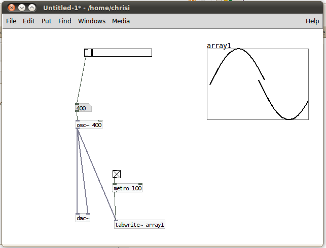
I have an oscillator running at 100Hz and and array which is updated every 100ms. 100Hz means 100 oscillations per second, so one full oscillator swing (from 1 to 1) should last a hundreth of a second = 10ms.
So, if I'm not already wrong at his point, I am supposed to see ten full oscillator circles on the array, no?
What happens with me is that I see one full oscillation at 400Hz. I attached a screenshot of this situation.
What am I getting wrong? ")
Thanks for your help!
 posted in technical issues
Bandlimited oscillators
This is a collection of abstractions that generate bandlimited oscillators. They include:
[bl-saw.mmb~] - bandlimited sawtooth waveform
[bl-pulse.mmb~] - bandlimited pulse wave with PWM
[bl-tri.mmb~] - bandlimited triangle wave
[bl-asymtri.mmb~] - bandlimited asymmetrical triangle wave (sort of...see below)
There is also an object called [bl-init.mmb]. This is the object that initializes all the waveforms and at least one instance MUST be included in order for the others to work.
There are also help patches included.
IMPORTANT!
Before you can use these, you must do the following steps.
1. Open [bl-init.mmb]
2. There is a message box that says [44100(. This is the maximum sampling rate that these will work at (running at lower sampling rates will be fine). If you plan on using higher sampling rates, change this message box and click it. Technically, it will still work at a higher sampling rate, but it won't generate harmonics above the sampling rate in this box.
3. Click the [bang( to fill the wave tables. This patch actually creates a wavetable for EVERY harmonic between 30Hz and the Nyquist frequency. So it will take a few minutes. Be patient! You will get a message in the Pd window when it is done.
4. Save the patch.
Once you do this, [bl-init.mmb] will simply load with the tables already generated, so you don't have to wait every time you instantiate it. I didn't have this already done for you in order to keep the upload small, and so you can see how to adjust it if you need to.
So, I guess I'll go ahead and try to explain how these work. As stated above, every harmonic is generated in [bl-init.mmb] for the oscillators. It doesn't create a table for each set of harmonics however (e.g., there isn't a saw table with two harmonics, a saw table with three harmonics, etc.). Instead, each of these individual tables are tacked on to the end of each other to create one long wave table. So, for each set of 1027 samples in the sawtooth wavetable, there is one cycle with a set amount of harmonics.
When the oscillators read the frequency input, it is divided into the Nyquist frequency to determine how many harmonics are needed. It then uses this (* 1027) as the offset for the table. This is how I got around the problem of table switching at block boundaries. By doing this way, the "switching" is done at audio rate.
There are actually two [tabread4~]s. One has one less harmonic than the other. As the frequency changes it crossfades between these tables. When one table goes completely silent, that's when it "switches." Below 30Hz, they switch to geometrically perfect waveforms.
[bl-saw.mmb~] and [bl-tri.mmb~] just read through the tables. Nothing really interesting about them.
[bl-pulse.mmb~] is actually the difference between to sawtooths. In other words, there are two bandlimited sawtooth oscillators inside of it. Adjusting the pulse width cause the phase of one of the sawtooths to shift. When you subtract this phase-shifted sawtooth from the other, it creates a bandlimited pulse wave...without oversampling! This is the same Phase Offset Modulation method used in Reason's SubTractor.
[bl-asymtri.mmb~] uses the same technique as [bl-pulse.mmb~], except it uses bandlimited parabola waves instead of sawtooths. Adjust the phase offset sets where the top vertex is. This doesn't really generate true triangle or saw waves, though. They still have the parabolic curve in them, so the harmonics seem to come out a little more. It's more of a "reasonable approximation." But, it is bandlimited, and it does sound pretty cool to modulate the shape. I don't have the scaling quite right yet, but I'll get to it later...maybe. ")
I should also mention that these use my [vphasor.mmb~] abstraction, so the phase reset is sample accurate.
I'll eventually set these up to allow frequency and pulse-width arguments, but I'm currently in the process of moving to another country, so it may be a little bit before I get around to it.
Didn't any of that make any sense?
 posted in patch~
Lfo rate and depth
It depends.
osc~ oscillates between -1 and 1 so using it the way you did will not only oscillate the amplitude but also invert the signal.
What you could do is after multiplying it by a factor between 0 and 1 as arif suggests is to add 1 to it. That way it will oscillate between 0 and 2 at the maximum depth and stay centered at 1. That way if your depth is 0 it will stay at it's original amplitude.
It's probably also a good idea to divide the total output by 2 since it might clip at the maximum oscillation.
 posted in technical issues
Hard-syncing phasors
Hello,
I'm trying to make something that sounds like C64 SID chip. One particular property of that chip is that, it is possible to hard-sync two oscillators, so that the slave oscillators phase is reset to zero every time master oscillators phase returns to zero. I couldn't find a a way to implement this in pd.
Trying to capture the zero crossings on the master oscillator seems to be a dead end, because i'll have to turn it into a control signal somewhere to connect it to the phase input on slave phasor. And control signals are much too slow to catch every zero crossing.
Any ideas?
 posted in technical issues
\[zerox~\]
If you plan on using [xerox~] to phase sync two oscillators, it probably won't cut it. Generally, you want those things to be sample accurate. [xerox~] will give you a click corresponding to zero crossings out its right outlet, but, as far as I know at least, Pd's oscillators can't really use that for phase syncing ([xerox~] is actually based on a Max object, yet strangely Max's oscillators can't use it either). It would require a conversion to message rate to reset the phase, which kills sample accuracy, not to mention the fact that the phase input of [phasor~] quantizes to block boundaries (default 64 samples in Pd), which also kills sample accuracy.
However, if you know the ratio between your two oscillators, phase syncing can be achieved using a master [phasor~] to run both oscillators. Use the master sync frequency to drive the [phasor~], then multiply the output of the [phasor~] by the ratio between the synced (slave) oscillator and the master one. In other words, it should be multiplied by:
slave frequency / master frequency
Then, you just [wrap~] the signal and viola, you have a new synced phasor signal to drive the slave oscillator. The attached patch should hopefully clarify.
posted in technical issues
Noise-\>osc
ha ha, it's not very scientific. but anyway...
[noise~] outputs a random value between -1 and 1 every sample.
we then multiply the output of [noise~] by a number between 2000 and 20000
this means that going into the frequency control of the [osc~] object will be a signal between -2000 and 2000 at the lowest setting, and -20000 and 20000 at the highest setting.
sending negative frequencies into [osc~] is just the same as positive ones, but the oscillator wave flows in the opposite direction.
so, every sample, we are changing the frequency of the [osc~] oscillator. if we only oscillate at frequencies between -2000 and 2000, then the maximum frequency output will be 2000hz. however if we ramp it right up to 20000, then the oscillator will oscillate at higher frequencies.
it still sounds like noise though, because the frequency of [osc~] is changing so rapidly that there is barely any periodic content in the output waveform.
 posted in patch~
Fatosc~
hello all.
I'm a total newcomer here, and I have more or less 2 days working experience with Pd
so please bear with me for the "bad coding" or naivety or whatever. anyway, this is my first Pd patch, and I thought it deserves to be shared.
it is a morphing oscillator with controllable fatness, thus called "fatosc~". it has 2 inlets (frequency and fatness) and one outlet (the noise!).
the "fatosc~demo" patch features an oscilloscope and can be eventually played via MIDI. (no envelope or fancy stuff, monophonic and note on/off sensing seems to be a bit flakey).
I originally coded the oscillator for a completely different project of mine, but wanted to do some quick soundcheck with a realtime system, and Pd fitted just perfectly.
the original C code looks like this:
if(phase > 0.75) {
    output = -1.0 + pow((phase-0.75)*4.0, fatness);
} else if(phase > 0.50) {
    output = -1.0 + pow(1.0-(phase-0.50)*4.0, fatness);
} else if(t > 0.25) {
    output = 1.0 - pow((phase-0.25)*4.0, fatness);
} else {
    output = 1.0 - pow(1.0-phase*4.0, fatness);
}
I had a hardtime figuring out a Pd equivalent for if/else. and I'm still not sure I got it right
anyway: with fatness=1 the oscillator generates a triangle wave. with fatness=PI, it generates a sine wave (don't know if it's a mathematically pure sine, but it looks pretty similar). going up with the fatness, it approximates a square wave.
on the other hand, with fatness < 1 it generates a nice looking curved triangle waveform, which I've called "jawtooth". I was really thinking "shark tooth", but my fingers are faster than thought
with very small fatness values, it "degenerates" to almost silence.
should be interesting to do some FM or other modulation with it. that's what I'm going to try next.
hope you find it useful and/or entertaining.
PS. of course, the algorithm is "pat.pend.", so if you're going to use it in a commercial product, my horde of lawyers will knock at your door and haunt you in your dreams.
ok, just jocking, feel free to do whatever you like with it.
critics welcome!
cheers,
Aldo
 posted in patch~
Best way to bitcrush a triangle wave?
@hardoff said:
my quick answer,
[tri~] [phasor~]
| /
[samphold~]
Thats almost it Hardoff, the phasor must be synchronous with the triangle, so best trick is to do this
[phasor~ x]
| \
| \
| [*~ 8] <- vary quantisation here
| [wrap~]
| |
[samphold~]
Then derive the triangle from the quantised phasor using the usual methods
 posted in technical issues
How do you timestretch?
Even easier. Forgive me, I'm new to Pd so this will be in Reaktor speak.
You can do this with basic granular synthesis. Do to it Homebrew style you need three things. You need two ramp oscillators (phasors?) and a clock generator. The main ramp sets the play position in samples, but ONLY when the clock generator bangs. The other ramp oscillator (phasor?) determins the pitch, so this is basically what you have now, just a basic table read. When the clock gen bangs this pitch osc is reset.
The speed of the clock generator is in milliseconds, this is the grain time.
BOTH the oscilators are added together, this sum is your new play position in your table!
It works pretty well, I've implemented it in reaktor. Hope this helps. Any questions, email me.
 posted in patch~