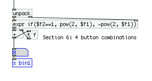
Problem with the binary design.....I im using th binary Base -2 column to represent the four toggles Im using to count... graph to illustrate. currently im using "combination that equals the decimal Base - 10 no. 1 or 2 for oct+ and oct - , on a chromatic keyboard. I then need to use "3" to trigger an LFO which is a combination, of the combination that make 1 & 2. however it means that when i want to get to the LFO trigger i jumps through the jobs of 1 & 2 change the octave im on when i need a bit of tremelo... this area of the patch is receiving the 1 and 2 to change the octave
  ....
....
-
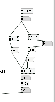
Binary Counter
-
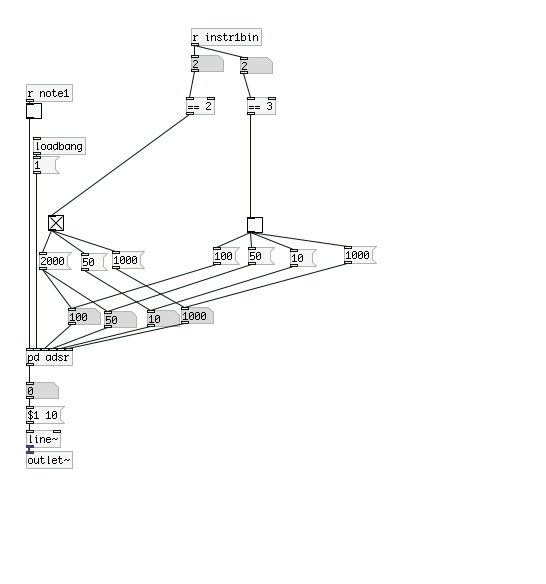
im using the binery counter to select different values on the ADSR but when i select 2 for some reason it doesnt change the values in the number box after 3?

-
You should use [sel 2 3] in place of [== 2] and [== 3] and replace the toggles with gui bangs to visualise the result.
Logic operators and gui objects like toggle will output bangs for both states.
And the order the wires were connected determines the order of operation.
Use [trigger] if the order is important [trigger] fires right to left eg. [t b f] if a float is sent to the inlet, that float is passed to the right outlet and then a bang is sent to the left outlet.

