Arduino->Pd with Open Sound Control
@jameslo Thanks a lot!
I can send messages locally between Pd, Processing and Unity. But not Arduino.
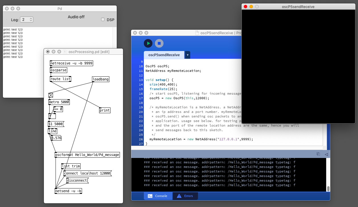
oscProcessing.pd
oscUnity.pd
oscP5sendReceive.pde
These works but I can still not for example replace Processing with Arduino.
@jameslo said in [Arduino->Pd with Open Sound Control] do you need bidirectional messaging? What data are you passing (if any)? What Arduino library would you prefer to use (I see there are more now than when I started)? is it over WiFi or ethernet or something else?
-bidirectional is good. Type of data, analog float, and digital. I have no preference for what library I use. I just want to make it work locally on a single computer.
I would like to use the Arduino as a controller for Pd through OSC.
For example, 5 analog ins on the Arduino that I after som treatment (smoothing and more) send locally to Pd, with custom osc addresses: /myArduino/analog-0
 posted in I/O hardware diy
[comport] lost connection retry failing
Hi, I'm working on a Pd patch that connects to a few sensors via SLIP serial OSC. The serial implementation is based on this example : https://github.com/CNMAT/OSC/tree/master/Applications/PD
Everything works wonders and is really stable; however I run into an issue when a serial connection is lost, for instance when we I reset one of the sensors for calibration purposes. The patch is running headless on a RPI4 and the idea is "never" have to ssh in order to reload the Pd as this is running on a permanent sound installation.
I have created bind USB address on linux using the deviceID and vendorID of my sensors therefore naming on /dev/ is static (/dev/sensor_1, /dev/sensor_2, etc ...). I have also specified a large amount of retries on the [comport] object to allow the sensor to show up /dev/. But when I unplug one of the sensor, I can see [comport] loosing the connection and listing the retries:
error: [comport]: lost connection to port 9999 (/dev/sensor_1), retrying...
errors: retrying 45
I have also made sure that /dev/sensor_1 is back up on /dev/ while I can see [comport] endlessly trying to connect to it.
I think I'm running out of ideas here ... and would be grateful if someone could give me some pointers on how to either fix this issue; or finding another way around in order to ensure a dropped device will reconnect to my patch.
Thank you
 posted in technical issues
Having lots of switches into Pd
Here is the working Arduino code, (which is basically a straight copy from "project 8", but I wrote it while reading the tutorial)
// setup for 6 analog in och 12 digital in (pullup to be added).
//intended as experimental template. use pd patch
//made with tutorial Arduino for Pd'ers, project 8

byte myArray[25];

void setup()
{
  for(int i = 2; i < 14; i++)
  pinMode(i, INPUT);
  Serial.begin(9600);
}

void loop()
{
  myArray[0] = 0xc0;
  int index = 1;

  for(int i = 0; i < 6; i++){
    unsigned int knob = analogRead (i);
    myArray[index++] = knob & 0x007f;
    myArray[index++] = knob >> 7;
  }
  for(int i = 2; i < 14; i++)
  myArray[index++] = digitalRead(i);

  Serial.write(myArray, 25);
}
Then I tried to incorporate project 1 (blink):
// set a variable to hold the ledddddddz pin number
int led = 13;

void setup()
{
//  st pin 13 as output, to light up the LED
// whenever it is told so from Pd
pinMode(led, OUTPUT);
// start the serial communication o the Arduino
// and Pd can communicate with each other
Serial.begin(9600);
}

void loop()
{
 while(Serial.available()){
  byte ledState = Serial.read() - '0';
  digitalWrite(led, ledState);
 }
}
but when I tried to edit "blink" to work with several outputs and merge this in the project 8 code, I decided that I do not have enough understanding of the arduino code to pull it through. What is needed is, I think, another "for()" combined with digitalWrite() inside void loop()
Note: My plan now is to (still) use several Arduinos but with your code and abstractions (instead of the Pdunio). I will wait with the matrix switch setup since I have to take this in steps in order to have control of it.
This means that I am up and running, unless I want to use digital input and output from the same Arduino at the same time. I figure it would be great to have that sorted out beforehand so it works when I need it.
Thanks a lot.
posted in I/O hardware diy
Android processing and Purr data communication
Hi!
I have a new problem,
Everthing is working but not when I want to use the accelerometer of the phone, that's really weird.
Processing is receiving but not PD
Processing code:
import android.content.Context;
import android.hardware.Sensor;
import android.hardware.SensorManager;
import android.hardware.SensorEvent;
import android.hardware.SensorEventListener;
import oscP5.;
import netP5.;
import controlP5.*;
ControlP5 controlP5;
OscP5 oscP5;
NetAddress myRemoteLocation;
Context context;
SensorManager manager;
Sensor sensor;
AccelerometerListener listener;
float ax, ay, az;
void setup() {
fullScreen();
frameRate(25);
// create a new instance of oscP5.
// 12000 is the port number you are listening for incoming osc messages.
oscP5 = new OscP5(this, 12000);
myRemoteLocation = new NetAddress("192.168.137.1", 12011);
controlP5 = new ControlP5(this);
context = getActivity();
manager = (SensorManager)context.getSystemService(Context.SENSOR_SERVICE);
sensor = manager.getDefaultSensor(Sensor.TYPE_ACCELEROMETER);
listener = new AccelerometerListener();
manager.registerListener(listener, sensor, SensorManager.SENSOR_DELAY_GAME);
textFont(createFont("SansSerif", 30 * displayDensity));
}
void draw() {
background(0);
text("X: " + ax + "\nY: " + ay + "\nZ: " + az, 0, 0, width, height);
}
class AccelerometerListener implements SensorEventListener {
public void onSensorChanged(SensorEvent event) {
ax = event.values[0];
ay = event.values[1];
az = event.values[2];
print(ax);
print(ay);
print(az);
}
public void onAccuracyChanged(Sensor sensor, int accuracy) {
}
}
void mousePressed() {
/* in the following different ways of creating osc messages are shown by example */
//OscMessage myMessage = new OscMessage(int(knobValue));
//myMessage.add();
OscMessage myMessage = new OscMessage("/test");
myMessage.add(ax);
myMessage.add(ay);
myMessage.add(az);
/* send the message */
oscP5.send(myMessage, myRemoteLocation);
}
PD code:
[import mr peach] -----> [udpreceive 127.0.0.1 12000]--------->[unpackOSC]------->[routeOSC /test]---->[number]
I've already try like that too :
[import mr peach] -----> [udpreceive 127.0.0.1 12000]--------->[unpackOSC]------->[routeOSC /test]----> [unpack f f f]-------->[number]
Thanks in advance
 posted in technical issues
Playing sound files with a volume according to velocity.
Hello!
I am using a raspberry pi and puredata to make a drum kit. I have sounds which are read through soundfiler and I activate them by using Gpio inputs via wiringPi.
Now I am trying to use an arduino to read analog values from the peizoelectric sensors, map them to midi value, and send them via a usb midi cable to puredata.
That is done, but how will I be able to play back sounds with a volume that is equal to the velocity in the midi packet?
Example- If I strike the sensor hard, the arduino sends 127 as midi value and puredata should play back a sound at full volume, and if I strike the sensor softly, the sound should play back at less volume.
Note that I am thinking of having velocity sensitivity, and not aftertouch (would be cool to add later on).
Regards,
Shaurya
 posted in technical issues
pduino for Vanilla or how to control arduino outputs from PD
[arduino] is the Pduino abstraction that communicates with Arduino via Firmata, and I think it's vanilla. Any way, if all you want is to control Arduino pins from Pd, you just need to send the correct bytes to Arduino through [comport].
I've written a tutorial on the communication between Pd and Arduino which you can find here, under "Tutorials", it's called "Arduino for Pd'ers".
After I wrote the tutorial I also wrote some abstractions to facilitate this communication, which are not used in the tutorial. You can get them here. Though, these are meant to receive data from the Arduino, not send. Sending data is covered in the tutorial.
 posted in technical issues
PIR Sensor Pduino
This is more of a hardware problem so this might not be the right forum but here goes: I hooked up a PIR sensor to a Pduino patch (Pure data for Arduino) and my sensor is only emitting 3V at regular intervals of 4310 ms. It doesn't seem to react to movement whatsoever. When I change the delay time it seems to do the same but at longer intervals.
Pduino is reacting well to Arduino so no problems there, it’s just the sensor itself tata is not working…
Does someone have any ideas??
 posted in I/O hardware diy
Build a MIDI controller with the Arduino, Firmata and Pure Data
Time to start contributing some knowledge back to the wonderful world that is the internet; today, a step by step nice and easy tutorial on getting started to building your own MIDI controllers with the arduino.
When researching for my ableton controller project, I didn’t find much out there about using firmata on an arduino to send data to software. The standard approach just seemed to be create the code in the arduino language, upload it to your board and hack one of those MIDI to USB cables as a bodge job way of getting the MIDI out of the arduino.
So why firmata and pure data? Well the whole idea of firmata is that you flash it to your arduino, and it throws out serial about whats going on with the arduino inputs and outputs, then you decide how the software treats the readings coming in and going out.
Theory out the way, lets build some controllers. You’ll need a few things…
HARDWARE:
An arduino and something to wire into it (for this i’ll be using a pot)
A USB cable for your arduino
SOFTWARE:
Arduino – http://arduino.cc/en/Main/Software
Pure Data – http://puredata.info/downloads
Firmata – http://at.or.at/hans/pd/objects.html#pduino
Something to patch your new controller into; like Reason or Ableton Live
- SETTING UP FIRMATA AND PURE DATA
Install Pure Data and create a folder to store all your patches somewhere. Unzip Firmata and add the files ‘arduino.pd’, ‘arduino-test.pd’ and ‘arduino-help.pd’ to your new Pure Data folder. The ‘arduino.pd’ file is the object that we use in PD for opening up communication with your arduino and routing it to PD. Done? Awesome, your software is almost set up.
- FLASHING FIRMATA TO YOUR ARDUINO
Install the latest version of arduino and open it up. Connect your arduino with the USB cable to your laptop (i’m using a macbook for this by the way). In the example patches, open up “Standard Firmata”, select your board (im using an arduino mega), and your serial port (look for tty.usbserial for use with a USB cable). Then compile and hit the upload button and your arduino is now ready to use firmata and communicate with Pure Data!
- WIRING UP A POT
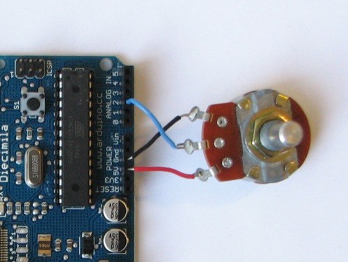
Potentiometers are cool, and theres a great arduino tutorial of how to wire one up here: http://www.arduino.cc/en/Tutorial/Potentiometer
Basically, all you need to know is that there are three pins; your two outer pins govern voltage flow across the pot, meaning one has to be 5V and the other has to be ground. It doesn’t matter which, but your 5v pin is going to be where your pot reads maximum, so convention dictates this should be the right hand pin. The center pin needs to be connected to an analog in on the arduino and will read the value of the pot as it sweeps from ground (0v) to 5v.
All wired up? Plug it into your laptop and open Pure Data, we’re ready to get things talking.
- SETTING UP OUR PATCH
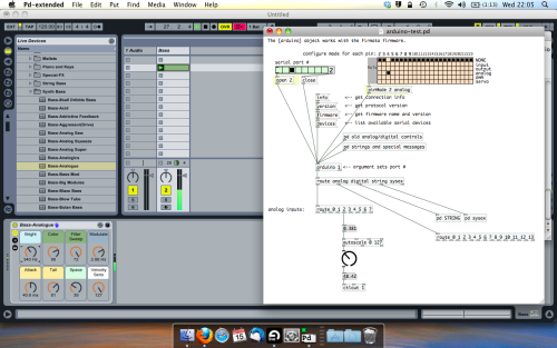
Open the example “arduino-test.pd” Pure Data patch you copied over earlier. It should look like this one…
The test patch has everything we need to open a connection and enable pins. Firstly, lets delete a bunch of stuff and make our window a bit bigger. Hit Command + E to enter edit mode in Pure Data.
Ok a quick explaination; the key component here is the ‘arduino’ object. This is being drawn from the file you copied in earlier, and is what communicated with your arduino. Here we can do everything to control the arduino from opening a connection, to receiving data.
The large grid allows us to set the mode of each pin on the arduino. Remember pins 0 and 1 are reserved for Rx and Tx. I’m using analog pin 4 for this demo, so I’ve set my pin mode for pin 4 to ‘analog’.
Now we can plug our arduino in and get a reading from the potentiometer.
- ARDUINO INTO PURE DATA
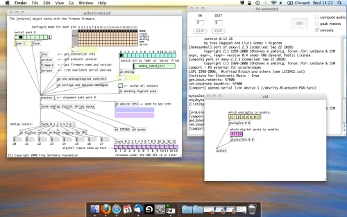
With your arduino plugged in, hit command and E to bring us out of edit mode. In our patch, click on ‘Devices’ above the arduino object and open up the pure data terminal. (That other thing that loads with PD that has all the scary code in)
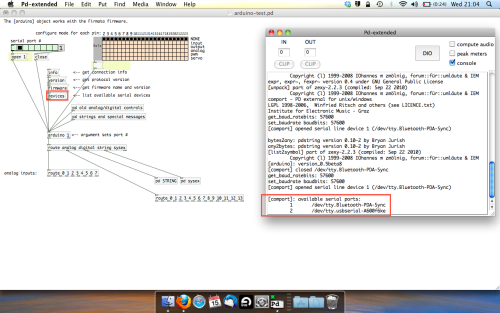
The “Devices” message connected to the arduino object pings your computer to find what devices are connected and on what serial ports. Since we’re using a USB cable to connect our arduino, we’re looking for something with ‘usbserial’ in it, in this case; port 2.
Select the relevent port in the green box at the top (remember the first box is ‘0’, second is ‘1’ and so forth) and hit ‘Open’ to establish a connection. Check the terminal to see if the connection was sucessful.

Now lets check we’re getting something in. Create a number box (Command + 3) and connect it to the relevent pin on the ‘Route analog’ box at the bottom. In this case, pin 4.
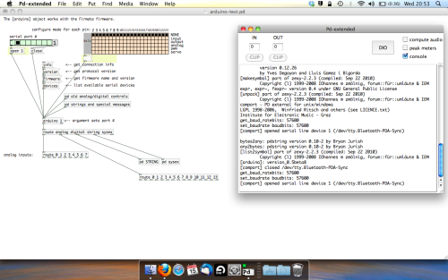
One more thing; if you’re not getting any readings in, you’ll need to click on ‘pd old analog/digital controls’ and enable your pins here too. What I tend to do in my patches is just not include the large grid but make my own ‘old pd’ controls custom to what i’m enabling/disabling to save space.
Here’s what the ‘old analog/digital controls’ subpatch looks like (pin 4 enabled)…
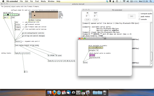
Come out of edit mode and check that you’ve got readings. If so congratulations! If not, troubleshoot, start with making sure your usb connection is opened, make sure all the correct pins are enabled (remember you’re counting from 0 not 1 on most of these buttons in PD, it’s just the way computers work).
- SCALING READINGS TO MIDI
So we’ve got a reading and chances are it’s to 3 decimal places between 0 to 1. No problem, create a new object (Command + 1) and type “autoscale 0 127”. This allows us to scale the input to a min and max value, in this case 0 to 127 of MIDI. Next, lets get things looking nice, create a new object and type “knob”. Connect this AFTER the autoscale object. (the knob is default set to read inputs from 0 to 127. Then create another number to display the scaled MIDI data coming out, and finally a new object and type “ctlout 1”.
It should look something like this…
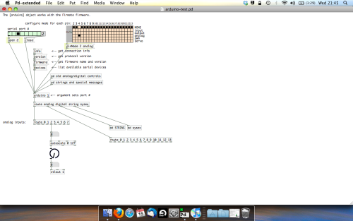
The second box should be outputing values from 0 – 127 now, and the knob giving a visual representation of your potentiometer.
Now lets patch it into ableton…
- PURE DATA TO ABLETON LIVE
Firstly, you’ll need to set up your macs IAC driver if you’ve not done this. Basically you’ll need to go into Audio/MIDI preferences and enable your IAC driver. Then create a new input and output. One for input to DAW and one for output from DAW. Google around for a tutorial on this, its really simple, a 30 second job.
After you’ve set up your IAC driver, go back to PD and go to preferences > MIDI Settings, and connect your IAC driver.
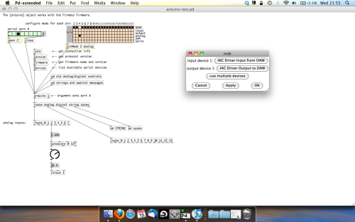
Open ableton and go to its MIDI preferences. Create a device listing for your IAC driver and enable its ins and outs into ableton like so…
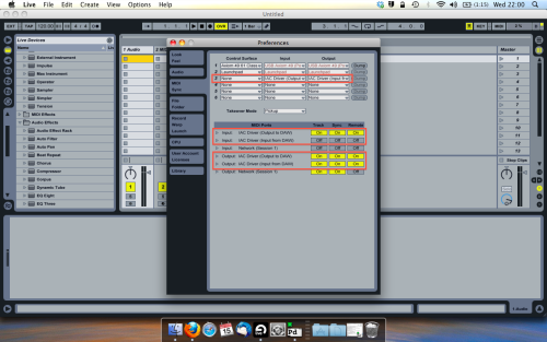
And thats it! Create an instrument and try to assign something! I’ve got it controlling the brightness of a bass sound here.
Shout out for Facu who requested this tutorial. Hopefully it’ll help some of you looking to get into this stuff and start building things but with no idea where to start.
 posted in tutorials
HC-SR04 Ultrasonic Sensor with Pd (How long does a bang last?)
Hi,
I'm trying to use an HC-SR04 Ultrasonic sensor through arduino with Pure Data using Pduino and Standard Firmata. Pduino works perfectly and I am able to get data from many other sensors. This particular sensor is slightly different because it needs me to send a pulse of length 30 micro seconds at a time interval of more than 60 milliseconds to the trigger pin of the sensor, which triggers the ultrasonic waves from the transmitter. The receiver of the sensor measures the ultrasonic waves as they bounce back after reflecting from an external object to measure the distance.
My problem is that I am trying to figure out how to give a 30 microsecond pulse as an output from Pd, which leads me to ask, how long does a 'Bang' last? Is there another way to set up a pulsing mechanism where I can control the time interval of the pulse? Something like the pulseIn() function in Arduino IDE?
 posted in I/O hardware diy
Pduino + Arduino Output to Pins
Unfortunately, snapshot~ doesn't seem to send data at a rate which enables clean signaling of arduino pins. When it comes to audio anything, I find that outputting signal is necessary, as outputting control values just cannot keep up with audio. If you are looking to make a square wave generator that is controllable from puredata, the best way that I have found to do this is by using a combination of arduino, a DAC chip and an op-amp chip. Also, you'll want to use at least a 12 bit DAC, such as mcp4921 or mcp4725, as 8 bit DAC lacks the ability to tune the output fine enough to stay in tune with standard tuning. For opamp choices, you can pretty much take your pick. They all do pretty much the same thing, though you will find that every opamp has it's own unique sound quality. I really love the gritty sound of the CA313. A very good and popular sound for opamp VCO is the tl072 or tl075. There are tons of schematics out there for how to configure a square wave vco with opamps. You would just modify the components to fit the output of your DAC.
Next, you would send your controller values from PD to the arduino and have some code in the ar'dweener to handle communicating with the DAC. You can then add all sorts of fun stuff to your board like digipots, opamp buffers, VCAs and so on to make envelopes, LFOs etc.
If you don't want to track down additional chips (usually ordered from china being the only way to find them, cheap though they tend to be,) but want to have square waves being output directly from the arduino, then you would still be better off having pd send control values to the arduino and then let the arduino handle the signal generation to it's pins. For this purpose, you may want to look at the tone library or the mozzi library. Teensy boards have some expanded audio capabilities as well, but teensy boards are a bit expensive for my taste, as you can get a freakin raspberry pi with a full linux operating system on it for a fraction of what it costs. Still, teensies are great and extremely handy for these types of applications if you dont mind dropping some extra money. I try to build everything to work on cheap arduino clones just for financial and practicality sake.
I have code and patches that I have written to control these types of circuits for many DACs and digipots with SPI and I2C protocalls... let me know if you'd like to check them out for some guidance.
 posted in technical issues