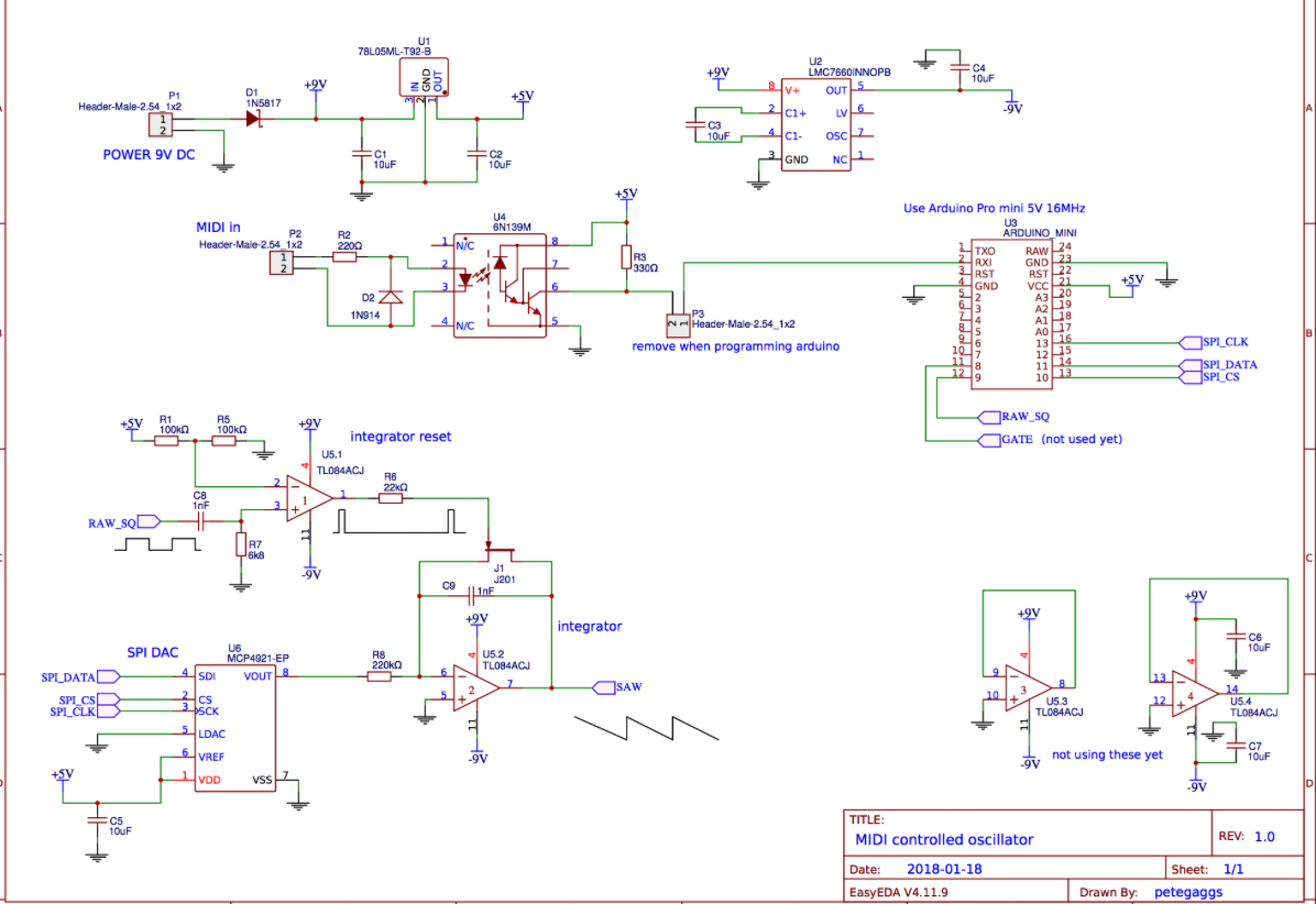
@Beginz Hello, and welcome to the wrong forum.......
But you will get help here anyway with some things electronic......
I hope you are using Pure Data. If you are not then you should look into it...... it is easy to learn, and well worth the effort...!
I don't think you need to worry about your circuit.
It is a standard midi opto-isolaton circuit........ still meeting the revised midi spec 2014.
https://www.midi.org/specifications/item/midi-din-electrical-specification
The led must have some resistance as well, or it could not emit any light, but it is probably around 13R..... so pretty insignificant compared to the 220R.
But with any luck you will not be sending DC. The data stream duty cycle will be 50% or much less "on" probably, and the 6N139 has some noise rejection circuitry pre the led...... so......?
BUT, much more importantly, don't forget that the midi data is coming from somewhere (you are not looking at the complete circuit)..
The supply voltage is supplied by the "sender".
The 5V supply in your circuit has no connection to the IR transmitting led in the 6N139 chip.
The "sender" also has 2x 220R (impedance matching) so the total is 220+220+220+13ish.
So even with a DC signal........ (5-1.4)/(220+220+220+13+?)= about 5.3mA.
The impedance is kept low to help with noise rejection...... and impedance will also have some bearing on the (effectively AC) current.
It looks to me as though the circuit is correctly optimised at 5V rail, and of course it would be a big surprise if it was not..!!
The midi specification has been updated for 3.3V power rails.
But this does not change the receiving circuit (remember... the IR Led in the chip is only connected to the midi input).
With newer midi interfaces running a 3.3V rail the sender (midi out / midi thru) components will not be the same.....
33R from 3.3V rail and 10R from the UART
David.


