looking for velvet noise generator
Ok, I changed the algorithm a bit and now I think I nailed it and solved it for frequencies up to Nyquist and above! I'm just randomly choosing any sample in the period, from first to last and I don't have if there are consecutive samples, like the last sample from the previous period and first sample from the current one.
    for(int j = 0; j < x->x_nchans; j++){
        for(int i = 0, n = x->x_n; i < n; i++){
            double hz = in1[j*n + i];
            double step = hz * x->x_sr_rec; // phase step
            step = step > 1 ? 1 : step < 0 ? 0 : step; // clip step
            t_float imp = 0;
            t_float r =  x->x_rand[j]; // - step;
            if(phase[j] >= r && ((lastphase[j] < r) || (x->x_1st[j])))
                imp = velvet_random(x) > 0.5 ? 1 : -1;
            out[j*n + i] = imp;
            x->x_1st[j] = 0;
            if(phase[j] >= 1.){
                x->x_1st[j] = 1;
                x->x_rand[j] = velvet_random(x);
                while(phase[j] >= 1.)
                    phase[j] -= 1; // wrap phase
            }
            lastphase[j] = phase[j];
            phase[j] += step;
        }
    }```
posted in technical issues
looking for velvet noise generator
As I was imagining, as a C code, this is all hassle free, very simple, and never misses a period. And the code is pretty simple. And Multichannel capable ")

So far this is what I have....
// Porres 2024
#include "m_pd.h"
#include <stdlib.h>
#include "random.h"
#define MAXLEN 1024
typedef struct _velvet{
t_object x_obj;
double *x_phase;
double *x_lastphase;
t_random_state x_rstate;
int x_id;
t_float *x_rand;
int x_nchans;
t_float x_hz;
t_int x_n;
t_int x_ch2;
t_int x_ch3;
t_inlet *x_inlet_reg;
t_inlet *x_inlet_bias;
t_outlet *x_outlet;
double x_sr_rec;
}t_velvet;
static t_class *velvet_class;
static void velvet_seed(t_velvet *x, t_symbol *s, int ac, t_atom *av){
random_init(&x->x_rstate, get_seed(s, ac, av, x->x_id));
}
static t_int *velvet_perform(t_int *w){
t_velvet *x = (t_velvet *)(w[1]);
t_float *in1 = (t_float *)(w[2]);
// t_float *in2 = (t_float *)(w[3]); // bias placeholder
// t_float *in3 = (t_float *)(w[4]); // regularity placeholder
t_float *out = (t_float *)(w[5]);
double phase = x->x_phase;
double lastphase = x->x_lastphase;
for(int j = 0; j < x->x_nchans; j++){
for(int i = 0, n = x->x_n; i < n; i++){
double hz = in1[jn + i];
double step = hz * x->x_sr_rec; // phase step
step = step > 1 ? 1 : step < 0 ? 0 : step; // clipped phase_step
out[jn + i] = ((phase[j] + x->x_rand[j]) >= 1.) && ((lastphase[j] + x->x_rand[j]) < 1.);
if(phase[j] >= 1.){
uint32_t *s1 = &x->x_rstate.s1;
uint32_t *s2 = &x->x_rstate.s2;
uint32_t *s3 = &x->x_rstate.s3;
x->x_rand[j] = (t_float)(random_frand(s1, s2, s3)) * 0.5 + 0.5;
post("phase = %f", phase[j]);
post("random = %f", x->x_rand[j]);
phase[j] -= 1; // wrapped phase
}
lastphase[j] = phase[j];
phase[j] += step;
}
}
x->x_phase = phase;
x->x_lastphase = lastphase;
return(w+6);
}
static void velvet_dsp(t_velvet *x, t_signal **sp){
x->x_n = sp[0]->s_n, x->x_sr_rec = 1.0 / (double)sp[0]->s_sr;
int chs = sp[0]->s_nchans;
x->x_ch2 = sp[1]->s_nchans, x->x_ch3 = sp[2]->s_nchans;
if(x->x_nchans != chs){
x->x_lastphase = (double *)resizebytes(x->x_lastphase,
x->x_nchans * sizeof(double), chs * sizeof(double));
x->x_phase = (double *)resizebytes(x->x_phase,
x->x_nchans * sizeof(double), chs * sizeof(double));
x->x_rand = (t_float )resizebytes(x->x_rand,
x->x_nchans * sizeof(t_float), chs * sizeof(t_float));
x->x_nchans = chs;
}
signal_setmultiout(&sp[3], x->x_nchans);
if((x->x_ch2 > 1 && x->x_ch2 != x->x_nchans)
|| (x->x_ch3 > 1 && x->x_ch3 != x->x_nchans)){
dsp_add_zero(sp[3]->s_vec, x->x_nchansx->x_n);
pd_error(x, "[velvet~]: channel sizes mismatch");
return;
}
dsp_add(velvet_perform, 5, x, sp[0]->s_vec,
sp[1]->s_vec, sp[2]->s_vec, sp[3]->s_vec);
}
static void *velvet_free(t_velvet *x){
inlet_free(x->x_inlet_bias);
inlet_free(x->x_inlet_reg);
outlet_free(x->x_outlet);
freebytes(x->x_phase, x->x_nchans * sizeof(*x->x_phase));
freebytes(x->x_lastphase, x->x_nchans * sizeof(*x->x_lastphase));
freebytes(x->x_rand, x->x_nchans * sizeof(*x->x_rand));
return(void *)x;
}
static void *velvet_new(t_symbol *s, int ac, t_atom *av){
s = NULL;
t_velvet *x = (t_velvet *)pd_new(velvet_class);
x->x_id = random_get_id();
x->x_phase = (double *)getbytes(sizeof(*x->x_phase));
x->x_lastphase = (double *)getbytes(sizeof(*x->x_lastphase));
x->x_rand = (t_float *)getbytes(sizeof(*x->x_rand));
x->x_hz = x->x_phase[0] = x->x_lastphase[0] = x->x_rand[0] = 0;
velvet_seed(x, s, 0, NULL);
if(ac){
while(av->a_type == A_SYMBOL){
if(ac >= 2 && atom_getsymbol(av) == gensym("-seed")){
t_atom at[1];
SETFLOAT(at, atom_getfloat(av+1));
ac-=2, av+=2;
velvet_seed(x, s, 1, at);
}
else
goto errstate;
}
if(ac && av->a_type == A_FLOAT){
x->x_hz = av->a_w.w_float;
ac--, av++;
}
}
x->x_inlet_bias = inlet_new((t_object *)x, (t_pd *)x, &s_signal, &s_signal);
pd_float((t_pd *)x->x_inlet_bias, 0);
x->x_inlet_reg = inlet_new((t_object *)x, (t_pd *)x, &s_signal, &s_signal);
pd_float((t_pd *)x->x_inlet_reg, x->x_phase[0]);
x->x_outlet = outlet_new(&x->x_obj, &s_signal);
return(x);
errstate:
post("[velvet~]: improper args");
return(NULL);
}
void velvet_tilde_setup(void){
velvet_class = class_new(gensym("velvet~"), (t_newmethod)velvet_new, (t_method)velvet_free,
sizeof(t_velvet), CLASS_MULTICHANNEL, A_GIMME, 0);
CLASS_MAINSIGNALIN(velvet_class, t_velvet, x_hz);
class_addmethod(velvet_class, (t_method)velvet_dsp, gensym("dsp"), A_CANT, 0);
class_addmethod(velvet_class, (t_method)velvet_seed, gensym("seed"), A_GIMME, 0);
}
posted in technical issues
Is absolute phase audible?
My friend who is a much more experienced synthesist than I was telling me how important it was to consider whether the oscillators were synchronized with the gate (and if so, at what phase angle) because it affects the time-domain shape of the attack. He also said that his FFT-based spectrum analyzer showed no change even as the attack shape changed, but that you could still hear the difference.
I was doubtful because my understanding has always been that the ear can’t hear absolute phase and so that’s why, in additive synthesis, even if you randomize the phase of the harmonics, things should still sound the same. It’s particularly striking with squares and ramps; get the phase of even one harmonic wrong, and it looks like something completely different on a scope.
So I wrote a test in Pd, and while I don’t hear any differences in attack, I do hear differences in tone as the phases of the harmonics change. If you’re interested, try my test for yourself. I’m approximating a ramp using 50 harmonics, and you can control the phase of each harmonic using the phaseTable. Trigger the AR envelope with and without sync and see if you can hear a difference. Next, open up the gate so you get a steady tone and play with the phaseTable. You’ll hear the timbre change subtly, especially when changing the lower harmonics. Now I’m not sure I could tell you what phase I’m hearing in a double-blind test, but I do hear a difference. So am I wrong that the ear can’t hear absolute phase? And if I’m not wrong, why do I hear a difference? It sounds different on different speakers/headphones/earbuds so I’m guessing it has to do with asymmetries between the positive and negative excursions of the diaphragm?
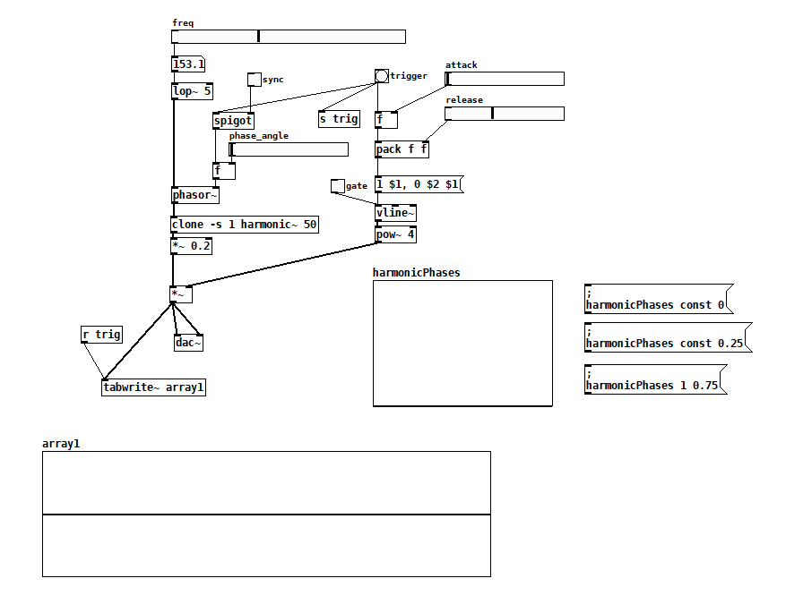
additiveSaw~.pd
harmonic~.pd
 posted in technical issues
FFT freeze help
Brace for wall of text:
My patch is still a little messy, and I think I'm still pretty naive about this frequency domain stuff. I'd like to get it cleaned up more (i.e. less incompetent and embarrassing) before sharing. I'm not actually doing the time stretch/freeze here since I was going for a real time effect (albeit with latency), but I think what I did includes everything from Paulstretch that differs from the previously described phase vocoder stuff.
I actually got there from a slightly different angle: I was looking at decorrelation and reverberation after reading some stuff by Gary S. Kendall and David Griesinger. Basically, you can improve the spatial impression and apparent source width of a signal if you spread it over a ~50 ms window (the integration time of the ear). You can convolve it with some sort of FIR filter that has allpass frequency response and random phase response, something like a short burst of white noise. With several of these, you can get multiple decorrelated channels from a single source; it's sort of an ideal mono-to-surround effect. There are some finer points here, too. You'd typically want low frequencies to stay more correlated since the wavelengths are longer. This also gives a very natural sounding bass boost when multiple channels are mixed.
Of course you can do this in the frequency domain if you just add some offset signal to the phase. The resulting output signal is smeared in time over the duration of the FFT frame, and enveloped by the window function. Conveniently, 50 ms corresponds to a frame size of 2048 at 44.1 kHz. The advantage of the frequency domain approach here is that the phase offset can be arbitrarily varied over time. You can get a time variant phase offset signal with a delay/wrap and some small amount of added noise: not "running phase" as in the phase vocoder but "running phase offset". It's also sensible here to scale the amount of added noise with frequency.
Say that you add a maximum amount of noise to the running phase offset- now the delay/wrap part is irrelevant and the phase is completely randomized for each frame. This is what Paulstretch does (though it just throws out the original phase data and replaces it with noise). This completely destroys the sub-bin frequency resolution, so small FFT sizes will sound "whispery". You need a quite large FFT of 2^16 or 2^17 for adequate "brute force" frequency resolution.
You can add some feedback here for a reverberation effect. You'll want to fully randomize everything here, and apply some filtering to the feedback path. The frequency resolution corresponds to the reverb's modal density, so again it's advantageous to use quite large FFTs. Nonlinearities and pitch shift can be nice here as well, for non-linear decays and other interesting effects, but this is going into a different topic entirely.
With such large FFTs you will notice a quite long Hann window shaped "attack" (again 2^16 or 2^17 represents a "sweet spot" since the time domain smearing is way too long above that). I find the Hann window is best here since it's both constant voltage and constant power for an overlap factor of 4. So the output signal level shouldn't fluctuate, regardless of how much successive frames are correlated or decorrelated (I'm not really 100% confident of my assessment here...). But the long attack isn't exactly natural sounding. I've been looking for an asymmetric window shape that has a shorter attack and more natural sounding "envelope", while maintaining the constant power/voltage constraint (with overlap factors of 8 or more). I've tried various types of flattened windows (these do have a shorter attack), but I'd prefer to use something with at least a loose resemblance to an exponential decay. But I may be going off into the Twilight Zone here...
Anyway I have a theory that much of what people do to make a sound "larger", i.e. an ensemble of instruments in a concert hall, multitracking, chorus, reverb, etc. can be generalized as a time variant decorrelation effect. And if an idealized sort of effect can be made that's based on the way sound is actually perceived, maybe it's possible to make an algorithm that does this (or some variant) optimally.
 posted in technical issues
FFT freeze help
Yeah, the running phase is really important. Without it, the [rifft~] will keep resetting the phase at the same value, when really it should be adding the incoming phase-difference to the previous output phase for continuity. This is how phase vocoder is able to faithfully synthesize the original frequencies, despite the fact that it has a finite resolution. Each bin is essentially a bandpass filter, and any frequency that gets through the filter is analyzed for magnitude and phase. But, if you can assume that only one frequency made it through the filter, the difference between the current frame's phase and the previous one will tell you the exact frequency, because only one frequency can advance its phase in that amount of time at that specific interval. So when you modify and resynthesize, you need to take that phase difference and accumulate it so the "oscillators" can continuously fine-tune themselves.
 posted in technical issues
Instantaneous beat slicer: source, binaries and GUI module
I will share soundtouch~ for Pd as a separate project, so far this works for Windows, OSX and Linux 32 bit but not for Linux 64 bit for some reason, and I'd like to get that right before uploading.
Pitch shifting and time stretching is in a way comparable to shaping steel plate work for a car body - if it is done without expensive machines, the quality is pathetically poor. I tried frequency domain pitch shifting (the phase vocoder method) following Stephan Bernsee's description at
http://www.dspdimension.com/admin/pitch-shifting-using-the-ft/
The problem with this basic method is phase randomisation in the output signal. It sounds like it's been fed through comb filters. To repair this, demands phase reinitialisation at every transient. Too complicated for me! For voice processing, I like Soundtouch better. But for some cases phase randomisation may be less of a problem and then the phase vocoder method is an option because it does not produce (so much) amplitude modulation. I could say a lot more on this topic but that would be for a new thread.
And yes, everything in sliceplay~ could be done with Pd patches, albeit with less precision. That is also the reason why slicerec~ and sliceplay~ are separate objects. You can access the buffer which is filled by slicerec~ with your own methods if you want something that sliceplay~ can not do (for example scrubbing).
Katja
 posted in extra~
Formant vocoder algorithm
thank you for your replay
but, no they are not the same
The phase vocoder is similar to the channel vocoder.
However, instead of estimating the pitch, the phase vocoder estimates the phase derivative at the output of each filter.
By coding and transmitting the phase derivative, this vocoder destroys the phase information
whereas
The formant vocoder can be viewed as a type of channel vocoder that estimate the first three or four formants in a segment of speech.
It is this information plus the pitch period that is encoded and transmitted to the receiver.
 posted in technical issues
\[zerox~\]
If you plan on using [xerox~] to phase sync two oscillators, it probably won't cut it. Generally, you want those things to be sample accurate. [xerox~] will give you a click corresponding to zero crossings out its right outlet, but, as far as I know at least, Pd's oscillators can't really use that for phase syncing ([xerox~] is actually based on a Max object, yet strangely Max's oscillators can't use it either). It would require a conversion to message rate to reset the phase, which kills sample accuracy, not to mention the fact that the phase input of [phasor~] quantizes to block boundaries (default 64 samples in Pd), which also kills sample accuracy.
However, if you know the ratio between your two oscillators, phase syncing can be achieved using a master [phasor~] to run both oscillators. Use the master sync frequency to drive the [phasor~], then multiply the output of the [phasor~] by the ratio between the synced (slave) oscillator and the master one. In other words, it should be multiplied by:
slave frequency / master frequency
Then, you just [wrap~] the signal and viola, you have a new synced phasor signal to drive the slave oscillator. The attached patch should hopefully clarify.
posted in technical issues
Transdetect~ and transcomp~: transient shaping and detection
transcomp~ uses transdetect~ to shape the initial attack and release of a signal.
Requires IEM's FIR~, fexpr~ and dbtorms~ which are provided in PD-Extended.
To work properly the transdetect folder should be added to PD's path.
Start by opening help-transcomp~.pd
01 Implementation:
transdetect~ works by using two pairs of envelope followers. The first pair
subtracts an envelope follower with a slow attack from an accurate follower,
the result of which is a signal containing the initial attack. For the initial
release, the second pair subtracts an accurate envelope follower from one with
a slow release.
An envelope follower measures the mean square power of a signal over time
(see 3.audio.examples/H06.envelope.follower.pd for details on implementing an
envelope follower). To do this we must use a low pass filter at a very low
frequency. In order to achieve an accurate follower a linear phase FIR filter
was used (using IEM's FIR~ external). Unfortunately this introduces a phase
delay.
In order to facilitate the use of different envelope follower implementations,
transdetect~ requires a filter type as a creation argument implemented in
followernameTransDetectEF~.pd. 4 linear phase fir implementations are provided:
181, 251, 451 and 501 taps filters. The 501 taps filter provides the most
accurate filter but with a phase delay of 5.668 ms at 44.1kHz (raise the
sampling rate to lower the phase delay). They were all generating using
http://www.dsptutor.freeuk.com/FIRFilterDesign/FIRFiltDes102.html with a
cutoff frequency between 5 and 10 Hz.
A compromise between accuracy and phase delay might be achieved by using
minimum phase FIR filters. A 5th implementation using PD's native lop~ object
is also provided under the designation iir (FIR~ not required).
Along with different possible envelope follower implementation transdetect~
also requires an attack and hold type implemented in
attacknameTransDetectAttackShape~.pd and holdnameTransDetectHoldShape~.pd
respectively. These implementations dictate the kind of attack and release
curves used on the envelope followers (linear, slow[er|est] and fast[er|est]).
All implementations provided use fexpr~. A more efficient external could be
made to take fexpr~ place.
02 Use
In help-transcomp~.pd patch enable start and pay attention to the snap in the
hit. Disable the green toggle button to disable the compression make the snap
go away. Check out the tables on the left to see the results of the transient
compression.
transcomp~ is useful when used with recorded drums to maximize or minimize
its transient (to make it punchier or to make snare drums less clappy).
transcomp~ uses transdetect~. By itself transdetect~ can be used to synthesis
hits from a recording. For example, take a bass drum recording and use the
signals generated by transdetect~ to shape the frequency and envelope of a
synthesized kick drum.
Would love to have some feedback and some help in turning the linear phase filters into minimum phase filters.
 posted in abstract~
Bank of oscillators - most efficient method
> Obi - doesnt the timbre suffer if all the phases are equal (sounds a bit static)? I
> think in the expensive version they are all running at different phases which
> makes the result richer. Can wrap~ be used to offset the phases and still be
> cheaper than a bank of osc~ objects
Yes, but it depends on how the wave is used. "Suffer" might not be the best word. Some sounds thrive on phase synchrony.
Having free running (independent) oscillators or a common phase makes very little difference to a constant timbre, a drone/sustained note. The ear doesn't pick out any phase relationships, even if they change slowly within the sound.
But if you want a very percussive sound, like a struck string, to sound correct and reliably trigget on each hit, you need to sync the phases.
The method given above is equivalent to using [sinesum( messages with [tabosc~] or waveshaping - the component phases are governed entirely by the driving waveform. In a polyphonic instrument each voice would be identical and the total result would sound dry/sampled/2D. But with independent oscillators each voice would start with subtly different component phases, and the total result is much deeper/richer/fat.
To compromise efficiency and quality it's good to supplement very terse methods like the one shown with some chorus/flanger/phaser
About [wrap~], it is unneccesary in this case because [cos~] is a periodic function which already remaps the domain. In fact the domain offset _is_ the phase offset, but in out case they are all integers (multiples of 2 * pi if we didn't have Pd rotation normalised functions) so each is a harmonic that aligns with one beneath it. [wrap~] could be used to align phases from a line. In fact a [line~] plus a [wrap~] is a [phasor~]. But we wouldn't get different frequencies by taking the cosine of shifted copies, instead we need to multiply each new phase by a constant to change its slope. The slope multiplier, m in the equation y = mx+c, gives the rate of change and hence the frequency. Interestingly that means if the phases are synced perfectly there's always a transient at the start t=0 where every cosine must be simultaneously 1, so great for struck body sounds.
 posted in technical issues