Little help with pitshifter.
oh shoot! okay. I use a vline~ to feed tabread4~ so the method is a little different
The mtof part is designed to calculate a ratio - so if you input a zero into the left part, the result is one. If you input something like -5, it will give you a value that is less than one. You can multiply that value by the length of the sample in ms to get how long the sample would play back if you wanted it to play at 5 semitones above(?) the base pitch of the sample. You have to choose a midi note to start at. Above that note, the sample will play faster, below that note the sample will play slower. I think I calculate this value by taking the base note and subtracting from that the note from the midi keyboard.
You want to use the tabread4~ method from the (3.7.1.1.) example, but instead of feeding it with a phasor~, try feeding it with a vline~. Then you can calculate the length in samples of your sample. That's the left output of soundfiler. Dividing length in samples by the samplerate~ gives you the lenght of the sample in seconds. Multiply that by 1000 and you have the the length in milliseconds. vline~ takes input in milliseconds. Send it a message to ramp from 0 to the number of samples in your sample in the number of milliseconds you just calculated. If you want to repitch it, also multiply by the midi ratio from above.
If you want to use phasor~ instead, you're setting frequency in Hz. So instead of multiplying the sample length by 1000, you might want to multiply it by the ratio and then get the reciprocal of it with this:

Then feed that to the phasor~
Are you going to use phasor~ in your design? I could double check that there's not a better transposing method with phasor.
Actually, it might be way easier with phasor, You could convert your current input to phasor to midi with ftom, then add transposition in semitones and then convert back to a frequency...
 posted in abstract~
Tabread4~~ example (or alternative)
@Gabriel-Lecup If you just want to loop at normal speed then you can use [tabplay~]
It will be sample perfect.
You just have to deal with waveform mismatch at the loop point..... which will cause clicks.
If you want to change the playback speed then you have another problem.
Artefacts are unavoidable. Well I will qualify that. As you reduce the playback speed you have to increase the original sample-rate of the Sample compared to your output sample-rate to avoid them. Half speed... double the sample-rate of the Sample. You cannot do that in Pd as far as I know.
If you cut the playback speed in half. This causes everything to sound an octave lower because the time stretching makes all the soundwaves twice as long, which means their frequencies will be cut in half and thus sound an octave lower.
This leads the problem that every single sample you use needs to be played twice or else there will be gaps (a much worse "artefact"). To avoid this problem you can use [tabread4~], which interpolates intermediate values that it generates using information from the values that ultimately precede and follow it.
If you increase the playback speed then samples are dropped. This unavoidably creates artefacts as well. As you say, with a tone they will be audible.
Filters can help with high frequency ringing, but might already be built into the object.... though probably not, because you can see the ringing in [B04.tabread4.interpolation].pd in the doc folder.
Someone might know whether [tabread4~] (or [tabread4~~] even), uses quadratic or cubic interpolation. Checking the processing overhead might tell you....... https://www.maximalsound.com/mastering/interpolation methods.pdf
You need to add 2 samples to the array for [tabread4~] ((see [tabread4~-help])) to do it's math playing back the whole sample.
I had never thought about it, but 2 zero samples should probably be inserted after a loop point to allow the curve to interpolate to zero. This would also avoid any post Sample clicks. But how?
I assume that [tabread4~~] which seems not to be available to me on windows, uses double precision.
That will give more accuracy for bit depth, but the samples still arrive at the same speed, so I cannot see how it helps you here. 64-bit precision interpolation over 32-bit precision. Audible? I would be very surprised.
If it is working well for the patch that @beep.beep has kindly posted then I can only assume that [tabread4~~] deals automatically with the 2 sample overhang.
David.
 posted in technical issues
Build a MIDI controller with the Arduino, Firmata and Pure Data
Time to start contributing some knowledge back to the wonderful world that is the internet; today, a step by step nice and easy tutorial on getting started to building your own MIDI controllers with the arduino.
When researching for my ableton controller project, I didn’t find much out there about using firmata on an arduino to send data to software. The standard approach just seemed to be create the code in the arduino language, upload it to your board and hack one of those MIDI to USB cables as a bodge job way of getting the MIDI out of the arduino.
So why firmata and pure data? Well the whole idea of firmata is that you flash it to your arduino, and it throws out serial about whats going on with the arduino inputs and outputs, then you decide how the software treats the readings coming in and going out.
Theory out the way, lets build some controllers. You’ll need a few things…
HARDWARE:
An arduino and something to wire into it (for this i’ll be using a pot)
A USB cable for your arduino
SOFTWARE:
Arduino – http://arduino.cc/en/Main/Software
Pure Data – http://puredata.info/downloads
Firmata – http://at.or.at/hans/pd/objects.html#pduino
Something to patch your new controller into; like Reason or Ableton Live
- SETTING UP FIRMATA AND PURE DATA
Install Pure Data and create a folder to store all your patches somewhere. Unzip Firmata and add the files ‘arduino.pd’, ‘arduino-test.pd’ and ‘arduino-help.pd’ to your new Pure Data folder. The ‘arduino.pd’ file is the object that we use in PD for opening up communication with your arduino and routing it to PD. Done? Awesome, your software is almost set up.
- FLASHING FIRMATA TO YOUR ARDUINO
Install the latest version of arduino and open it up. Connect your arduino with the USB cable to your laptop (i’m using a macbook for this by the way). In the example patches, open up “Standard Firmata”, select your board (im using an arduino mega), and your serial port (look for tty.usbserial for use with a USB cable). Then compile and hit the upload button and your arduino is now ready to use firmata and communicate with Pure Data!
- WIRING UP A POT
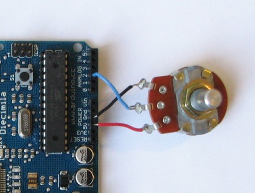
Potentiometers are cool, and theres a great arduino tutorial of how to wire one up here: http://www.arduino.cc/en/Tutorial/Potentiometer
Basically, all you need to know is that there are three pins; your two outer pins govern voltage flow across the pot, meaning one has to be 5V and the other has to be ground. It doesn’t matter which, but your 5v pin is going to be where your pot reads maximum, so convention dictates this should be the right hand pin. The center pin needs to be connected to an analog in on the arduino and will read the value of the pot as it sweeps from ground (0v) to 5v.
All wired up? Plug it into your laptop and open Pure Data, we’re ready to get things talking.
- SETTING UP OUR PATCH
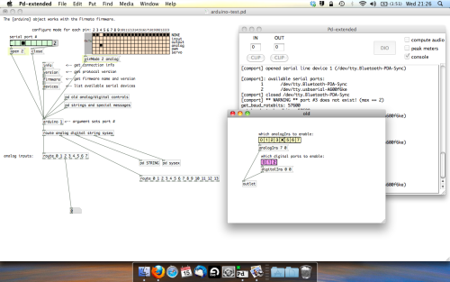
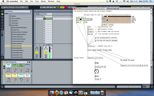
Open the example “arduino-test.pd” Pure Data patch you copied over earlier. It should look like this one…
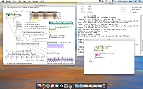
The test patch has everything we need to open a connection and enable pins. Firstly, lets delete a bunch of stuff and make our window a bit bigger. Hit Command + E to enter edit mode in Pure Data.
Ok a quick explaination; the key component here is the ‘arduino’ object. This is being drawn from the file you copied in earlier, and is what communicated with your arduino. Here we can do everything to control the arduino from opening a connection, to receiving data.
The large grid allows us to set the mode of each pin on the arduino. Remember pins 0 and 1 are reserved for Rx and Tx. I’m using analog pin 4 for this demo, so I’ve set my pin mode for pin 4 to ‘analog’.
Now we can plug our arduino in and get a reading from the potentiometer.
- ARDUINO INTO PURE DATA
With your arduino plugged in, hit command and E to bring us out of edit mode. In our patch, click on ‘Devices’ above the arduino object and open up the pure data terminal. (That other thing that loads with PD that has all the scary code in)
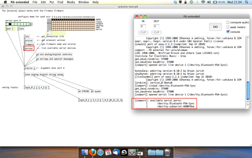
The “Devices” message connected to the arduino object pings your computer to find what devices are connected and on what serial ports. Since we’re using a USB cable to connect our arduino, we’re looking for something with ‘usbserial’ in it, in this case; port 2.
Select the relevent port in the green box at the top (remember the first box is ‘0’, second is ‘1’ and so forth) and hit ‘Open’ to establish a connection. Check the terminal to see if the connection was sucessful.

Now lets check we’re getting something in. Create a number box (Command + 3) and connect it to the relevent pin on the ‘Route analog’ box at the bottom. In this case, pin 4.
One more thing; if you’re not getting any readings in, you’ll need to click on ‘pd old analog/digital controls’ and enable your pins here too. What I tend to do in my patches is just not include the large grid but make my own ‘old pd’ controls custom to what i’m enabling/disabling to save space.
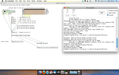
Here’s what the ‘old analog/digital controls’ subpatch looks like (pin 4 enabled)…
Come out of edit mode and check that you’ve got readings. If so congratulations! If not, troubleshoot, start with making sure your usb connection is opened, make sure all the correct pins are enabled (remember you’re counting from 0 not 1 on most of these buttons in PD, it’s just the way computers work).
- SCALING READINGS TO MIDI
So we’ve got a reading and chances are it’s to 3 decimal places between 0 to 1. No problem, create a new object (Command + 1) and type “autoscale 0 127”. This allows us to scale the input to a min and max value, in this case 0 to 127 of MIDI. Next, lets get things looking nice, create a new object and type “knob”. Connect this AFTER the autoscale object. (the knob is default set to read inputs from 0 to 127. Then create another number to display the scaled MIDI data coming out, and finally a new object and type “ctlout 1”.
It should look something like this…
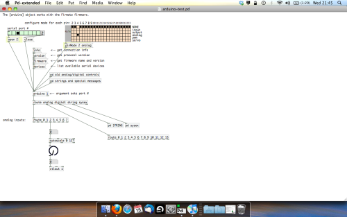
The second box should be outputing values from 0 – 127 now, and the knob giving a visual representation of your potentiometer.
Now lets patch it into ableton…
- PURE DATA TO ABLETON LIVE
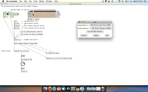
Firstly, you’ll need to set up your macs IAC driver if you’ve not done this. Basically you’ll need to go into Audio/MIDI preferences and enable your IAC driver. Then create a new input and output. One for input to DAW and one for output from DAW. Google around for a tutorial on this, its really simple, a 30 second job.
After you’ve set up your IAC driver, go back to PD and go to preferences > MIDI Settings, and connect your IAC driver.
Open ableton and go to its MIDI preferences. Create a device listing for your IAC driver and enable its ins and outs into ableton like so…
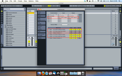
And thats it! Create an instrument and try to assign something! I’ve got it controlling the brightness of a bass sound here.
Shout out for Facu who requested this tutorial. Hopefully it’ll help some of you looking to get into this stuff and start building things but with no idea where to start.
 posted in tutorials
sampling rate impacting sound
Not entirely sure about the math of the whole thing, but what I know is that when you use Jack as your audio server, you don't change your audio setting in Pd, but only in Jack.
Check this, start Jack (in the image you posted, the sampling rate is at 48KHz), then start Pd and open its audio settings. Most likely it will read a 44.1KHz sampling rate. Don't change that, open a new patch and put a [samplerate~] connected to a [print]. Bang it and see what it prints. It should print 48000 and NOT 44100. This is because Jack's sampling rate is at 48000 and that's the sampling rate Pd is using, even though its settings read 44100.
What happens, I guess, is that when you change Pd's audio settings you force a different sampling rate between the client (Pd) and the server (Jack), which causes this frequency difference, which probably occurs due to two different samplings of the same frequency.
The only thing you should probably set in Pd's audio settings (if I'm not mistaken), is the number of channels of your sound card.
 posted in technical issues
Multiple patches sending to the same Arduino / change block size?
I'm working on a project involving Pure Data and Arduino. The idea is to play an audio file while controlling a pump that breathes air into an aquarium, based on the envelope of the audio, so that the bubbles correspond to the voice that you hear in headphones.
My problem is, while it works perfectly with one aquarium (playing the audio file + controlling the pump), it's less precise, and sometimes completely off, when I'm adding the others.
Files : main.pd, aquarium.pd, arduino.pd
The logic of one aquarium is inside an abstraction, [aquarium], with the file, threshold, audio output and Arduino pin as creation arguments. Every instance of the abstraction is playing its own file into a given audio output, and sending messages to the Arduino ("turn on pump X" or "turn off pump X"). It works quite well for most of the aquariums, so I guess (hope) the fix must be simple.
I tried different ideas to limit the message flow but didn't quite succeed (hence the mess below the [dac~] object, this stuff is not used anymore).
I only recently thought about increasing block size, thinking that would reduce the number of messages sent to the Arduino. However using the audio settings, it didn't seem to change anything, and I'm not sure how to use the [block~] object. Do I have to send the audio output through an [outlet~] object? I guess that would mean each of my 9 [aquarium…] blocks would need to have 9 outlets going into a [dac~] object in my main patch, and that would be a big spaghetti plate ")
I'd be curious to know if any of you has ever encountered this kind of issue, or has an idea to fix it, either with block size, pure data magic or anything else…
Thanks!
 posted in technical issues
Pure Data / Raspberry Pi / Realtime Audio / Permissions
THE GOAL:
I want my Raspberry Pi 2 to automatically start up the Jack server with realtime scheduling, and subsequently start Pure Data with realtime scheduling, load a patch &c. without any user intervention from a login shell.
As a performance artist working primarily with psychodrama (the technology is definitely NOT the important part here), fiddling around at a terminal right before or during a performance is kind of... psychically inconvenient. I need a box that I can plug in, give the audio output to the sound guy, and be ready to go.
PREREQUISITES:
I use Raspbian with a Linux kernel compiled with realtime goodness. I have hand-compiled Jack2 and Pure Data with realtime support in order to take advantage of this. Running a process with realtime priority requires the proper PAM directives set in /etc/security/limits.conf and related places, but that is beyond the scope of this little write-up.
Also somewhat relevant: I use a M-Audio MobilePre USB soundcard (sounds pretty awful by today's standards, but it's an extremely USEFUL box and sounds good enough for the work I do). For full-duplex sound, this requires the RasPi's USB to be set to single speed. In this configuration, I can get just under 2.9ms latency with good CPU overhead for Pure Data to run a few of my 64-voice wavetable and delay line granulators. Yeah!
THE PROBLEM:
Purely by happenstance, I had given the jackd command in my startup script the option “-s” which allows the server to ignore overruns and so on. So things seemed to be working as expected, but I noticed a lot more glitches than when I manually started up Jack and Pd from the terminal without the “-s” option. Upon removing it from my startup script, everything failed! WAH.
So I started piping STDERR and STDOUT to text files so I could read what either Jack or Pd were complaining about. As it turns out, Jack was unable to start with realtime priority due to a permissions problem. (I assume this is one of the things the “-s” options allows jackd to ignore, and thus start up with non-realtime priority. Problem is that Pure Data can’t connect to a non-realtime Jack server when its “-rt” option specified.)
Now, I had already been through the whole rigamarole of setting proper memory and priority limits for the “audio” group, to which the user “pi” belongs. So I thought, okay, I have to execute these commands as “pi”, and while simulating a login shell because the security limits in question are only set during login.
So I did this:
su -l pi -c "/usr/local/bin/jackd -R -dalsa -dhw:1,0 -p128 -n3 -r44100 -S >> /home/pi/jackd.log 2>&1 &"
This says “login as user ‘pi’ and then run the jackd command with these options, piping the outputs to this log file and run it in the background”. Well, I still got all the same errors about not being able to set realtime priority. WHYYYYYYYYY?
THE SOLUTION:
I hunted and hunted and hunted on a Very Popular Search Engine til I decided to try searching “security limits not loaded with su -l” and found this.
(Makes me think of that Talking Heads lyric, “Isn’t it weird / Looks too obscure to me”.)
So by uncommenting the line # session required pam_limits.so in /etc/pam.d/su everything started working as expected.
CONCLUSION:
I now know a LOT MORE about PAM and how important it is to keep in mind when and in what order scripts and other little subsystems are executed; but also that sometimes the problem is EXTREMELY OBSCURE and is to be found in some seemingly far-flung config file.
I hope this helps anybody out there working with Pure Data and the RasPi. The second generation board really packs quite a punch and can run several hundred audio grains (run by vline~ and enveloped by vline~ and cos~) simultaneously without a problem. And I'm pretty sure this is just using ONE of the 4 cores!
I'm by no means an expert Linux sysadmin, so if you have any other suggestions or corrections, please let me know! I wouldn't have been able to get this far without all the generous and helpful writeups everybody else has contributed, both within the RasPi and Pure Data communities. If you have any questions about anything I glossed over here, I'll do my best to answer them.
 posted in tutorials
0mms delay time in pd is it a dream?
0ms will be impossible I suspect just due to the way that digital audio works.
Start by assuming that everything is dealing with 64 sample blocks of audio. This is a big assumption as I'm not sure how audio hardware is going to do what it does but it should be fine for some rough calculations.
We'll also just be dealing with one channel here.
Audio hardware needs to capture that 64 samples of data from one channel. It won't send that data down the USB/Firewire/PCI bus until it has the full 64 samples which means that there is already delay there, the first sample won't be sent until the last is captured.
(1 second / 44100 samples) * 64 = 0.00145 or about 1 and a half milliseconds
Even with the best audio hardware this limitation is still there.
On top of this you need to add on the time to process the audio, there will probably be some time wasted scheduling everything etc etc. ultimately you're always going to have a couple of milliseconds latency between audio coming into the computer and then going back out.
that said, how much of an issue would 5ms latency be? generally people can't notice anything less than 20ms of latency and I understand that Yamaha engineers aim for about 4 or 5 ms of latency with all their electronic midi controllers/instruments as that's the point that it sounds instantaneous to people.
Someone with more experience here please feel free to correct me if I'm wrong though
 posted in technical issues
Phasor~ as index to tabread~ with del and line~ envelope glitch
Hey
I'm using phasor for an index to a tabread~ to play a sample.
I'm also using line~ as an envelope to control audio output.
The timing for the envelope is set by the size of the sample size and samplerate~ as well as the frequency for the phasor~.
The magnitude of the phasor is adjusted to the sample size.
The sample player can be re-triggered and when this happens a line~ is set to go to 0 in 5ms,
a delay is set for 5ms,
then bangs another line~ to go to velocity in 0,
as well as setting phasor~ frequency to 1/t and phase to zero.
At which time another delay is setup at samplelength in ms.
After the sample is played the phasor~ frequency is set to 0 then
another line~ to 0 in 5ms is sent to the [*~] .
This causes a glitch when the sample is retriggered because the phasor~ is reset to zero and starts replaying the sample.
This glitch can not be heard when the sample is not re-triggered so maybe it's a control vs signal timing issue.
I did hear the glitch at the end of the sample re-triggered or not using vline~.
So my question is how do you do audio rate envelope triggering of envelopes ? I would post the patch but it is a mess. A good answer or pointer to some reference material would be greatly appreciated. I haven't quite wrapped my head around the sample and hold sampler examples yet.
 posted in technical issues
Audio glitch with portaudio in PD
Hi everyone,
I'm having an issue with audio output in PD : when setting audio to output via portaudio, all the audio that gets out of PD has audio glitch in it, some kind of random-spaced crackles or clicks. It is completly useless as such. Increasing the delay in PD's audio settings doesn't change a thing.
However, using Jack as an audio outlet supresses all this problem, and the audio is clean that way.
Would anyone know the reason for this? I would be glad to know it as there may be a link with another issue about audio on my hardware : system audio of mac os X has the same kind of glitches that I got with PD on portaudio, only it's only occasional glitches so it's bearable. Solving this issue would be a big relief to me.
My hardware is a hackintosh (pc with osX installed on it), and mbox2 as audio interface (but I have tested with an m-audio transit and I have the same crackling issue). My soft is osX Snow Leopard 10.6.5.
Any help appreciated!
 posted in technical issues
Arduino, ultrasonics and Pd: HELP needed for degree project!
Dear Pd'ers… I'm fairly new to Pd and have been using it during my 'Audio Production' degree at SAE college in London. I'm here to ask for help on my final degree project, which aims to control objects within Pd by way of proximity sensors connected to Arduino.
I have had moderate success, first using a Sharp GPD12 IR sensor connected to an analog port on an Arduino Diecimila, then a Devantech SRF02 connected via I2C to Arduino. I have managed to get Pure Data reading the sensor values using the Pure Data example included in SimpleMessageSystem (http://www.arduino.cc/playground/uploads/Code/SimpleMessageSystem.zip)... and only altering the number of the comport the Arduino appears on.
On the Arduino end, I have added the SimpleMessageSystem library, and am using the following sketch to run one or both of the sensors depending on whether or not I omit the SRF02 or GPD12 parts of the code.
// top //
#include <Wire.h>
#include <Servo.h>
#include <SimpleMessageSystem.h>
int sensorPin = 0;
int sensorValue = 0;
Servo servo1;
#define sensorAddress 0x70
#define readInches 0x50
#define readCentimeters 0x51
#define readMicroseconds 0x52
#define resultRegister 0x02
void setup()
{
Wire.begin();
Serial.begin(9600);
}
void sendCommand (int address, int command) {
Wire.beginTransmission(address);
Wire.send(0x00);
Wire.send(command);
Wire.endTransmission();
}
void setRegister(int address, int thisRegister) {
Wire.beginTransmission(address);
Wire.send(thisRegister);
Wire.endTransmission();
}
int readData(int address, int numBytes) {
int result = 0;
Wire.requestFrom(address, numBytes);
while (Wire.available() < 2 );{
}
result = Wire.receive() * 256;
result = result + Wire.receive();
return result;
}
void loop()
{
// SRF02 READING //
sendCommand(sensorAddress, readInches);
delay(70);
setRegister(sensorAddress, resultRegister);
int sensorReading = readData(sensorAddress, 2);
Serial.println(sensorReading);
delay (200);
// GPD12 READING //
sensorValue = analogRead(sensorPin);
int range = (6787 / sensorValue);
Serial.println(range);
delay(200);
}
// bottom //
Pure data is picking up the sensor's output as a decimal number, through the serial port, correctly, and showing this as a number in the SPECIAL CHARACTER section of the Pd patch, which I can then use to control various Pd parameters, like a slider for example.
If printing both sensor readings to the serial, the Pd patch will pick up the two sensor values alternately, but there seems no way of differentiating the two sensors within Pd, as they both come through the serial. I have tried prepending the serial print at the Arduino stage with a tag such as "IR" or "UL" for each sensor, but this simply ends up in nothing coming through in Pd.
Using one sensor gives the ability to control parameters with a fairly narrow detection range, but for the final version I would like to incorporate 4 or 5 sensors in order that I can cover nearly a full 360 degree range.
After a bit of research I have gone and bought 4 x Maxsonar EZ0's. They've got a wider range than the Devantech sensors, and can operate via I2C, serial or PWM. A number of people online seem to mention the improved stability when operating via PWM, so I thought this could be kinda useful.
I am going to London Hackspace tomorrow to get help with wiring up the sensors to my Arduino Diecimila, but for now, my main problem seems to be how to achieve greater communication between Pure Data and the sensors. It's all very good and well being able to take the decimal readout from an analog input to give one set of values in Pd, but I would like to know how to either to read (and trigger) each sensor discretely via PWM, or to somehow differentiate between each sensor's analog output, so that I can have the different sensors controlling different objects within Pd.
As well as SimpleMessageSystem, I looked at using the Pduino object. But to be honest, it is either not working properly (I have noticed reported issues with bugginess), or I am being stupid, as it has totally boggled my brain. In theory though, it seems like it should be able to do what I want, ie. send and receive commands between Arduino and Pd.
****************************************
So…. my questions for anyone out there with a knowledge of using Arduino + multiple sensors (preferably Maxsonar EZ's) with Pd are:
What is most appropriate for my project?
- Simple Message System or Pduino?
- analog or PWM?
And how do I get proper communication between the two platforms so I can discern discrete values from each sensor?
I'd really like to get a discussion going with this as (a) it would really help me in my degree (which ends in about 4 weeks!!!) and (b) I really want to share what I am doing, especially as the discussions on Arduino/Pd communication on the various forums seem a little patchy (at least for noobs like me). I also hope to continue my research in the future, sharing any findings I make with the community…
****************************************
PS. In the sharing spirit, please check out the Radio Tuner patch I've just posted over on the patch section of this forum - it's my first successful attempt at Pd... I hope you enjoy
 posted in I/O hardware diy